EP0751045A2 - Système d'alimentation électrique pour un véhicule avec moteur à combustion interne - Google Patents
Système d'alimentation électrique pour un véhicule avec moteur à combustion interne Download PDFInfo
- Publication number
- EP0751045A2 EP0751045A2 EP96107325A EP96107325A EP0751045A2 EP 0751045 A2 EP0751045 A2 EP 0751045A2 EP 96107325 A EP96107325 A EP 96107325A EP 96107325 A EP96107325 A EP 96107325A EP 0751045 A2 EP0751045 A2 EP 0751045A2
- Authority
- EP
- European Patent Office
- Prior art keywords
- combustion engine
- internal combustion
- fuel
- fuel cell
- hydrogen
- Prior art date
- Legal status (The legal status is an assumption and is not a legal conclusion. Google has not performed a legal analysis and makes no representation as to the accuracy of the status listed.)
- Granted
Links
Images
Classifications
-
- H—ELECTRICITY
- H02—GENERATION; CONVERSION OR DISTRIBUTION OF ELECTRIC POWER
- H02J—ELECTRIC POWER NETWORKS; CIRCUIT ARRANGEMENTS OR SYSTEMS FOR SUPPLYING OR DISTRIBUTING ELECTRIC POWER; SYSTEMS FOR STORING ELECTRIC ENERGY
- H02J1/00—Circuit arrangements for DC mains or DC distribution networks
-
- B—PERFORMING OPERATIONS; TRANSPORTING
- B60—VEHICLES IN GENERAL
- B60R—VEHICLES, VEHICLE FITTINGS, OR VEHICLE PARTS, NOT OTHERWISE PROVIDED FOR
- B60R16/00—Electric or fluid circuits specially adapted for vehicles and not otherwise provided for; Arrangement of elements of electric or fluid circuits specially adapted for vehicles and not otherwise provided for
- B60R16/02—Electric or fluid circuits specially adapted for vehicles and not otherwise provided for; Arrangement of elements of electric or fluid circuits specially adapted for vehicles and not otherwise provided for electric constitutive elements
- B60R16/03—Electric or fluid circuits specially adapted for vehicles and not otherwise provided for; Arrangement of elements of electric or fluid circuits specially adapted for vehicles and not otherwise provided for electric constitutive elements for supply of electrical power to vehicle subsystems or for
-
- H—ELECTRICITY
- H02—GENERATION; CONVERSION OR DISTRIBUTION OF ELECTRIC POWER
- H02J—ELECTRIC POWER NETWORKS; CIRCUIT ARRANGEMENTS OR SYSTEMS FOR SUPPLYING OR DISTRIBUTING ELECTRIC POWER; SYSTEMS FOR STORING ELECTRIC ENERGY
- H02J2101/00—Supply or distribution of decentralised, dispersed or local electric power generation
- H02J2101/20—Dispersed power generation using renewable energy sources
- H02J2101/30—Fuel cells
-
- H—ELECTRICITY
- H02—GENERATION; CONVERSION OR DISTRIBUTION OF ELECTRIC POWER
- H02J—ELECTRIC POWER NETWORKS; CIRCUIT ARRANGEMENTS OR SYSTEMS FOR SUPPLYING OR DISTRIBUTING ELECTRIC POWER; SYSTEMS FOR STORING ELECTRIC ENERGY
- H02J2105/00—Networks for supplying or distributing electric power characterised by their spatial reach or by the load
- H02J2105/30—Networks for supplying or distributing electric power characterised by their spatial reach or by the load the load networks being external to vehicles, i.e. exchanging power with vehicles
- H02J2105/33—Networks for supplying or distributing electric power characterised by their spatial reach or by the load the load networks being external to vehicles, i.e. exchanging power with vehicles exchanging power with road vehicles
Definitions
- the invention relates to a power generation system for a vehicle with an internal combustion engine according to claim 1, and a method for operating such a system.
- an alternator for generating electrical energy, which is driven by the internal combustion engine.
- the electricity supplied by the alternator is made available to the electrical consumers in the vehicle.
- the alternator is also used to charge the vehicle battery.
- the invention has for its object to provide a power generation system for a vehicle with an internal combustion engine, through which the current can be made available to the electrical consumers with reduced fuel consumption and regardless of the current speed of the internal combustion engine. It is also an object of the invention to provide a method for operating such a system.
- the use of a fuel cell system instead of an alternator in a vehicle with an internal combustion engine has the advantage that the electricity required can be provided with significantly reduced fuel consumption due to the better efficiency of the fuel cell.
- the power of the fuel cell can be set independently of the speed of the internal combustion engine, so that the current generated electrical power can be adapted to the respective need.
- auxiliary units such as fans or air conditioning compressors
- a fuel cell offers the possibility of providing electrical current even when the internal combustion engine is switched off, so that improvements, for example in the air conditioning of the vehicle, are made possible.
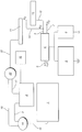
- the vehicle is driven with the aid of an internal combustion engine 1.
- a fuel tank 2 and a fuel line 3 are provided to supply the internal combustion engine 1 with liquid fuel.
- a fuel cell 4 is also arranged in the vehicle for generating electrical energy.
- An H 2 / O 2 fuel cell with a proton-conducting membrane, hereinafter referred to as a PEM cell, can preferably be used for this.
- PEM cell proton-conducting membrane
- the PEM cell 4 is supplied with oxygen via a first supply line 7 and hydrogen gas via a second supply line 8.
- the hydrogen is oxidized at the anode and the oxygen at the cathode is reduced.
- This electrochemical reaction creates a voltage between the two electrodes.
- many such cells can be combined into a so-called stack by connecting them in parallel or in series.
- pure hydrogen and oxygen only residual oxygen and water are released from the PEM cell 4 via an outlet line 9.
- the oxygen is supplied to the PEM cell 4 in the form of atmospheric oxygen.
- the required hydrogen is preferably separated from the fuel used for the internal combustion engine 1.
- Conventional fuels such as diesel, normal gasoline or methanol, contain hydrocarbons, from which hydrogen can be separated in a relatively simple manner, for example with the aid of a cracking plant 10.
- the exact structure of such splitting systems 10 is known in principle and is therefore not described further here.
- only a portion of the hydrogen is preferably separated from the fuel in the arrangement shown and the remaining fuel components subsequently recycled in internal combustion engine 1.
- the hydrogen is separated from the remaining fuel components in an H 2 separation system 11, the separated hydrogen being fed to the PEM cell 4 via a supply line 12.
- An H 2 intermediate store 13 can additionally be arranged in this supply line 12.
- This H 2 intermediate storage device 13 can be used, on the one hand, to supply the PEM cell 4 with hydrogen when the vehicle is started until the hydrogen supply via the gap system 10 is ready for operation.
- the hydrogen can then also be fed from the H 2 separation system 11 directly to the PEM cell 4 bypassing the H 2 intermediate storage 13 via a bypass line 14.
- Any device 11 known from the prior art can be used to separate the hydrogen from the remaining fuel components, for example based on metal foils.
- the fuel components remaining in the H 2 separation system 11 are discharged via a disposal line 15. There are several options for recycling these fuel components. Liquid components can be returned to the fuel tank 2 via a line 17. Gaseous constituents can be supplied to the internal combustion engine 1 via a line 18 either directly or preferably via a mixture generator 16, which is also connected to the fuel line 3. In this case, the mixture generator 16 is connected to the internal combustion engine 1 via a further line 19.
- An intermediate store 20 for the remaining fuel components can additionally be provided in the disposal line 15. This has the advantage that the remaining fuel components can be stored temporarily and can only be supplied to the internal combustion engine 1 when required. In the event that the PEM cell 4 is to be operated even when the internal combustion engine 1 is at a standstill, the use of such a buffer store 20 is particularly advantageous.
- the fuel components can then be fully or partially condensed in the intermediate store 20 and then fed to the fuel tank 2.
- the gaseous fuel components are then in turn fed to the internal combustion engine 1 via the mixture images 16.
- any other method can also be used to partially or completely separate hydrogen from the fuel, for example also by reforming the fuel.
- the current generated by the PEM cell 4 is supplied to the electrical consumers 5 in the vehicle.
- the electricity generated can be used to charge a battery 6, which is required to start the PEM cell 4 and / or the splitting system 10. An alternator is no longer used in this system.
- gaseous residues can be fed to the combustion engine 1 either directly or via the mixture pictures 16 for recycling.
- gaseous residues can also be buffered in the intermediate storage 20 and only supplied to the internal combustion engine 1 directly or again via the mixture images 16 with a time delay. It is also possible here to utilize the residues from the intermediate storage 20 only under predetermined operating conditions. If liquid constituents remain during the hydrogen separation, these can be fed to the fuel tank 2 as condensate. Care must be taken, however, that the fuel quality, in particular the ignitability, is not unduly impaired by the hydrogen separation.
- the PEM cell 4 can be operated as long as long as the internal combustion engine 1 is in operation and sufficient fuel is available. However, the operation of the PEM cell 4 is not restricted to the operating times of the internal combustion engine 1, as is the case with an alternator. Rather, it is also possible with this system to continue to generate electrical energy when the internal combustion engine 1 is at a standstill. Various concepts are possible for this. In the event of a brief interruption - in the range of a few minutes - hydrogen can be generated in the splitting system 10 until the intermediate store 20 is filled with the remaining fuel components. In the event of medium interruptions - in the range from 0.5 to 1.5 hours - the splitting system 10 can be switched off and the PEM cell 4 can be supplied with hydrogen from the H 2 intermediate store 13.
- the addition of suitable additives with low-boiling components into the fuel tank 2 can be provided to refresh the cleavability.
- the splitting system 10 can then be carried out relatively simply.
- the PEM cell 4 can be briefly supplied with hydrogen from the H 2 intermediate storage 13. Only after a predetermined operating time of the PEM cell 4 is the splitting system 10 started.
- the electrical energy for starting the PEM cell 4 and / or the gap system 10 is preferably provided by a battery 6. In such a system, the battery 6 can possibly be dimensioned correspondingly smaller in comparison to conventional vehicle batteries.
- the PEM cell 4 does not have to be operated with a constant load, but can be set as a function of the required current.
- a Control device which specifies the target power of the PEM cell 4 as a function of the number and the need of the connected electrical consumers 5.
Landscapes
- Engineering & Computer Science (AREA)
- Power Engineering (AREA)
- Fuel Cell (AREA)
- Output Control And Ontrol Of Special Type Engine (AREA)
- Electric Propulsion And Braking For Vehicles (AREA)
- Hybrid Electric Vehicles (AREA)
Applications Claiming Priority (2)
| Application Number | Priority Date | Filing Date | Title |
|---|---|---|---|
| DE19523109A DE19523109C2 (de) | 1995-06-26 | 1995-06-26 | Kraftfahrzeug mit Brennkraftmaschine und einem Stromerzeugungssystem |
| DE19523109 | 1995-06-26 |
Publications (3)
| Publication Number | Publication Date |
|---|---|
| EP0751045A2 true EP0751045A2 (fr) | 1997-01-02 |
| EP0751045A3 EP0751045A3 (fr) | 2000-03-22 |
| EP0751045B1 EP0751045B1 (fr) | 2003-12-10 |
Family
ID=7765242
Family Applications (1)
| Application Number | Title | Priority Date | Filing Date |
|---|---|---|---|
| EP96107325A Expired - Lifetime EP0751045B1 (fr) | 1995-06-26 | 1996-05-09 | Système d'alimentation électrique pour un véhicule avec moteur à combustion interne |
Country Status (3)
| Country | Link |
|---|---|
| US (2) | US6346340B1 (fr) |
| EP (1) | EP0751045B1 (fr) |
| DE (2) | DE19523109C2 (fr) |
Cited By (18)
| Publication number | Priority date | Publication date | Assignee | Title |
|---|---|---|---|---|
| EP1057997A1 (fr) * | 1999-05-29 | 2000-12-06 | Bayerische Motoren Werke Aktiengesellschaft | Moteur à combustion interne avec une pile à combustible comme source de tension/courant |
| WO2000076810A1 (fr) * | 1999-06-10 | 2000-12-21 | Siemens Aktiengesellschaft | Systeme d'alimentation en energie pour systemes impliques dans la securite montes dans un vehicule automobile |
| WO2001033653A1 (fr) * | 1999-10-29 | 2001-05-10 | Daimlerchrysler Rail Systems Gmbh | Dispositif pour l'alimentation electrique d'unites auxiliaires de vehicules sur rails |
| KR20010075224A (ko) * | 1998-09-30 | 2001-08-09 | 가나이 쓰도무 | 연료전지시스템 및 그것을 사용한 차량 |
| WO2001071838A3 (fr) * | 2000-03-18 | 2002-05-30 | Proton Motor Fuel Cell Gmbh | Installation combinee pile a combustible et moteur a combustion interne et/ou bruleur |
| WO2002053418A1 (fr) * | 2000-12-29 | 2002-07-11 | Siemens Aktiengesellschaft | Systeme de refroidissement pour module de piles a combustible faisant partie d'un systeme d'alimentation embarque |
| FR2821118A1 (fr) * | 2001-02-19 | 2002-08-23 | Peugeot Citroen Automobiles Sa | Procede et dispositif de rechauffage et de maintien en temperature d'un pot catalytique d'une ligne d'echappement d'un vehicule automobile |
| WO2002049131A3 (fr) * | 2000-12-16 | 2002-11-28 | Bayerische Motoren Werke Ag | Systeme de piles a combustible dans un vehicule dote d'un moteur a combustion et procede permettant son fonctionnement |
| EP1069069A3 (fr) * | 1999-07-06 | 2003-01-22 | Bayerische Motoren Werke Aktiengesellschaft | Dispositif de génération d'hydrogène gazeux |
| FR2832857A1 (fr) * | 2001-11-24 | 2003-05-30 | Bosch Gmbh Robert | Installation a pile a combustible |
| US6672415B1 (en) | 1999-05-26 | 2004-01-06 | Toyota Jidosha Kabushiki Kaisha | Moving object with fuel cells incorporated therein and method of controlling the same |
| EP1211743A3 (fr) * | 2000-12-04 | 2004-02-25 | Nissan Motor Co., Ltd. | Unité de production d'énergie à pile à combustible avec dispositif de reformage |
| US7041272B2 (en) * | 2000-10-27 | 2006-05-09 | Questair Technologies Inc. | Systems and processes for providing hydrogen to fuel cells |
| US7189280B2 (en) | 2004-06-29 | 2007-03-13 | Questair Technologies Inc. | Adsorptive separation of gas streams |
| EP1873859A1 (fr) * | 2000-06-08 | 2008-01-02 | Toyota Jidosha Kabushiki Kaisha | Système de pile à combustible pour piles à combustible |
| EP2348254A1 (fr) * | 2010-01-22 | 2011-07-27 | RV Lizenz AG | Dispositif d'entraînement sans émission |
| FR2999342A1 (fr) * | 2012-12-10 | 2014-06-13 | Snecma | Systeme de production d'electricite embarque avec pile a combustible |
| US10072841B2 (en) | 2010-01-22 | 2018-09-11 | Rv Lizenz Ag | Emission-free devices and method for performing mechanical work and for generating electrical and thermal energy |
Families Citing this family (45)
| Publication number | Priority date | Publication date | Assignee | Title |
|---|---|---|---|---|
| DE19703171A1 (de) * | 1997-01-29 | 1998-08-06 | Bayerische Motoren Werke Ag | Fahrzeug mit einem Antriebs-Verbrennungsmotor |
| US6921597B2 (en) * | 1998-09-14 | 2005-07-26 | Questair Technologies Inc. | Electrical current generation system |
| DE19902051C2 (de) * | 1999-01-20 | 2001-07-19 | Daimler Chrysler Ag | Stromversorgungssystem für ein Fahrzeug |
| DE19913795C1 (de) * | 1999-03-26 | 2000-10-05 | Daimler Chrysler Ag | Vorrichtung mit einer Brennkraftmaschine und mit einem Brennstoffzellensystem |
| DE19921816C1 (de) * | 1999-05-11 | 2000-10-26 | Andre Peine | Brennstoffzellen-System und Brennstoffzelle für derartiges System |
| DE19923738C2 (de) | 1999-05-22 | 2001-08-09 | Daimler Chrysler Ag | Brennstoffzellensystem und Verfahren zum Betreiben eines Brennstoffzellensystems |
| DE19924777A1 (de) * | 1999-05-29 | 2000-11-30 | Bayerische Motoren Werke Ag | Verfahren zur Erzeugung eines Hilfsbrennstoffes aus dem Betriebskraftstoff einer gemischverdichtenden Brennkraftmaschine, insbesondere auf Kraftfahrzeugen |
| DE19928102B4 (de) | 1999-06-19 | 2005-06-02 | Daimlerchrysler Ag | Fahrzeug mit einem Antriebs-Verbrennungsmotor und mit einem Brennstoffzellensystem zur Stromversorgung elektrischer Verbraucher des Fahrzeugs und Verfahren zum Betrieb eines derartigen Fahrzeugs |
| DE19932781C2 (de) | 1999-07-14 | 2003-07-24 | Daimler Chrysler Ag | Verfahren und Schaltungsanordnung zur Versorgung eines Bordnetzes eines Kraftfahrzeugs mit elektrischer Energie |
| JP3915334B2 (ja) | 1999-08-30 | 2007-05-16 | 株式会社豊田自動織機 | 燃料電池用水素供給システム、燃料リサイクル方法、液体運搬用移動体、給油設備及び燃料リサイクルシステム |
| US6627340B1 (en) * | 1999-11-06 | 2003-09-30 | Energy Conversion Devices, Inc. | Fuel cell hydrogen supply systems using secondary fuel to release stored hydrogen |
| DE10013477A1 (de) * | 2000-03-18 | 2001-10-18 | Volkswagen Ag | Brennstoffzellenvorrichtung und Verfahren zu dessen Betriebsdynamikverbesserung |
| AU2001264687A1 (en) * | 2000-05-19 | 2001-11-26 | Fortafil Fibers, Inc. | Method and apparatus for removing broken filaments |
| DE10028331C2 (de) * | 2000-06-05 | 2002-11-07 | Vodafone Ag | Brennstoffzellensystem und Verfahren zum Hochfahren eines Brennstoffzellensystems sowie Verwendung des Brennstoffzellensystems |
| DE10028329C2 (de) * | 2000-06-05 | 2003-06-26 | Atecs Mannesmann Ag | Brennstoffzellensystem und Verfahren zum Ein-/Abschalten eines Brennstoffzellensystems |
| DE10029886C1 (de) * | 2000-06-16 | 2001-10-31 | Kostal Leopold Gmbh & Co Kg | Kraftfahrzeug |
| DE10031061A1 (de) * | 2000-06-26 | 2002-01-17 | Siemens Ag | Vorrichtung zur Notabschaltung zumindest eines Standstromgerätes bei Fahrzeugen und Verfahren zum Abschalten zumindest eines Standstromgerätes |
| US7097925B2 (en) | 2000-10-30 | 2006-08-29 | Questair Technologies Inc. | High temperature fuel cell power plant |
| CA2325072A1 (fr) | 2000-10-30 | 2002-04-30 | Questair Technologies Inc. | Systeme de separation de gaz pour pile a combustible a carbonates fondus |
| DE10056429A1 (de) | 2000-11-14 | 2002-06-13 | Daimler Chrysler Ag | Brennstoffzellensystem und Verfahren zum Betreiben des Brennstoffzellensystems |
| DE10059949B4 (de) * | 2000-12-02 | 2005-12-15 | Conti Temic Microelectronic Gmbh | Verfahren zum Betreiben einer elektronischen Baugruppe für ein Kraftfahrzeug |
| DE10064251A1 (de) * | 2000-12-22 | 2002-07-04 | Volkswagen Ag | Brennstoffzellensystem mit Zwischenspeicher und Steuerungsverfahren |
| WO2002057105A1 (fr) * | 2001-01-17 | 2002-07-25 | Robert Bosch Gmbh | Dispositif d'entrainement, notamment pour un vehicule, comprenant un moteur a combustion interne et au moins un generateur de courant electrique |
| US6631943B2 (en) | 2001-01-26 | 2003-10-14 | Mueller Hermann-Frank | Sliding roof for motor vehicles |
| JP4393002B2 (ja) * | 2001-02-01 | 2010-01-06 | ヤンマー株式会社 | ガスエンジン |
| JP4713758B2 (ja) * | 2001-05-01 | 2011-06-29 | 本田技研工業株式会社 | 燃料電池発電システム及びその運転方法 |
| DE10132558A1 (de) * | 2001-07-09 | 2003-01-30 | Audi Ag | Kraftfahrzeug mit einem Verbrennungsmotor und einem Fahrzeugversorgungssystem zur elektrischen Energieversorgung mindestens eines elektrischen Verbrauchers |
| DE10148854B4 (de) * | 2001-10-04 | 2009-02-26 | Robert Bosch Gmbh | Kraft-Wärme-Anlage und Verfahren zur Erzeugung von elektrischer und thermischer Energie |
| JP2006505095A (ja) | 2002-03-14 | 2006-02-09 | クエストエアー テクノロジーズ インコーポレイテッド | 固体酸化物燃料電池用の水素リサイクル |
| CN100493670C (zh) | 2002-03-14 | 2009-06-03 | 探索空气技术公司 | 结合压力波动和置换净化进行气体分离的设备和系统 |
| DE20205813U1 (de) * | 2002-04-12 | 2003-02-20 | Hymer AG, 88339 Bad Waldsee | Freizeitfahrzeug mit Bordstromversorgung über Brennstoffzelle |
| US6682458B2 (en) * | 2002-06-19 | 2004-01-27 | Ford Motor Company | Method for operating a vehicle and a vehicle which incorporates the method |
| DE10227530A1 (de) * | 2002-06-20 | 2004-04-01 | Daimlerchrysler Ag | Kraftfahrzeug |
| US7285350B2 (en) | 2002-09-27 | 2007-10-23 | Questair Technologies Inc. | Enhanced solid oxide fuel cell systems |
| DE10300880A1 (de) * | 2003-01-13 | 2004-08-12 | Bayerische Motoren Werke Ag | Verfahren und System zur Bereitstellung elektrischer Energie in einem Straßenkraftfahrzeug |
| US20040197612A1 (en) * | 2003-02-26 | 2004-10-07 | Questair Technologies Inc. | Hydrogen recycle for high temperature fuel cells |
| JP4525008B2 (ja) | 2003-07-02 | 2010-08-18 | トヨタ自動車株式会社 | エネルギ出力装置およびエネルギ出力装置の制御方法 |
| DE102004005446A1 (de) * | 2004-02-04 | 2005-08-25 | Robert Bosch Gmbh | Mit Brennstoff betreibbare Vorrichtung zur Wandlung von Energie, insbesondere Brennstoffzellenvorrichtung |
| US7443803B2 (en) * | 2004-03-23 | 2008-10-28 | Fujitsu Limited | Estimating and managing network traffic |
| WO2006052937A2 (fr) | 2004-11-05 | 2006-05-18 | Questair Technologies, Inc. | Separation de dioxyde de carbone d'autres gaz |
| US7443083B2 (en) | 2005-04-27 | 2008-10-28 | Drexel University | Piezoelectric powered vehicles and motors |
| DE102006044138A1 (de) * | 2006-09-15 | 2008-03-27 | Siemens Ag | Energiespeichersystem für ein Kraftfahrzeug und Verfahren zum Steuern eines Energiespeichersystems |
| UY33038A (es) | 2009-11-20 | 2011-06-30 | Rv Lizenz Ag | Uso termico y quimico de sustancias cabonaceas en particular para la generacion de energia sin emisiones |
| DE102013214826A1 (de) * | 2013-07-30 | 2015-02-05 | Bayerische Motoren Werke Aktiengesellschaft | Fahrzeug mit thermoelektrischem Generator |
| JP6747062B2 (ja) * | 2016-05-31 | 2020-08-26 | 株式会社デンソー | 制御装置 |
Family Cites Families (10)
| Publication number | Priority date | Publication date | Assignee | Title |
|---|---|---|---|---|
| DE2417436A1 (de) * | 1974-04-10 | 1975-10-30 | Daimler Benz Ag | Einrichtung zur speisung des elektrischen bordnetzes von kraftfahrzeugen |
| US4489242A (en) | 1981-01-22 | 1984-12-18 | Worst Marc T | Stored power system for vehicle accessories |
| US4650729A (en) * | 1984-08-10 | 1987-03-17 | Nissan Motor Co., Ltd. | Electric power source device |
| DE3434532C1 (de) * | 1984-09-20 | 1986-02-13 | Messerschmitt-Bölkow-Blohm GmbH, 8012 Ottobrunn | Stromversorgungssystem für ein Kraftfahrzeug |
| US5284717A (en) * | 1989-12-27 | 1994-02-08 | Petroleum Energy Center | Method for producing raw materials for a reformer by cracking and desulfurizing petroleum fuels |
| JP3333877B2 (ja) * | 1990-11-23 | 2002-10-15 | ビーエイイー システムズ マリン リミテッド | 動力発生システムへの燃料電池の適用 |
| US5248566A (en) * | 1991-11-25 | 1993-09-28 | The United States Of America As Represented By The United States Department Of Energy | Fuel cell system for transportation applications |
| US5346778A (en) * | 1992-08-13 | 1994-09-13 | Energy Partners, Inc. | Electrochemical load management system for transportation applications |
| JPH06140065A (ja) * | 1992-09-08 | 1994-05-20 | Toshiba Corp | 燃料電池発電システム |
| US6077620A (en) * | 1997-11-26 | 2000-06-20 | General Motors Corporation | Fuel cell system with combustor-heated reformer |
-
1995
- 1995-06-26 DE DE19523109A patent/DE19523109C2/de not_active Expired - Lifetime
-
1996
- 1996-05-09 EP EP96107325A patent/EP0751045B1/fr not_active Expired - Lifetime
- 1996-05-09 DE DE59610856T patent/DE59610856D1/de not_active Expired - Fee Related
- 1996-06-26 US US08/672,065 patent/US6346340B1/en not_active Expired - Fee Related
-
2000
- 2000-01-13 US US09/482,055 patent/US6210822B1/en not_active Expired - Fee Related
Cited By (25)
| Publication number | Priority date | Publication date | Assignee | Title |
|---|---|---|---|---|
| KR20010075224A (ko) * | 1998-09-30 | 2001-08-09 | 가나이 쓰도무 | 연료전지시스템 및 그것을 사용한 차량 |
| US7273120B2 (en) | 1999-05-26 | 2007-09-25 | Toyota Jidosha Kabushiki Kaisha | Moving object with fuel cells incorporated therein and method of controlling the same |
| US6672415B1 (en) | 1999-05-26 | 2004-01-06 | Toyota Jidosha Kabushiki Kaisha | Moving object with fuel cells incorporated therein and method of controlling the same |
| EP1055545B1 (fr) * | 1999-05-26 | 2004-01-28 | Toyota Jidosha Kabushiki Kaisha | Véhicule hybride avec piles à combustible intégrées et sa méthode de contrôle |
| EP1057997A1 (fr) * | 1999-05-29 | 2000-12-06 | Bayerische Motoren Werke Aktiengesellschaft | Moteur à combustion interne avec une pile à combustible comme source de tension/courant |
| WO2000076810A1 (fr) * | 1999-06-10 | 2000-12-21 | Siemens Aktiengesellschaft | Systeme d'alimentation en energie pour systemes impliques dans la securite montes dans un vehicule automobile |
| EP1069069A3 (fr) * | 1999-07-06 | 2003-01-22 | Bayerische Motoren Werke Aktiengesellschaft | Dispositif de génération d'hydrogène gazeux |
| WO2001033653A1 (fr) * | 1999-10-29 | 2001-05-10 | Daimlerchrysler Rail Systems Gmbh | Dispositif pour l'alimentation electrique d'unites auxiliaires de vehicules sur rails |
| WO2001071838A3 (fr) * | 2000-03-18 | 2002-05-30 | Proton Motor Fuel Cell Gmbh | Installation combinee pile a combustible et moteur a combustion interne et/ou bruleur |
| USRE43219E1 (en) | 2000-06-08 | 2012-02-28 | Toyota Jidosha Kabushiki Kaisha | Fuel cell fuel supply system and mobile body |
| EP1873859A1 (fr) * | 2000-06-08 | 2008-01-02 | Toyota Jidosha Kabushiki Kaisha | Système de pile à combustible pour piles à combustible |
| US7674539B2 (en) | 2000-10-27 | 2010-03-09 | Xebec Adsorption Inc. | Systems and processes for providing hydrogen to fuel cells |
| US7041272B2 (en) * | 2000-10-27 | 2006-05-09 | Questair Technologies Inc. | Systems and processes for providing hydrogen to fuel cells |
| EP1211743A3 (fr) * | 2000-12-04 | 2004-02-25 | Nissan Motor Co., Ltd. | Unité de production d'énergie à pile à combustible avec dispositif de reformage |
| US6866953B2 (en) | 2000-12-04 | 2005-03-15 | Nissan Motor Co., Ltd. | Fuel cell power plant |
| WO2002049131A3 (fr) * | 2000-12-16 | 2002-11-28 | Bayerische Motoren Werke Ag | Systeme de piles a combustible dans un vehicule dote d'un moteur a combustion et procede permettant son fonctionnement |
| US6899062B2 (en) | 2000-12-29 | 2005-05-31 | Siemens Aktiengesellschaft | Cooling system for a fuel cell module as part of an on-board power supply |
| WO2002053418A1 (fr) * | 2000-12-29 | 2002-07-11 | Siemens Aktiengesellschaft | Systeme de refroidissement pour module de piles a combustible faisant partie d'un systeme d'alimentation embarque |
| FR2821118A1 (fr) * | 2001-02-19 | 2002-08-23 | Peugeot Citroen Automobiles Sa | Procede et dispositif de rechauffage et de maintien en temperature d'un pot catalytique d'une ligne d'echappement d'un vehicule automobile |
| FR2832857A1 (fr) * | 2001-11-24 | 2003-05-30 | Bosch Gmbh Robert | Installation a pile a combustible |
| US7189280B2 (en) | 2004-06-29 | 2007-03-13 | Questair Technologies Inc. | Adsorptive separation of gas streams |
| EP2348254A1 (fr) * | 2010-01-22 | 2011-07-27 | RV Lizenz AG | Dispositif d'entraînement sans émission |
| US10072841B2 (en) | 2010-01-22 | 2018-09-11 | Rv Lizenz Ag | Emission-free devices and method for performing mechanical work and for generating electrical and thermal energy |
| US11397004B2 (en) | 2010-01-22 | 2022-07-26 | Rv Lizenz Ag | Emission-free devices and method for performing mechanical work and for generating electrical and thermal energy |
| FR2999342A1 (fr) * | 2012-12-10 | 2014-06-13 | Snecma | Systeme de production d'electricite embarque avec pile a combustible |
Also Published As
| Publication number | Publication date |
|---|---|
| DE19523109A1 (de) | 1997-01-09 |
| DE59610856D1 (de) | 2004-01-22 |
| US6346340B1 (en) | 2002-02-12 |
| EP0751045A3 (fr) | 2000-03-22 |
| US6210822B1 (en) | 2001-04-03 |
| EP0751045B1 (fr) | 2003-12-10 |
| DE19523109C2 (de) | 2001-10-11 |
Similar Documents
| Publication | Publication Date | Title |
|---|---|---|
| DE19523109C2 (de) | Kraftfahrzeug mit Brennkraftmaschine und einem Stromerzeugungssystem | |
| EP2460253B1 (fr) | Circuit pour un réseau de bord | |
| DE102006056374B4 (de) | Spannungsversorgungssystem eines Hybridbrennstoffzellenbusses und Steuerungsverfahren dafür | |
| DE10152809B4 (de) | Verfahren zum Betreiben eines Hybridantriebssystems | |
| EP1062716A1 (fr) | Circuit pour alimenter en energie electrique un reseau comprenant une pile a combustible et un systeme d'accumulation | |
| DE10154637B4 (de) | Brennstoffbereitstellungseinheit und deren Verwendung zur Bereitstellung eines wasserstoffhaltigen Brennstoffs | |
| DE102014213980A1 (de) | Startvorrichtung und -Verfahren eines Brennstoffzellenfahrzeugs | |
| DE102009000222A1 (de) | Bordnetz für ein Fahrzeug und Verfahren zum Einsparen von Energie | |
| DE10046631A1 (de) | Verfahren zur Regelung der Generatorspannung in einem Kraftfahrzeug | |
| DE102021202537A1 (de) | Verfahren zum Betreiben eines Unterseebootes mit einer Brennstoffzelle und einem Akkumulator | |
| DE112005003300B4 (de) | Brennstoffzellensystem und Verfahren zur Reduzierung eines Spannungsverlusts, der durch eine Spannungswechselbelastung bewirkt wird, durch Verwendung einer wiederaufladbaren elektrischen Speichervorrichtung | |
| DE112008002812B4 (de) | Ausgangsleistungssteuerungsverfahren für eine Brennstoffzelle | |
| DE112017000360T5 (de) | Fahrzeugeigenes energieversorgungssystem und ein zustandserfassungsverfahren für batterie, die in fahrzeugeigenem energieversorgungssystem enthalten ist | |
| DE102005049846B4 (de) | Brennstoffzellensystem sowie Verfahren und Leistungssteuerungssystem zum Betreiben und insbesondere Starten eines Brennstoffzellensystems | |
| DE112005000439B4 (de) | Brennstoffzellensystem und Fahrzeug, welches mit demselben ausgerüstet ist | |
| DE102017212320A1 (de) | Elektrisches Bordnetzsystem für Kraftfahrzeuge mit einem Konverter und einem Hochlastverbraucher | |
| DE102006001201A1 (de) | Verfahren zur Steuerung eines Batterieladungsvorgangs | |
| DE10148113A1 (de) | Fahrzeug mit einem Energiespeicher und Verfahren zum Betreiben des Fahrzeugs | |
| DE102004007981B4 (de) | Elektrofahrzeug und Funktionsfestlegungsverfahren hierfür | |
| DE102017221825A1 (de) | Verfahren zum Steuern einer elektrischen Anlage eines elektrisch antreibbaren Kraftfahrzeugs | |
| DE102004027433A1 (de) | Fahrzeug mit zwei Energiespeichern und Verfahren zum Betreiben des Fahrzeuges | |
| DE29522067U1 (de) | Stromerzeugungssystem für ein Fahrzeug mit Brennkraftmaschine | |
| DE102016220089A1 (de) | Verfahren, maschinenlesbares Speichermedium und elektronische Steuereinheit zum Betrieb eines elektrischen Energiespeichersystems sowie entsprechendes elektrisches Energiespeichersystem | |
| DE10008823B4 (de) | Brennstoffzellensystem und Verfahren zum Betrieb eines Brennstoffzellensystems | |
| DE102018201106A1 (de) | Verfahren zur Reduktion von Alterungseffekten bei Brennstoffzellensystemen |
Legal Events
| Date | Code | Title | Description |
|---|---|---|---|
| PUAI | Public reference made under article 153(3) epc to a published international application that has entered the european phase |
Free format text: ORIGINAL CODE: 0009012 |
|
| AK | Designated contracting states |
Kind code of ref document: A2 Designated state(s): DE FR GB IT SE |
|
| RAP1 | Party data changed (applicant data changed or rights of an application transferred) |
Owner name: DAIMLER-BENZ AKTIENGESELLSCHAFT |
|
| RAP1 | Party data changed (applicant data changed or rights of an application transferred) |
Owner name: DAIMLERCHRYSLER AG |
|
| PUAL | Search report despatched |
Free format text: ORIGINAL CODE: 0009013 |
|
| AK | Designated contracting states |
Kind code of ref document: A3 Designated state(s): DE FR GB IT SE |
|
| 17P | Request for examination filed |
Effective date: 20000228 |
|
| 17Q | First examination report despatched |
Effective date: 20020321 |
|
| GRAH | Despatch of communication of intention to grant a patent |
Free format text: ORIGINAL CODE: EPIDOS IGRA |
|
| GRAS | Grant fee paid |
Free format text: ORIGINAL CODE: EPIDOSNIGR3 |
|
| GRAA | (expected) grant |
Free format text: ORIGINAL CODE: 0009210 |
|
| AK | Designated contracting states |
Kind code of ref document: B1 Designated state(s): DE FR GB IT SE |
|
| REG | Reference to a national code |
Ref country code: GB Ref legal event code: FG4D Free format text: NOT ENGLISH |
|
| REF | Corresponds to: |
Ref document number: 59610856 Country of ref document: DE Date of ref document: 20040122 Kind code of ref document: P |
|
| REG | Reference to a national code |
Ref country code: SE Ref legal event code: TRGR |
|
| GBT | Gb: translation of ep patent filed (gb section 77(6)(a)/1977) |
Effective date: 20040322 |
|
| ET | Fr: translation filed | ||
| PLBE | No opposition filed within time limit |
Free format text: ORIGINAL CODE: 0009261 |
|
| STAA | Information on the status of an ep patent application or granted ep patent |
Free format text: STATUS: NO OPPOSITION FILED WITHIN TIME LIMIT |
|
| 26N | No opposition filed |
Effective date: 20040913 |
|
| PGFP | Annual fee paid to national office [announced via postgrant information from national office to epo] |
Ref country code: SE Payment date: 20090514 Year of fee payment: 14 Ref country code: IT Payment date: 20090527 Year of fee payment: 14 Ref country code: FR Payment date: 20090513 Year of fee payment: 14 Ref country code: DE Payment date: 20090525 Year of fee payment: 14 |
|
| PGFP | Annual fee paid to national office [announced via postgrant information from national office to epo] |
Ref country code: GB Payment date: 20090522 Year of fee payment: 14 |
|
| REG | Reference to a national code |
Ref country code: FR Ref legal event code: CD Ref country code: FR Ref legal event code: CA |
|
| GBPC | Gb: european patent ceased through non-payment of renewal fee |
Effective date: 20100509 |
|
| EUG | Se: european patent has lapsed | ||
| REG | Reference to a national code |
Ref country code: FR Ref legal event code: ST Effective date: 20110131 |
|
| PG25 | Lapsed in a contracting state [announced via postgrant information from national office to epo] |
Ref country code: SE Free format text: LAPSE BECAUSE OF NON-PAYMENT OF DUE FEES Effective date: 20100510 Ref country code: IT Free format text: LAPSE BECAUSE OF NON-PAYMENT OF DUE FEES Effective date: 20100509 |
|
| PG25 | Lapsed in a contracting state [announced via postgrant information from national office to epo] |
Ref country code: DE Free format text: LAPSE BECAUSE OF NON-PAYMENT OF DUE FEES Effective date: 20101201 |
|
| PG25 | Lapsed in a contracting state [announced via postgrant information from national office to epo] |
Ref country code: FR Free format text: LAPSE BECAUSE OF NON-PAYMENT OF DUE FEES Effective date: 20100531 |
|
| PG25 | Lapsed in a contracting state [announced via postgrant information from national office to epo] |
Ref country code: GB Free format text: LAPSE BECAUSE OF NON-PAYMENT OF DUE FEES Effective date: 20100509 |