EP0751078A2 - Emballage de protection vis-à-vis des enfants, mais facile à manipuler pour les adultes - Google Patents
Emballage de protection vis-à-vis des enfants, mais facile à manipuler pour les adultes Download PDFInfo
- Publication number
- EP0751078A2 EP0751078A2 EP95203583A EP95203583A EP0751078A2 EP 0751078 A2 EP0751078 A2 EP 0751078A2 EP 95203583 A EP95203583 A EP 95203583A EP 95203583 A EP95203583 A EP 95203583A EP 0751078 A2 EP0751078 A2 EP 0751078A2
- Authority
- EP
- European Patent Office
- Prior art keywords
- pushtab
- closure
- container
- package according
- wall
- Prior art date
- Legal status (The legal status is an assumption and is not a legal conclusion. Google has not performed a legal analysis and makes no representation as to the accuracy of the status listed.)
- Granted
Links
Images


Classifications
-
- B—PERFORMING OPERATIONS; TRANSPORTING
- B65—CONVEYING; PACKING; STORING; HANDLING THIN OR FILAMENTARY MATERIAL
- B65D—CONTAINERS FOR STORAGE OR TRANSPORT OF ARTICLES OR MATERIALS, e.g. BAGS, BARRELS, BOTTLES, BOXES, CANS, CARTONS, CRATES, DRUMS, JARS, TANKS, HOPPERS, FORWARDING CONTAINERS; ACCESSORIES, CLOSURES, OR FITTINGS THEREFOR; PACKAGING ELEMENTS; PACKAGES
- B65D50/00—Closures with means for discouraging unauthorised opening or removal thereof, with or without indicating means, e.g. child-proof closures
- B65D50/02—Closures with means for discouraging unauthorised opening or removal thereof, with or without indicating means, e.g. child-proof closures openable or removable by the combination of plural actions
- B65D50/04—Closures with means for discouraging unauthorised opening or removal thereof, with or without indicating means, e.g. child-proof closures openable or removable by the combination of plural actions requiring the combination of simultaneous actions, e.g. depressing and turning, lifting and turning, maintaining a part and turning another one
- B65D50/045—Closures with means for discouraging unauthorised opening or removal thereof, with or without indicating means, e.g. child-proof closures openable or removable by the combination of plural actions requiring the combination of simultaneous actions, e.g. depressing and turning, lifting and turning, maintaining a part and turning another one where one action elastically deforms or deflects at least part of the closure, the container or an intermediate element, e.g. a ring
- B65D50/046—Closures with means for discouraging unauthorised opening or removal thereof, with or without indicating means, e.g. child-proof closures openable or removable by the combination of plural actions requiring the combination of simultaneous actions, e.g. depressing and turning, lifting and turning, maintaining a part and turning another one where one action elastically deforms or deflects at least part of the closure, the container or an intermediate element, e.g. a ring and such deformation causes the disengagement of locking means, e.g. the release of a pawl-like element from a tooth or abutment, to allow removal of the closure by simultaneous rotation
Definitions
- the present invention relates to a package which is resistant to opening by the majority of children, yet which can be opened without undue difficulty by adults, also by those whose manual dexterity may, at least to a degree, be impaired.
- Child resistant packaging is understood to be a important concept for preventing inadvertent access by children, for example, to potentially dangerous liquid or dry products.
- inclusion of the child resistant feature adds difficulty and frustration for the adult user when attempting to open the package. Due to the difficulty in opening child resistant packages, many persons, especially elderly adults which may also have impaired strength and dexterity, could prefer a non-child resistant package substitute.
- the child resistant package is often not reclosed in order to defeat the child resistant feature. As a result, the danger of child poisonings may increase in the homes.
- U.S. Patent No. 4,948,002 issued to Thornock et al. on August 14, 1990 discloses a package comprising a bottle, a collar which is secured in place over the uppermost portion of the bottle and a closure which is secured to the finish portion of the bottle.
- the collar preferably includes a pair of spring-like pushtabs containing vertical extensions which engage interlocking teeth on the innermost surface of the closure skirt when the closure is fully assembled onto the bottle.
- the opposed pushtabs must be manually depressed prior to applying unscrewing torque to the closure to disengage the pushtab extensions from the interlocking teeth on the closure.
- the package disclosed in '002 exhibits highly improved child resistance without significantly impeding access by adults. This has been further improved in WO 92/07286, in which a package is described whose child resistance is enhanced even further without making the package more difficult to open by adults. This is achieved, if the spring-like pushtabs containing vertical extensions are, at least to a degree, preloaded so as to exert a force against the innermost surface of the closure skirt once the closure has been fully assembled onto the package.
- the spring-like pushtabs containing vertical extensions are part of a transition piece attached to the bottle, like the collar of '002, or may be integral part of the bottle without any transition piece. Nonetheless, the user has to use both hands to allow him/ her to overcome the child resistant feature and unscrew the closure. Indeed, firstly one hand has to hold the bottle and at the same time depress the spring-like pushtabs. Secondly, the closure has to be unscrewed with the other hand. This means that both hands are needed to actually disengage said child resistant closure from the bottle, which is called in the following a "two hand operation".
- the present invention is a child-resistant package comprising a container and a closure.
- Said package is suitable for storing and dispensing potentially dangerous products.
- Said container comprises an upper portion, said upper portion comprising a first engaging means for releasably securing said closure to said container.
- Said closure comprises an inner skirt which comprises second engaging means corresponding to said first engaging means of said upper portion for releasably securing said closure to said container.
- Said closure further comprises an outer skirt, generally concentrically aligned with said inner skirt.
- Said upper portion of said container further comprises at least an interlocking tooth
- said closure further comprises at least one resiliently deformable pushtab, and at least a part of said pushtab is inwardly movable when a squeezing force is applied to said inwardly movable part of said pushtab.
- Said pushtab has an exposed surface contour which generally conforms to the exterior surface contour of the adjacent portions of said outer skirt.
- Said interlocking tooth and said pushtab are so formed and positioned to prevent removing of said closure from said container to open said package unless said pushtab is first depressed to disengage said pushtab from said interlocking tooth before said container is opened. At least part of said pushtab faces the innermost surface of said interlocking tooth when said closure is disengaged from said container.
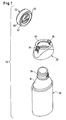
- Figure 1 is an exploded perspective view of a child resistant package of the prior art.
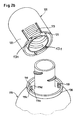
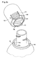
- Figures 2a to 2c are exploded perspective views of embodiments of child resistant packages according to the present invention.
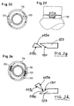
- Figures 2d and 2e are cross sectional top views of another child resistant package according to the present invention.
- Figure 2f is a front view of a child resistant package according to the present invention.
- Figures 2g and 2h are partial cross sectional views of the interlocking tooth and the pushtab, the pushtab further comprising a guiding ramp.
- Figure 2i is a perspective view of an embodiment of a closure of a child resistant package according to the present invention.
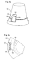
- Figure 3a is a front view of the upper portion of another embodiment of a child resistant package according to the present invention.
- Figure 3b illustrates cross sectional top view of the upper portion of another child resistant package according to the present invention.
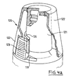
- Figure 4a is a front view, partially cut through the thickness, of an embodiment of a closure of a child resistant package according to the present invention.
- Figure 4b is a cross sectional side view of an embodiment of a closure of a child resistant package according to the present invention.
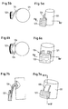
- Figure 5a shows a partial front view of another embodiment of a closure of a child resistant package according to the present invention.
- Figure 5b is a cross sectional top view taken along line (A,A') of Figure 5a.
- Figure 6a shows a partial front view of another embodiment of a closure of a child resistant package according to the present invention.
- Figure 6b is a cross sectional top view taken along line (A,A') of Figure 6a.
- Figure 7a shows a partial front view of another embodiment of a closure of a child resistant package according to the present invention.
- Figure 7b is a cross sectional top view taken along line (B,B') of Figure 7a.
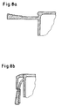
- Figures 8a and 8b show partial cross sectional front views of another embodiment of a closure of a child resistant package according to the present invention.
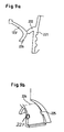
- Figure 9a is a cross sectional side view of another embodiment of a closure of a child resistant package according to the present invention.
- Figure 9b is a partial front view of the child resistant closure of Figure 9a.
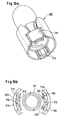
- Figure 10a is a perspective view of an embodiment of a closure of a child resistant package according to the present invention.
- Figure 10b is a cross section bottom view of the child resistant closure of Figure 10a.
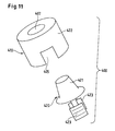
- Figure 11 is a perspective view of another embodiment of a closure of a child resistant package according to the present invention.
- Figure 12 is a cross sectional front view of another embodiment of a closure of a child resistant package according to the present invention.
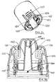
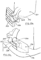
- Figure 13a is a perspective front view of another embodiment of a closure of a child resistant package according to the present invention which is shown in more detail in partial cuts in Figures 13b and 13c.
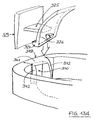
- Figure 13d is a partial cut of a variation of the closure of a child resistant package of Figures 13b and 13c.
- FIG. 1 An embodiment of a child resistant package (10) of the prior art is shown in an exploded perspective view in Figure 1.
- This package (10) is of the type generally disclosed in U.S. Patent 4,948,002 and comprises a bottle (12), a collar (32) and a closure (52).
- Said collar (32) is attached onto the shoulder portion (16) of said bottle, and said closure is releasably secured to the finish portion (18) of said bottle.
- a possible means for releasably secure said closure to said bottle is a combination of lugs and screw threads.
- Said collar comprises at least a pushtab (34) with a vertical extension (36) which projects above the top edge (40) of said collar.
- said pushtab (34) may also be preloaded. This means that said pushtab exerts a pressing force against the innermost surface of said outer skirt (60) when said closure (52) is fully threaded onto said finish portion (18) of said bottle (12). Indeed, in this manner the child resistance of the package (10) is increased without at the same time causing a substantial increase of difficulty to open the package by adults.
- the need to squeeze the pushtabs with one hand holding also the bottle, while the other hand is unscrewing the closure may be considered to be inconvenient and too complicated by the user. This may be the case, for example, when a package, due to its unwieldy external shape especially around said pushtabs in the upper portion of said package, needs a whole hand just to firmly hold said package.
- the difficulty to hold a package may be further increased by increasing the dimension and/or weight of said package. Indeed, it may be more difficult in this case to hold the package (10) at its upper portion and to depress concurrently with the same hand said pushtab of the child resistant closure as described in '002 and '286.
- said package may slip from the hand and fall on the ground, especially when elderly adults having impaired manual strength and dextrity try to handle such a package. Consequently, said package falling on the ground may break with a partial or complete loss of the content.
- the present invention provides a package comprising a child resistant closure which can be opened with only one hand.
- this is called “one hand operation”, in contrast to the “two hand operation” defined above.
- the package (100) according to the present invention comprising a container (Fig. 2a, 110) and a closure (Fig. 2a, 120).
- the container (110) according to the present invention comprises a hollow body (111).
- Said hollow body comprises a base wall (not shown), a side wall (114) and an upper portion (115).
- said container may further comprise a handle.
- said container (Fig. 2a, 110) is made of thermoplastic material.
- thermoplastic materials have been extensively described in the art and include vinyl chloride based resins, polymers and co-polymers derived from olefins, acrylic polymers and co-polymers, polyethylene, polypropylene, polystyrene, polyethylene terephthalate, polyethylene terephthalate glycol, or mixtures thereof.
- Said container can be made of single or multi-layer extrusion of such materials. It can also comprise recycled thermoplastic materials.
- a preferred thermoplastic material used herein is polyethylene.
- the form of said hollow body may be cylindrical, whereby the cross section in a plane parallel to the container's supporting plane is square or rectangular, ovoid or circular. Said supporting plane is the plane on which said container stands on its base wall in its upright position.
- Said upper portion (115) is located opposite to said base wall.
- Said upper portion comprises a shoulder portion (116), a neck portion (117) and at least one interlocking tooth (119).
- said upper portion may be a transition piece which is attached to said container.
- Said neck portion of said upper portion defines an opening (112).
- Said upper portion further comprises a first engaging means (118) for releasably securing said closure to said container.
- said first engaging means for releasably securing said closure to said container is located on said shoulder portion or on said neck portion.
- said first engaging means for releasably securing said closure to said container is a combination of lugs and screw threads located on the outermost surface of said upper portion.
- Another preferred first engaging means for releasably securing said closure to said container is a snapping mechanism comprising ribs and/or grooves also located on the outermost surface of said upper portion.
- Said neck portion may further comprise a spout (113) defining a reduced dispensing opening (151), as shown, for example, in Figure 4b.
- said spout is attached on said opening (112).
- Said spout comprises a channel (152) and attachment means. Said channel connects the interior of said container to said reduced dispensing opening.
- Said spout may be preferably attached on the innermost or outermost surface of said neck portion (117).
- Said attachment means between said spout and said neck portion may be achieved by threading or snapping mechanisms.
- said spout When said spout is attached to the outermost surface of said neck portion, said spout may further comprises said first engaging means being a threading or snapping mechanism.
- Said spout may further comprise the interlocking tooth (119).
- Said shoulder portion may be an integral part of said container.
- Said shoulder portion may also be a transition piece, like said spout (113), additionally attached to said container around said opening (112).
- said interlocking tooth (119) is positioned on said shoulder portion.
- said interlocking tooth comprises an inclined ramp (119a) and a radial wall (119b).
- said shoulder portion comprises at least a pair of interlocking teeth opposing each other.
- said shoulder portion may further comprise a surrounding wall (Fig. 2b, 130).
- said surrounding wall is concentrically aligned to said opening (112).
- Said interlocking tooth (119) may be a separate part, distanced from said surrounding wall (Fig. 2b), or may be part of the innermost or outermost surface of said surrounding wall (Fig. 2c and Fig. 2e).
- said surrounding wall may be interrupted with a cut through the thickness of said surrounding wall (Fig. 2d). The dimension of said cut is such to give complete access to said pushtab from the outside of said closure, at least partially accommodating said pushtab (123). In this case, said cut in said surrounding wall acts as an interlocking tooth, as illustrated in Figure 2d.
- said pushtab (123) has first to deflected inwardly towards said neck portion such that said pushtab is between said neck portion and said surrounding wall.
- said pushtab extends over the bottom edge (128) of said outer skirt (122) of said closure, as shown in Figure 2f.
- Said closure comprises an inner skirt (121), an outer skirt (122), a top wall (129) and at least a resiliently deformable pushtab (123).
- said closure may be also a measuring and dispensing cap.
- An example of a measuring and dispensing cap according to the present invention is shown in Figure 12.
- the measuring chamber is delimited by the surrounding wall (160).
- the part (161) of said surrounding wall plunges into said opening (112) of said container when said measuring and dispensing cap closes said container.
- Said measuring and dispensing cap further comprises said inner (121) and outer (122) skirt and at least a deformable pushtab (123).
- said second engaging means (118a) of said measuring and dispensing cap is on the innermost surface of said inner skirt.
- said pushtab further comprises a downward extension (127).
- Said inner or outer skirt comprises on at least one of its surfaces second engaging means (118a) complementary to said first engaging means (118) of said upper portion (115) for releasably securing said closure to said container.
- said second engaging means for releasably securing said closure to said container is a combination of lugs and screw threads or a snapping mechanism comprising ribs and/or grooves, corresponding to said first engaging means on said upper portion.
- said second engaging means for releasably securing said closure to said container is located on the innermost surface of said inner or outer skirt of said closure. The second engaging means for releasably securing said closure to said container ensures that said closure closes said container in a leak tight manner.
- said closure further comprises a plug (154) closing said reduced opening (151) of said spout.
- this plug fits into said reduced opening of said spout, as shown in Figure 4b.
- the plug statistics at least partially into said channel (152). In this manner, said plug further improves the leak tightness when said container is closed with said closure.
- said inner skirt (121) may be interrupted in correspondence of said pushtab (123) just behind said pushtab, as shown in Figure 2i.
- the interruption corresponds in dimension to the dimension of said pushtab.
- said pushtab can be deformed without being limited by an inner skirt which may act otherwise as a stopper.
- said inner skirt comprises partial second engaging means. Said inner skirt may be connected through the connecting walls (124) to said outer skirt.
- Said pushtab is the part of said closure interacting with said interlocking tooth (119).
- Said pushtab may be part or attached to said inner skirt (121) and/or to said outer skirt (122).
- Said pushtab has an exposed outermost surface contour which generally conforms to the exterior outermost surface contour of the adjacent portions of said outer skirt of said closure. This minimises the chance of inadvertent depression of said pushtab when said outer skirt is grasped.
- Said pushtab may be positioned anywhere on said outer skirt, e.g. at different distances from the top wall (129) of said closure. For example, said pushtab in Figure 4a is located away from said top wall, whereas in Figure 4b said pushtab is further towards said top wall.
- Figure 2a shows an embodiment of the present invention in which said pushtab is part of said outer skirt, and whereby said pushtab is formed by at least a pair of parallel slots (124, 124'). In this manner, said pushtab is fixed to said outer skirt along the drawn line (125) perpendicular to said slots. Therefore, said pushtab is cantilevered to said outer skirt of said closure.
- Figure 3a shows an embodiment of the present invention in which said pushtab is also part of said outer skirt, formed by three slots (124, 124' and 124'') and connected to said outer skirt through the transition portion (128).
- a spring (126) may be located between said inner skirt and said pushtab being part of said outer skirt, as illustrated, for example, in Figure 3b.
- said spring is made of a flexible and resilient arm (128).
- said spring is attached to or part of said inner skirt (121) at one end and attached to or leant against said pushtab at the opposite end of said flexible and resilient arm.
- said pushtab (123) may be independent from said outer skirt. Indeed, said pushtab and said inner skirt may be connected together with said spring (126), as shown, for example, in Figure 4a.
- Figure 4b illustrates an example in which at least the part of said inner skirt attached to said pushtab (123) is formed into an S-shaped spring (126).
- the S-shaped spring provides the flexibility and resiliency to said pushtab.
- said outer skirt (122) comprises a cut through the thickness of said outer skirt. Said cut has substantially the same dimension of said pushtab, giving complete access to said pushtab from the outside of said closure and fully accommodating said pushtab (123).
- Said spring (126) according to the present invention is not limited by any particular form of said spring. Indeed, said spring may be of several different forms, as shown in Figures 5 to 8.
- Figure 5a illustrates a perspective front view of a closure without said outer skirt, but showing said pushtab (123), said spring (126) and said inner skirt (121).
- said spring comprises one flexible and resilient arm (128).
- Figure 5b illustrates a cross sectional view taken across line (A-A') of Figure 5a.
- said flexible and resilient arm (128) may also be positioned perpendicularly, as shown in Figure 7a, with respect to the flexible and resilient arm (128) of Figure 5a.
- Figure 7b illustrates a cross sectional view across line (B-B') of Figure 7a.
- Figures 8a and 8b represent cross sectional views also across line (B-B') of Figure 7a, illustrating a preloaded pushtab (123).
- said flexible and resilient arm (128) is made substantially perpendicular to said inner skirt (121), as shown in Figure 8a.
- said outer skirt is made whereby said arm is bent downwards and kept by said outer skirt, as shown in Figure 8b.
- said spring (126) may comprise more than one flexible and resilient arm, as shown, for example, in Figures 6a and 6b. Preloading of said pushtab (123) may be achieved with any form of pushtab and/or spring (126) described before in Figures 5 to 7.
- FIGs 9a and 9b Another embodiment of a child resistant closure (200) with a preloaded pushtab (123') is shown in Figures 9a and 9b.
- Said closure (200) comprises said inner (221) and outer skirt (222).
- Said outer skirt further comprises a hinged pushtab (123'), said pushtab being hinged along the drawn line (Fig. 9b, 224).
- said pushtab may further comprise a spring (226).
- said pushtab and/or said outer skirt comprises at least a pair of lateral wings (Fig. 9b, 225).
- said flexible and resilient pushtab is made substantially perpendicular to said inner skirt (221), as shown in Figure 9a.
- said pushtab can be pushed down towards said outer skirt and locked within said outer skirt by said lateral wings, as shown in Figure 9b.
- said lateral wings impede that said pushtab springs back to the initial position of Figure 9a, i.e. said lateral wings maintain said pushtab locked within said outer skirt. Therefore, this allows to provide a preloaded pushtab.
- said lateral wings are located on said outer skirt, said lateral wings are over the outermost surface of said pushtab.
- said lateral wings press on the innermost surface of said outer skirt.
- said pushtab and/or said outer skirt may preferably further comprise recesses (227) corresponding to said lateral wings. Indeed, said lateral wings may seat within said recesses.
- preloading of said pushtab ensures positive locking with said interlocking tooth (119) even in situations where manufacturing tolerances drift beyond specific limits. If no preloading of said pushtab is present, drifts in manufacturing tolerance can reduce the required amount of travel for said pushtab and thereby permit disengaging of said closure (120) with less depression of said pushtab. Furthermore, we found that adults having impaired manual strength and dexterity do not find the preloading of said pushtab to pose any additional opening difficulty for them. Indeed, the level of preloading is not so great as to significantly increase the total force required to release said pushtab from said interlocking tooth and permit disengaging of said closure. Therefore, the adults are more prone to reapply said closure to said package once the desired amount of contents has been removed rather than leaving said closure only partially secured to or completely off of said package after initial opening.
- Said package (100) according to the present invention is closed and opened in the following manner.
- the maximum thickness of said pushtab (123) is greater compared to the thickness of the outer skirt (122).
- the pushtab which has a greater thickness with respect to the outer skirt, has to be deflected to pass around the interlocking tooth. In this case, the deflection of the pushtab may be helped by a guiding ramp (131).
- the guiding ramp is an inclined ramp located between the innermost and the outermost surface of the pushtab and on the part of the pushtab which first comes in contact with the interlocking tooth when the closure is screwed in the closing direction.
- the direction along the guiding ramp can be substantially parallel to the direction along the inclined wall (119a), as shown in a cross section view of Figure 2g.
- the edge (119e) which is the interconnecting edge between the inclined wall (119a) and the outermost surface (119c) of the interlocking tooth may point towards the guiding ramp, as shown in a cross section view of Figure 2h.
- Figures 2d, 2e and 4a illustrate the position of said pushtab, when said closure is fully threaded onto said container.
- Said radial wall (119b) of said interlocking tooth impedes that said pushtab may rotate in the reverse opening direction without first pushing inwardly onto said pushtab.
- said pushtabs must be inwardly depressed towards said dispensing opening (118) such that said pushtab disengage from said interlocking tooth.
- Said pushtab must be depressed until the thickness of said pushtab overcomes the innermost edge (119d) of said radial wall (119b). Now it is possible to turn said closure in the opening direction and to unscrew said closure from said container.
- the unscrewing of said closure from said container needs only a one-hand operation. Indeed, it is possible to grasp said closure (120) with one hand and at the same time to depress said pushtab(s) with one or two fingers of the same hand grasping said closure before turning said closure to open said package.
- This one-hand operation is allowed by the fact that said pushtab is positioned on said closure itself. Therefore, the other hand may be used only to hold said container without needing to interact in the opening operation.
- packages, which are uneasy to hold due to their unwieldy shape, especially when these packages have a large dimension and/or weight, comprising the child resistant closure according to the present invention can be firmly grasped and easily opened also by elderly adults having impaired manual strength and dextrity. Therefore, the risk of having said package slipped from the hand is substantially reduced.
- the squeezing force required to depress said pushtab(s) (123) is preferably great enough to be difficult for a child, yet low enough for adults, especially for elderly adults having impaired manual strength and dextrity, to readily depress said pushtab(s).
- the preferred squeezing force for said pushtab(s) is believed to be in the range of about 2.2 N (0.5 pounds) and about 22.2 (5 pounds).
- said pushtab(s) are preferably substantially flush with the outermost surface of said outer skirt (122) of said closure (120). In this manner, grasping said closure about its outer skirt is unlikely to permit said pushtab(s) from inadvertently disengaged from said interlocking teeth (119).
- Figure 2b illustrates an embodiment of said package according to the present invention comprising a surrounding wall (130). Said interlocking tooth is distanced and a separate part of said surrounding wall.
- said pushtab (123) has a greater thickness compared to the outer skirt (122). Consequently, the pushtab has to be deflected to pass around the interlocking tooth, as described for Figure 2a.
- the deflection of the pushtab may be helped by the guiding ramp (131), preferably by the guiding ramp as shown in Figure 2g. Consequently, the pushtab deflects in such a manner that the outermost surface of the pushtab passes behind the outermost surface (119c) of the interlocking tooth along the inclined ramp (119a), herein referred to as inward deflection.
- Said interlocking tooth (119) in Figure 2c is part of said surrounding wall (130).
- said pushtab (123) comprises a downward extension (127) instead of the guiding ramp (131) of Figures 2a and 2b.
- Said downward extension projects over the bottom edge (128) of said outer skirt (122) and is located between said outer and inner (121) skirt.
- said downward extension has to be inwardly pushed by depressing said pushtab until the thickness of said downward extension overcomes said innermost edge (119d) of said interlocking tooth.
- Figure 2e illustrates the same embodiment of Figure 2c further comprising two opposing interlocking teeth (119, 119'). This further opposing interlocking tooth (119') limits the movement of said pushtab once said closure is in its closing position. We found that this limited movement allowed in the closing position further discourages childs to open said closure.
- FIG. 10a Another preferred embodiment of a child resistant closure (300) according to the present invention is shown in Figure 10a.
- said pushtab (323) comprises an outer wall (Fig. 10b, 310) and an inner wall (312).
- Said inner wall is connected with said outer wall.
- said inner wall is connected with said outer wall through a connecting portion (314).
- a channel (315) is delimited by said inner wall, said outer wall and said connecting portion.
- Said interlocking tooth passes between said inner and outer wall of said pushtab through said channel (315).
- said inner wall of said pushtab is deflected principally upwards when pressing on said pushtab such that said inner wall of said pushtab passes over said interlocking tooth.
- the radial wall (119b) of said interlocking tooth has a height which decreases towards the edge (119d) of said radial wall. This decrease of the height of said radial wall facilitates the disengagement of said pushtab from said interlocking tooth.
- said radial wall (119b) of said interlocking tooth (119) impedes that said inner wall (314), and consequently said pushtab (323), may rotate in the reverse opening direction without any action on said pushtab.
- said pushtab to unscrew said closure (300) from said container, once said closure is fully assembled onto said shoulder portion (116), said pushtab must be inwardly depressed towards said dispensing opening (118) such that said inner wall (312) disengages from said interlocking tooth. Said pushtab must be depressed until the thickness of said inner wall overcomes the edge (119d) of said radial wall (119b). Now it is possible to turn said closure in the opening direction and to unscrew said closure from said container.
- said inner wall (314) may further comprise on its innermost surface a lateral wall (Fig. 10b, right half, 316) on each side of said inner wall (312).
- Said lateral wall is parallel to said inner wall and is located slightly behind said inner wall towards said neck portion (117) between said interlocking tooth and said neck portion (117) when said closure is in its closing position.
- Said lateral wall ensures that said inner wall of said pushtab passes on said inclined wall (119a) of said interlocking tooth when unscrewing said closure. Consequently, said interlocking tooth is obliged to pass through said channel (315). This may be especially useful when said shoulder portion (Fig. 2a, 116) does not comprise a surrounding wall (Fig. 2b, 130). Indeed, it may happen otherwise that said inner wall of said pushtab may pass on the outermost surface (119c) of said interlocking tooth without having to first deflect said pushtab bypassing the child resistance of said closure.
- FIG. 13a An example of a closure (310) according to the present invention comprising as first and second engaging means a snapping mechanism is shown in Figures 13a to 13d
- the outer shape of said closure in Figure 13a is similar to said closure shown in Figure 4a.
- Figure 13b illustrates said closure of Figure 13a without said outer skirt (322).
- Said closure comprises said inner skirt (321), said pushtab (323), an inner wall (312) of said pushtab similar to the inner wall described in Figures 10a 10b, a connecting part (325) connecting said pushtab to said inner wall of said pushtab and a lug (327).
- Said lug is an extension of said inner wall which interacts with said interlocking tooth (319), shown in Figure 13c, to achieve a child resistant closure of the package according to the present invention.
- Said interlocking tooth is located as before on the upper portion of said container. Specifically, said lug interacts with said interlocking tooth in such a manner that said closure cannot be pulled off from the corresponding container before said pushtab is pressed. Indeed, only when pushing on said pushtab allows said lug to get free from said interlocking tooth, and consequently to pull off said closure from said container.
- said lug and said interlocking tooth are made as shown in Figures 13c and 13d.
- Said lug comprises a lateral extension (328) comprising a flat upper wall (329).
- Said extension may have a cylindrical shape.
- said extension has a semi-rounded cylindrical shape as shown in Figures 13b and 13c which facilitates an easy snapping on of said closure on said container.
- Said interlocking tooth further comprises a roof (330) extending from the upper portion of said interlocking tooth.
- Said roof and said lug interact with each other in such a manner that said lug is located under said roof when said closure is in its closed position on said container. Consequently, in this position said closure cannot be simply pulled off from said container. Indeed, when trying to pull off said closure with an upward movement, said flat upper wall of said lug comes in interaction with the lower surface of said roof. Thereby a further upward movement of said closure is prevented.
- FIG. 13d Another preferred embodiment of the present invention is shown in Figure 13d.
- at least a lug (327) is located on said closure on the lower portion of said inner wall (312) between said pushtab (323) and said inner wall (312) and under said connecting part (325).
- Said lug interlocks in between the arc (340).
- the arc comprises a roof (341) limited by two colums (342).
- Said lug is again under said roof in between said columns when said closure is in its closed position on said container.
- To open said container the same principle as discussed before apply also in this case.
- said spring deflects inwardly towards said container, such that said lug snaps under said roof.
- Said closure (400) comprises a housing (410) and a fitment (420).
- Said housing comprises said outer skirt and cuts through the thickness of said housing corresponding to the location of said two pushtabs (423).
- Said fitment further comprises said inner skirt (421) and said two pushtabs.
- Said fitment is inserted inside said housing to complete the closure (400) which can be applied onto a container according to the present invention.
- said housing has an upper hole (407) and said fitment comprises a hat (421) passing at least partially through said upper hole (407).
- said fitment provides the closure of said container.
- said closure (120) is made of thermoplastic material.
- thermoplastic materials have been extensively described in the art and include vinyl chloride based resins, polymers and co-polymers derived from olefins acrylic polymers and co-polymers, polyethylene, polypropylene, polystyrene, polyethylene terephthalate, polyethylene terephthalate glycol, or mixtures thereof.
- Said closure can be made of single or multi-layer extrusion of such materials. It can also comprise recycled thermoplastic materials.
- a preferred thermoplastic material used herein is polypropylene.
- Different parts of said closure like said pushtab (123) or said spring (126), may be made of a different thermoplastic material than said inner (121) or outer skirt (122).
- thermoplastic material may be co-injected together. Indeed, we found that said pushtab or spring of different forms or of a different material with respect to the rest of said closure allows to vary the flexibility of said pushtab, i.e. to vary the force needed to be applied on said pushtab.
- said package (100) according to the present invention may further comprise a pilferproof system.
- the pilfer-proof system enables the user to check when buying the package according to the present invention filled with a product that said package has not been opened before by someone else.
- Said pilferproof system may be achieved with break-off spurs (140) or with a pull-out ring (145).
- Said break-off spurs attach said closure (120) to said shoulder portion (116). This attachment achieved with said break-off spurs is easily broken off when said package is opened for the first time.
- Said pull-out cover is a cover over said opening (112) or reduced opening (151). Consequently, the access to the content of said package can be achieved only after uncovering said opening from said pull-off cover.
- said pull-off cover further comprises a ring extending from said pull-off cover. Said ring facilitates the uncovering of said opening from said pull-off cover. Indeed, the user may insert a finger in said ring, and consequently pull-off said cover.
- Said package (100) according to the present invention is suitable for storing and dispensing potentially dangerous products.
- Potentially dangerous products are products which may hurt the health of children and adults when not used in a conscious manner and with the correct dosage.
- Medicaments and cleaning products are, for example, such products. These products may be in solid, tablet, granular, powdered, semi-solid, paste or liquid form.
- said package according to the present invention contains liquid cleaning products, like a hard surface cleaner or a toilet bowl cleaner.
Landscapes
- Engineering & Computer Science (AREA)
- Mechanical Engineering (AREA)
- Closures For Containers (AREA)
- Cartons (AREA)
- Containers Opened By Tearing Frangible Portions (AREA)
- Packages (AREA)
Priority Applications (10)
| Application Number | Priority Date | Filing Date | Title |
|---|---|---|---|
| EP19950203583 EP0751078B1 (fr) | 1995-06-28 | 1995-12-21 | Emballage de protection vis-à-vis des enfants, mais facile à manipuler pour les adultes |
| US08/981,376 US6036036A (en) | 1995-06-28 | 1996-06-04 | Adult friendly child-resistant package |
| PCT/US1996/008670 WO1997001494A1 (fr) | 1995-06-28 | 1996-06-04 | Emballage de securite pour enfants, facile a utiliser pour les adultes |
| BR9609388A BR9609388A (pt) | 1995-06-28 | 1996-06-04 | Embalagem resistente a criança e conveniente para o adulto |
| CA002225251A CA2225251C (fr) | 1995-06-28 | 1996-06-04 | Emballage de securite pour enfants, facile a utiliser pour les adultes |
| AU59784/96A AU5978496A (en) | 1995-06-28 | 1996-06-04 | An adult friendly child-resistant package |
| MX9800198A MX9800198A (es) | 1995-06-28 | 1996-06-04 | Envase resistente a niños, facilmente manipulable por un adulto. |
| JP50442297A JP3904603B2 (ja) | 1995-06-28 | 1996-06-04 | 大人に扱いやすく子供に耐性のあるパッケージ |
| TW085107772A TW324701B (en) | 1995-06-28 | 1996-06-27 | A package easy for an adult to open, but that prevents a child from opening it |
| ARP960103363A AR002628A1 (es) | 1995-06-28 | 1996-06-28 | Envase resistente a ninos y facil de abrir para adultos. |
Applications Claiming Priority (3)
| Application Number | Priority Date | Filing Date | Title |
|---|---|---|---|
| EP95201764 | 1995-06-28 | ||
| EP95201764 | 1995-06-28 | ||
| EP19950203583 EP0751078B1 (fr) | 1995-06-28 | 1995-12-21 | Emballage de protection vis-à-vis des enfants, mais facile à manipuler pour les adultes |
Publications (3)
| Publication Number | Publication Date |
|---|---|
| EP0751078A2 true EP0751078A2 (fr) | 1997-01-02 |
| EP0751078A3 EP0751078A3 (fr) | 1997-08-27 |
| EP0751078B1 EP0751078B1 (fr) | 2001-11-14 |
Family
ID=26139442
Family Applications (1)
| Application Number | Title | Priority Date | Filing Date |
|---|---|---|---|
| EP19950203583 Expired - Lifetime EP0751078B1 (fr) | 1995-06-28 | 1995-12-21 | Emballage de protection vis-à-vis des enfants, mais facile à manipuler pour les adultes |
Country Status (9)
| Country | Link |
|---|---|
| EP (1) | EP0751078B1 (fr) |
| JP (1) | JP3904603B2 (fr) |
| AR (1) | AR002628A1 (fr) |
| AU (1) | AU5978496A (fr) |
| BR (1) | BR9609388A (fr) |
| CA (1) | CA2225251C (fr) |
| MX (1) | MX9800198A (fr) |
| TW (1) | TW324701B (fr) |
| WO (1) | WO1997001494A1 (fr) |
Cited By (9)
| Publication number | Priority date | Publication date | Assignee | Title |
|---|---|---|---|---|
| FR2758800A1 (fr) * | 1997-01-30 | 1998-07-31 | Astra Plastique | Dispositif servant de temoin a la bonne fermeture d'un bouchon a vis |
| GB2311062B (en) * | 1995-10-31 | 1999-11-10 | Kerr Group Inc | Child-resistant container and closure assembly |
| EP1092643A1 (fr) * | 1999-10-12 | 2001-04-18 | Owens-Illinois Closure Inc. | Fermeture de sécurité pour enfants à pression et à vissage et son procédé de fabrication |
| DE10006370A1 (de) * | 2000-02-12 | 2001-08-16 | Pfeiffer Erich Gmbh & Co Kg | Austragvorrichtung für Medien |
| EP1975079A1 (fr) * | 2007-03-27 | 2008-10-01 | Petrolia AB | Capuchon de sécurité pour protéger les enfants avec fonction de ventilation |
| WO2008141163A1 (fr) * | 2007-05-11 | 2008-11-20 | Alcan Global Pharmaceutical Packaging Inc. | Fermeture monobloc à presser et à tourner à l'épreuve des enfants, et système de contenant |
| WO2017214072A1 (fr) * | 2016-06-06 | 2017-12-14 | The Procter & Gamble Company | Fermetures compressibles |
| WO2017214071A1 (fr) * | 2016-06-06 | 2017-12-14 | The Procter & Gamble Company | Systèmes de contenants à fermeture par pression et rotation |
| DE102022111669A1 (de) | 2022-05-10 | 2023-11-16 | Georg Menshen Gmbh & Co. Kg | Ausgießvorrichtung |
Families Citing this family (10)
| Publication number | Priority date | Publication date | Assignee | Title |
|---|---|---|---|---|
| DE29621083U1 (de) * | 1996-12-04 | 1998-04-02 | Joh. Winklhofer & Söhne GmbH und Co KG, 81369 München | Gedämpftes Kettenrad |
| US6988642B2 (en) * | 2002-10-29 | 2006-01-24 | Johnson & Johnson Consumer Companies | Tamper-evident dispenser bottle |
| TWI343233B (en) | 2007-10-19 | 2011-06-01 | Au Optronics Corp | Circuit board assembly and backlight module comprising the same |
| GB0721998D0 (en) * | 2007-11-09 | 2007-12-19 | Shipbuilding Co Ltd | Lightweight child resistant package |
| KR101479069B1 (ko) * | 2014-01-22 | 2015-01-07 | (주)연우 | 측면 가압식 안전캡 |
| PT3102501T (pt) * | 2014-02-03 | 2018-06-04 | Cellpack Ag | Fecho de recipiente |
| US10343827B2 (en) * | 2017-01-02 | 2019-07-09 | Innovative Product Brands, Inc. | Child-resistant locking cap for laminated tubes |
| GB201806853D0 (en) * | 2018-04-26 | 2018-06-13 | Obrist Closures Switzerland | A closure |
| ES2967968T3 (es) * | 2018-09-13 | 2024-05-06 | Aptargroup Inc | Cierre para un recipiente |
| CN116969050A (zh) * | 2023-07-31 | 2023-10-31 | 上海民宁科技有限公司 | 一种背负式油箱 |
Citations (2)
| Publication number | Priority date | Publication date | Assignee | Title |
|---|---|---|---|---|
| US4948002A (en) | 1988-12-29 | 1990-08-14 | The Procter & Gamble Company | Package exhibiting improved child resistance without significantly impeding access by adults |
| WO1992007286A1 (fr) | 1990-10-15 | 1992-04-30 | Plymouth Française | Dispositif detectable pour l'identification d'objets optiquement invisibles |
Family Cites Families (14)
| Publication number | Priority date | Publication date | Assignee | Title |
|---|---|---|---|---|
| US541015A (en) * | 1895-06-11 | Pneumatic collar-pad | ||
| GB1387572A (en) * | 1973-04-05 | 1975-03-19 | Sunbeam Plastics Corp | Safety closure |
| US3917097A (en) * | 1974-06-03 | 1975-11-04 | Gerhardt E Uhlig | Safety closure container |
| US3989152A (en) * | 1976-02-09 | 1976-11-02 | Sunbeam Plastics Corporation | Child-resistant locking means for a twist-action container cap |
| US4149646A (en) * | 1978-06-21 | 1979-04-17 | Sunbeam Plastics Corporation | Child-resistant locking means for a container |
| US4429800A (en) * | 1982-06-01 | 1984-02-07 | Greenspan Donald J | Child safe container-closure unit |
| US4752014A (en) * | 1987-12-16 | 1988-06-21 | Poly-Seal Corporation | Tamper-evident child-resistant closure and container with same |
| US4865209A (en) * | 1988-07-25 | 1989-09-12 | Sunbeam Plastics Corporation | Child resistant closure |
| FR2636310A1 (fr) * | 1988-09-13 | 1990-03-16 | Sunbeam Plastics Corp | Bouchon distributeur en deux pieces a l'epreuve des enfants et emballage a recipient et bouchon |
| FR2660911B1 (fr) * | 1990-04-13 | 1992-07-03 | Astra Plastique | Dispositif de bouchage a capuchon tournant. |
| US5078288A (en) * | 1990-10-30 | 1992-01-07 | Owens-Illinois Closure Inc. | Child resistant spout package |
| FR2676997B1 (fr) * | 1991-05-29 | 1993-08-27 | Novembal Sa | Bouchon-service a l'epreuve des enfants. |
| HK1006162A1 (en) * | 1991-10-07 | 1999-02-12 | The Procter & Gamble Company | Child-resistant package having preloaded locking mechanism |
| US5230433A (en) * | 1992-01-28 | 1993-07-27 | The Procter & Gamble Company | Adult friendly child-resistant attachment for containers used to store potentially dangerous materials |
-
1995
- 1995-12-21 EP EP19950203583 patent/EP0751078B1/fr not_active Expired - Lifetime
-
1996
- 1996-06-04 CA CA002225251A patent/CA2225251C/fr not_active Expired - Fee Related
- 1996-06-04 JP JP50442297A patent/JP3904603B2/ja not_active Expired - Fee Related
- 1996-06-04 BR BR9609388A patent/BR9609388A/pt not_active Application Discontinuation
- 1996-06-04 AU AU59784/96A patent/AU5978496A/en not_active Abandoned
- 1996-06-04 WO PCT/US1996/008670 patent/WO1997001494A1/fr not_active Ceased
- 1996-06-04 MX MX9800198A patent/MX9800198A/es unknown
- 1996-06-27 TW TW085107772A patent/TW324701B/zh active
- 1996-06-28 AR ARP960103363A patent/AR002628A1/es unknown
Patent Citations (2)
| Publication number | Priority date | Publication date | Assignee | Title |
|---|---|---|---|---|
| US4948002A (en) | 1988-12-29 | 1990-08-14 | The Procter & Gamble Company | Package exhibiting improved child resistance without significantly impeding access by adults |
| WO1992007286A1 (fr) | 1990-10-15 | 1992-04-30 | Plymouth Française | Dispositif detectable pour l'identification d'objets optiquement invisibles |
Cited By (10)
| Publication number | Priority date | Publication date | Assignee | Title |
|---|---|---|---|---|
| GB2311062B (en) * | 1995-10-31 | 1999-11-10 | Kerr Group Inc | Child-resistant container and closure assembly |
| US6357615B1 (en) | 1995-10-31 | 2002-03-19 | Kerr Group, Inc. | Child-resistant one-piece container and one-piece closure |
| FR2758800A1 (fr) * | 1997-01-30 | 1998-07-31 | Astra Plastique | Dispositif servant de temoin a la bonne fermeture d'un bouchon a vis |
| EP1092643A1 (fr) * | 1999-10-12 | 2001-04-18 | Owens-Illinois Closure Inc. | Fermeture de sécurité pour enfants à pression et à vissage et son procédé de fabrication |
| DE10006370A1 (de) * | 2000-02-12 | 2001-08-16 | Pfeiffer Erich Gmbh & Co Kg | Austragvorrichtung für Medien |
| EP1975079A1 (fr) * | 2007-03-27 | 2008-10-01 | Petrolia AB | Capuchon de sécurité pour protéger les enfants avec fonction de ventilation |
| WO2008141163A1 (fr) * | 2007-05-11 | 2008-11-20 | Alcan Global Pharmaceutical Packaging Inc. | Fermeture monobloc à presser et à tourner à l'épreuve des enfants, et système de contenant |
| WO2017214072A1 (fr) * | 2016-06-06 | 2017-12-14 | The Procter & Gamble Company | Fermetures compressibles |
| WO2017214071A1 (fr) * | 2016-06-06 | 2017-12-14 | The Procter & Gamble Company | Systèmes de contenants à fermeture par pression et rotation |
| DE102022111669A1 (de) | 2022-05-10 | 2023-11-16 | Georg Menshen Gmbh & Co. Kg | Ausgießvorrichtung |
Also Published As
| Publication number | Publication date |
|---|---|
| MX9800198A (es) | 1998-04-30 |
| TW324701B (en) | 1998-01-11 |
| BR9609388A (pt) | 1999-05-18 |
| WO1997001494A1 (fr) | 1997-01-16 |
| JP3904603B2 (ja) | 2007-04-11 |
| AR002628A1 (es) | 1998-03-25 |
| EP0751078B1 (fr) | 2001-11-14 |
| CA2225251C (fr) | 2003-02-11 |
| JPH11508520A (ja) | 1999-07-27 |
| AU5978496A (en) | 1997-01-30 |
| CA2225251A1 (fr) | 1997-01-16 |
| EP0751078A3 (fr) | 1997-08-27 |
Similar Documents
| Publication | Publication Date | Title |
|---|---|---|
| US6036036A (en) | Adult friendly child-resistant package | |
| EP0751078B1 (fr) | Emballage de protection vis-à-vis des enfants, mais facile à manipuler pour les adultes | |
| US5979681A (en) | Child resistant attachment for containers | |
| US5230433A (en) | Adult friendly child-resistant attachment for containers used to store potentially dangerous materials | |
| US6612450B1 (en) | Reversible cap | |
| CA2208549C (fr) | Ensemble recipient et fermeture de securite pour enfant | |
| US5158194A (en) | Safety closure with easy-open feature for handicapped and elderly individuals | |
| CA2120713C (fr) | Emballage de securite pour les enfants avec mecanisme de verrouillage prealablement active | |
| MXPA98000198A (en) | Children resistant container, easily manipulated by an adu | |
| HK1006162B (en) | Child-resistant package having preloaded locking mechanism | |
| US5586671A (en) | Child resistant package | |
| WO1997023388A1 (fr) | Emballage a l'epreuve de l'ouverture par des enfants, d'emploi facile pour les adultes | |
| EP0780318B1 (fr) | Emballage à l'épreuve des enfants, facile d'emploi pour les adultes | |
| EP0780317B1 (fr) | Récipient muni d'une fermeture comportant une pièce intermédiaire et protégée vis-à-vis des enfants | |
| EP0711240B1 (fr) | Emballage inviolable par les enfants | |
| GB2307229A (en) | A safety closure for re-fillable containers |
Legal Events
| Date | Code | Title | Description |
|---|---|---|---|
| PUAI | Public reference made under article 153(3) epc to a published international application that has entered the european phase |
Free format text: ORIGINAL CODE: 0009012 |
|
| AK | Designated contracting states |
Kind code of ref document: A2 Designated state(s): DE FR GB IT LU |
|
| PUAL | Search report despatched |
Free format text: ORIGINAL CODE: 0009013 |
|
| 17P | Request for examination filed |
Effective date: 19970623 |
|
| AK | Designated contracting states |
Kind code of ref document: A3 Designated state(s): AT BE CH DE DK ES FR GB GR IE IT LI LU NL PT SE |
|
| 17Q | First examination report despatched |
Effective date: 19990317 |
|
| GRAG | Despatch of communication of intention to grant |
Free format text: ORIGINAL CODE: EPIDOS AGRA |
|
| GRAG | Despatch of communication of intention to grant |
Free format text: ORIGINAL CODE: EPIDOS AGRA |
|
| GRAH | Despatch of communication of intention to grant a patent |
Free format text: ORIGINAL CODE: EPIDOS IGRA |
|
| RBV | Designated contracting states (corrected) |
Designated state(s): DE FR GB IT LU |
|
| GRAH | Despatch of communication of intention to grant a patent |
Free format text: ORIGINAL CODE: EPIDOS IGRA |
|
| GRAA | (expected) grant |
Free format text: ORIGINAL CODE: 0009210 |
|
| AK | Designated contracting states |
Kind code of ref document: B1 Designated state(s): DE FR GB IT LU |
|
| REF | Corresponds to: |
Ref document number: 69523905 Country of ref document: DE Date of ref document: 20011220 |
|
| PG25 | Lapsed in a contracting state [announced via postgrant information from national office to epo] |
Ref country code: LU Free format text: LAPSE BECAUSE OF NON-PAYMENT OF DUE FEES Effective date: 20011221 |
|
| REG | Reference to a national code |
Ref country code: GB Ref legal event code: IF02 |
|
| PLBE | No opposition filed within time limit |
Free format text: ORIGINAL CODE: 0009261 |
|
| STAA | Information on the status of an ep patent application or granted ep patent |
Free format text: STATUS: NO OPPOSITION FILED WITHIN TIME LIMIT |
|
| 26N | No opposition filed | ||
| PGFP | Annual fee paid to national office [announced via postgrant information from national office to epo] |
Ref country code: GB Payment date: 20101123 Year of fee payment: 16 |
|
| PGFP | Annual fee paid to national office [announced via postgrant information from national office to epo] |
Ref country code: FR Payment date: 20111205 Year of fee payment: 17 |
|
| PGFP | Annual fee paid to national office [announced via postgrant information from national office to epo] |
Ref country code: DE Payment date: 20111230 Year of fee payment: 17 |
|
| PGFP | Annual fee paid to national office [announced via postgrant information from national office to epo] |
Ref country code: IT Payment date: 20111228 Year of fee payment: 17 |
|
| GBPC | Gb: european patent ceased through non-payment of renewal fee |
Effective date: 20121221 |
|
| REG | Reference to a national code |
Ref country code: FR Ref legal event code: ST Effective date: 20130830 |
|
| REG | Reference to a national code |
Ref country code: DE Ref legal event code: R119 Ref document number: 69523905 Country of ref document: DE Effective date: 20130702 |
|
| PG25 | Lapsed in a contracting state [announced via postgrant information from national office to epo] |
Ref country code: DE Free format text: LAPSE BECAUSE OF NON-PAYMENT OF DUE FEES Effective date: 20130702 |
|
| PG25 | Lapsed in a contracting state [announced via postgrant information from national office to epo] |
Ref country code: GB Free format text: LAPSE BECAUSE OF NON-PAYMENT OF DUE FEES Effective date: 20121221 Ref country code: FR Free format text: LAPSE BECAUSE OF NON-PAYMENT OF DUE FEES Effective date: 20130102 |
|
| PG25 | Lapsed in a contracting state [announced via postgrant information from national office to epo] |
Ref country code: IT Free format text: LAPSE BECAUSE OF NON-PAYMENT OF DUE FEES Effective date: 20121221 |