EP0751094A1 - Unter Schwerkraft arbeitende Abgabevorrichtung mit verbesserter Schliesseinrichtung - Google Patents
Unter Schwerkraft arbeitende Abgabevorrichtung mit verbesserter Schliesseinrichtung Download PDFInfo
- Publication number
- EP0751094A1 EP0751094A1 EP96304806A EP96304806A EP0751094A1 EP 0751094 A1 EP0751094 A1 EP 0751094A1 EP 96304806 A EP96304806 A EP 96304806A EP 96304806 A EP96304806 A EP 96304806A EP 0751094 A1 EP0751094 A1 EP 0751094A1
- Authority
- EP
- European Patent Office
- Prior art keywords
- dispensing orifice
- projection
- dispensing
- fluid
- ridge
- Prior art date
- Legal status (The legal status is an assumption and is not a legal conclusion. Google has not performed a legal analysis and makes no representation as to the accuracy of the status listed.)
- Granted
Links
- 230000005484 gravity Effects 0.000 title abstract description 7
- 239000012530 fluid Substances 0.000 claims abstract description 23
- 230000035939 shock Effects 0.000 abstract description 10
- 239000007921 spray Substances 0.000 abstract description 10
- 239000012141 concentrate Substances 0.000 abstract description 5
- 239000003085 diluting agent Substances 0.000 abstract description 2
- POIUWJQBRNEFGX-XAMSXPGMSA-N cathelicidin Chemical compound C([C@@H](C(=O)N[C@@H](CCCNC(N)=N)C(=O)N[C@@H](CCCCN)C(=O)N[C@@H](CO)C(=O)N[C@@H](CCCCN)C(=O)N[C@@H](CCC(O)=O)C(=O)N[C@@H](CCCCN)C(=O)N[C@@H]([C@@H](C)CC)C(=O)NCC(=O)N[C@@H](CCCCN)C(=O)N[C@@H](CCC(O)=O)C(=O)N[C@@H](CC=1C=CC=CC=1)C(=O)N[C@@H](CCCCN)C(=O)N[C@@H](CCCNC(N)=N)C(=O)N[C@@H]([C@@H](C)CC)C(=O)N[C@@H](C(C)C)C(=O)N[C@@H](CCC(N)=O)C(=O)N[C@@H](CCCNC(N)=N)C(=O)N[C@@H]([C@@H](C)CC)C(=O)N[C@@H](CCCCN)C(=O)N[C@@H](CC(O)=O)C(=O)N[C@@H](CC=1C=CC=CC=1)C(=O)N[C@@H](CC(C)C)C(=O)N[C@@H](CCCNC(N)=N)C(=O)N[C@@H](CC(N)=O)C(=O)N[C@@H](CC(C)C)C(=O)N[C@@H](C(C)C)C(=O)N1[C@@H](CCC1)C(=O)N[C@@H](CCCNC(N)=N)C(=O)N[C@@H]([C@@H](C)O)C(=O)N[C@@H](CCC(O)=O)C(=O)N[C@@H](CO)C(O)=O)NC(=O)[C@H](CC=1C=CC=CC=1)NC(=O)[C@H](CC(O)=O)NC(=O)CNC(=O)[C@H](CC(C)C)NC(=O)[C@@H](N)CC(C)C)C1=CC=CC=C1 POIUWJQBRNEFGX-XAMSXPGMSA-N 0.000 description 4
- 239000003518 caustics Substances 0.000 description 1
- 230000007423 decrease Effects 0.000 description 1
- 230000000694 effects Effects 0.000 description 1
- 231100001261 hazardous Toxicity 0.000 description 1
- 230000003993 interaction Effects 0.000 description 1
- 239000007788 liquid Substances 0.000 description 1
- 230000001105 regulatory effect Effects 0.000 description 1
- 239000000126 substance Substances 0.000 description 1
Images

Classifications
-
- B—PERFORMING OPERATIONS; TRANSPORTING
- B67—OPENING, CLOSING OR CLEANING BOTTLES, JARS OR SIMILAR CONTAINERS; LIQUID HANDLING
- B67D—DISPENSING, DELIVERING OR TRANSFERRING LIQUIDS, NOT OTHERWISE PROVIDED FOR
- B67D3/00—Apparatus or devices for controlling flow of liquids under gravity from storage containers for dispensing purposes
- B67D3/04—Liquid-dispensing taps or cocks adapted to seal and open tapping holes of casks, e.g. for beer
- B67D3/043—Liquid-dispensing taps or cocks adapted to seal and open tapping holes of casks, e.g. for beer with a closing element having a linear movement, in a direction perpendicular to the seat
- B67D3/044—Liquid-dispensing taps or cocks adapted to seal and open tapping holes of casks, e.g. for beer with a closing element having a linear movement, in a direction perpendicular to the seat and venting means operated automatically with the tap
-
- B—PERFORMING OPERATIONS; TRANSPORTING
- B67—OPENING, CLOSING OR CLEANING BOTTLES, JARS OR SIMILAR CONTAINERS; LIQUID HANDLING
- B67D—DISPENSING, DELIVERING OR TRANSFERRING LIQUIDS, NOT OTHERWISE PROVIDED FOR
- B67D3/00—Apparatus or devices for controlling flow of liquids under gravity from storage containers for dispensing purposes
- B67D3/0019—Apparatus or devices for controlling flow of liquids under gravity from storage containers for dispensing purposes using ingredient cartridges
Definitions
- the present invention relates to dispensers in general, and more particularly to an improved gravity dispenser for dispensing, inter alia , a concentrate to be mixed with a diluent.
- the present invention includes a feature for reducing spray caused by closing of a flow control valve.
- U.S. Patent No. 4,570,830 describes a gravity dispenser device which allows controlled dispensing of a fluid, particularly a concentrate, at a predetermined flow rate.
- the flow rate of fluid out of a dispensing orifice is controlled by regulating the location of an air-egress point in the fluid container using a variable-position valve mechanism. Cutouts which define the air-egress points can be moved axially in the container, changing the pressure head to which the fluid at the dispensing orifice is subject. This variation in the pressure head thereby controls the flow rate of fluid from the container through the dispensing orifice.
- the device of U.S. Patent No. 4,570,830 contains mutually-coacting surfaces which are used to shut off the valve and prevent fluid dispensing. As shown in U.S. Patent No. 4,570,830, an O-ring or an annular seal contacts one of the horizontal surfaces of the valve adjacent the dispensing orifice, to thereby effect shut-off.
- One disadvantage of the valve shut-off feature of the device shown in U.S. Patent No. 4,570,830 is that as the mutually-coacting surfaces approach each other prior to shut-off, the volume of the area between the surfaces decreases, increasing the pressure of any fluid trapped between the two surfaces. This increasing fluid pressure results in a fluid shock wave which, when it enters the dispensing orifice, can cause undesirable spray at the dispensing orifice. Such spray is particularly disadvantageous when the fluid being dispensing is a potentially hazardous or caustic chemical concentrate.
- the object of the present invention is accomplished by including a raised projection or ridge on one of the two coacting surface which engage one another to provide shut-off at the dispensing orifice.
- This projection or ridge causes any fluid shock wave located between the coacting surfaces to be directed away from the projection or ridge as the coacting surfaces approach each other, thereby biasing the shock wave away from the dispensing orifice.
- the projection or ridge includes chamfering at its edges which also acts to reduce or eliminate spray by directing the fluid shock wave away from the dispensing orifice.
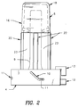
- the dispensing device 1 of the present invention includes a container 2 which holds, inter alia , a fluid concentrate.
- the container 2 includes an outlet end 3 into which is affixed a flow control valve 4 and is sealed at the top, such that entry of air into container 2 is only through the operation of the valve 4 described below.
- Flow control valve 4 includes two relatively-moving parts -- a moving element 5 and a fixed element 6 .
- moving element 5 and fixed element 6 are described below as being, respectively, fixed and movable, it is to be understood that relative movement between the two causes valve operation, and that therefore the "fixed” element could move while the "moving" element is fixed could be used to cause valve operation.
- Moving element 5 includes a dispensing orifice 7 through which fluid within container 2 is dispensed.
- the dispensing orifice 7 is adjacent a lower horizontal surface 14 .
- Moving element 5 also includes an air-inlet orifice 8 and an air inlet tube 9 .
- Moving element 5 has on a radial periphery a series of slots 10 which cooperate with pegs 11 on fixed element 6 to allow moving element 5 to move axially relative to fixed element 6 .
- moving element 5 includes a projection 12 which cooperates with a projection 13 on fixed element 6 to assist with relative movement of moving 5 and fixed 6 elements.
- Fixed element 6 includes a lower portion 15 and an upper portion 16 .
- Lower portion 15 includes pegs 11 which fit inside slots 10 on moving element 5 to allow moving element 5 to move rotationally as well as axially relative to fixed element 6 .
- the slots 10 are generally sloped to thereby allow the pegs 11 -- and thereby the moving element 5 -- to move axially up and down as the moving element 5 is rotated relative to the fixed element 6 .
- a projection 12 on moving element 5 can be engaged, either manually or automatically, to thereby rotate moving element 5 relative to fixed element 6 . This rotational movement, in conjunction with the sloped shape of slots 10 , causes axial movement of the moving element 5 relative to the fixed element 6 .
- Air inlet orifice 8 and air inlet tube 9 allow the ingress of air from the atmosphere into a chamber 17 .
- Chamber 17 is formed by a cap 18 defining the upper portion 16 of fixed element 6 .
- Cap 18 is connected to lower portion 15 by a series of stanchions 22 which form air egress slots 23 for egress of air into container 2 .
- a baffle 19 secured to cap 18 forms the lower boundary of chamber 17 .
- Air entering chamber 17 through air inlet orifice 8 and air inlet tube 9 passes into chamber 17 and exits chamber 17 through an air egress opening 20 between baffle 19 and air inlet tube 9 . Air escaping from air egress opening 20 enters container 2 .
- Lower portion 15 of fixed element 6 includes an upper horizontal surface 21 .
- Lower horizontal surface 14 and upper horizontal surface 21 cooperate to close dispensing orifice 7 when surfaces 14 and 21 contact one another. Contact of surfaces 14 and 21 is caused by axial movement of moving element 5 relative to fixed element 6 until such contact between surfaces 14 and 21 occurs. The resulting contact causes a seal between the surfaces 14 , 21 such that fluid in container 2 cannot pass to dispensing orifice 7 .
- Fixed element may also include a seal element 50 in the form of an O-ring or the like, which seals the outlet end 3 of container 2 to the valve 4 .
- a rim 51 can be used, with pins 11 and slots 12 to secure the fixed 6 and moving 5 elements to one another.
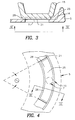
- upper horizontal surface 21 on fixed element 6 includes a projection or ridge 25 .
- Projection or ridge 25 covers an arc ⁇ of approximately 90° along the horizontal surface 21 , and in the position in which surfaces 14 and 21 are contacting, the dispensing orifice 7 is approximately centered under the projection or ridge 25 (Fig. 4).
- Projection or ridge 25 includes a bevelled or chamfered edge 26 .
- tangential force applied to projection 12 in the direction into the paper in Fig. 2, causes moving element 5 to rotate, and because of the interaction between pegs 11 and slot 10 , causes the surfaces 14 and 21 to move away from one another.
- This movement creates a space between the surfaces 14 and 21 , allowing fluid to flow through the space and out dispensing orifice 7 .
- Air enters the container 2 through the orifice 8 , tube 9 , chamber 17 and opening 20 .
- the flow rate of liquid through dispensing orifice 7 is controlled by the height of the pressure head created in valve 3 , which is in turn controlled by the inlet point of air into container 2 relative to the position of the dispensing orifice 7 .
- the pressure head increases and the flow rate out dispensing orifice 7 increases.
- Shut-off of the valve 4 proceeds as follows. Rotation of moving element 5 as the result of a tangential force applied to projection 12 , in the direction out of the paper in Fig. 2 , results in axial movement of surfaces 14 and 21 towards one another. This movement also causes projection or ridge 25 to sweep over the area above dispensing orifice 7 . As the surfaces 14 and 21 move towards one another, a fluid shock wave is created in the space between these surfaces, which shock wave is pushed away from the area of the dispensing orifice 7 by the projection or ridge 25 , including the bevelled or chamfered edge 26 of projection or ridge 25 .
- the fluid shock wave does not approach dispensing orifice 7 as the surfaces 14 and 17 contact one another, thereby reducing or eliminating any spray out dispensing orifice 7 that would otherwise be caused by the shock wave reaching dispensing orifice 7 .
- the present invention contemplates a number of different variations on the above-described preferred embodiment. It is to be understood that the above description is only of one preferred embodiment, and that other valve designs may be used with the present invention, as well as other designs of the ridge or projection for reducing or eliminating spray. The scope of the invention is to be measured by the claims as set forth below.
Landscapes
- Engineering & Computer Science (AREA)
- Mechanical Engineering (AREA)
- Containers And Packaging Bodies Having A Special Means To Remove Contents (AREA)
- Reciprocating Pumps (AREA)
- Closures For Containers (AREA)
- Devices For Dispensing Beverages (AREA)
- Nozzles (AREA)
Applications Claiming Priority (2)
| Application Number | Priority Date | Filing Date | Title |
|---|---|---|---|
| US08/497,658 US5775550A (en) | 1995-06-30 | 1995-06-30 | Gravity dispenser with improved shut-off feature |
| US497658 | 1995-06-30 |
Publications (2)
| Publication Number | Publication Date |
|---|---|
| EP0751094A1 true EP0751094A1 (de) | 1997-01-02 |
| EP0751094B1 EP0751094B1 (de) | 1999-01-27 |
Family
ID=23977765
Family Applications (1)
| Application Number | Title | Priority Date | Filing Date |
|---|---|---|---|
| EP96304806A Expired - Lifetime EP0751094B1 (de) | 1995-06-30 | 1996-06-28 | Unter Schwerkraft arbeitende Abgabevorrichtung mit verbesserter Schliesseinrichtung |
Country Status (7)
| Country | Link |
|---|---|
| US (1) | US5775550A (de) |
| EP (1) | EP0751094B1 (de) |
| JP (1) | JPH09100000A (de) |
| AT (1) | ATE176214T1 (de) |
| CA (1) | CA2180185A1 (de) |
| DE (1) | DE69601445T2 (de) |
| ES (1) | ES2129928T3 (de) |
Families Citing this family (8)
| Publication number | Priority date | Publication date | Assignee | Title |
|---|---|---|---|---|
| AUPP600398A0 (en) * | 1998-09-17 | 1998-10-08 | Kilian, Michael | Dispensing lid |
| AU757531B2 (en) * | 1998-09-17 | 2003-02-27 | Oil Safe Systems Pty Ltd | Dispensing lid |
| US6527950B2 (en) | 1999-10-14 | 2003-03-04 | Chiaphua Industries Limited | Construction of a water treatment appliance |
| US6361686B1 (en) | 1999-10-14 | 2002-03-26 | Fantom Technologies Inc. | Construction of a water treatment reservoir for a domestic water treatment appliance |
| US6491815B2 (en) | 1999-10-14 | 2002-12-10 | Chiaphua Industrires Limited | Construction of a water treatment reservoir for a domestic water treatment appliance |
| WO2013126663A1 (en) * | 2012-02-24 | 2013-08-29 | The Coca-Cola Company | Mechanical dispensing system |
| US11116364B1 (en) * | 2020-08-07 | 2021-09-14 | Malcomb Davis | Gravity based soap dispenser |
| US11684149B2 (en) | 2021-03-25 | 2023-06-27 | Malcomb Davis | Paint brush cleaning system |
Citations (3)
| Publication number | Priority date | Publication date | Assignee | Title |
|---|---|---|---|---|
| EP0080261A2 (de) * | 1981-10-09 | 1983-06-01 | Cadbury Schweppes Limited | Flüssigkeitszapfverpackung und -ventil |
| US4570830A (en) * | 1983-06-28 | 1986-02-18 | Cadbury Schweppes, Plc | Gravity dispenser |
| US5211314A (en) * | 1991-12-27 | 1993-05-18 | Ebtech, Inc. | Syrup dispenser and valve assembly |
Family Cites Families (11)
| Publication number | Priority date | Publication date | Assignee | Title |
|---|---|---|---|---|
| GB437007A (en) * | 1935-03-01 | 1935-10-22 | Bryngel Lindbeck | Improvements in and relating to collapsible tubes |
| GB471230A (en) * | 1935-11-12 | 1937-08-31 | Kurt Wolter | Improvements in containers, such as collapsible tubes, with screw-on caps |
| NL53229C (de) * | 1937-01-29 | |||
| US4523697A (en) * | 1979-07-11 | 1985-06-18 | Cadbury Schweppes Limited | Liquid dispensing package |
| US4635824A (en) * | 1985-09-13 | 1987-01-13 | The Coca-Cola Company | Low-cost post-mix beverage dispenser and syrup supply system therefor |
| US4712713A (en) * | 1985-11-20 | 1987-12-15 | Cadbury Schweppes, Plc | Gas cylinder coupling and weighting mechanism for a carbonated drink dispenser |
| US5251789A (en) * | 1985-11-20 | 1993-10-12 | Cadbury Schweppes, Plc | In-home drink dispenser |
| US5118010A (en) * | 1985-11-20 | 1992-06-02 | Cadbury Schweppes, Plc | In-home drink dispenser |
| GB8611389D0 (en) * | 1986-05-09 | 1986-06-18 | Cadbury Schweppes Plc | Carbonating apparatus |
| US4804117A (en) * | 1986-10-14 | 1989-02-14 | The Coca-Cola Company | Disposable syrup package having integral disposable valve assembly |
| US5172831A (en) * | 1991-12-23 | 1992-12-22 | Ebtech, Inc. | Valve actuator for a soft drink dispenser station |
-
1995
- 1995-06-30 US US08/497,658 patent/US5775550A/en not_active Expired - Fee Related
-
1996
- 1996-06-28 DE DE69601445T patent/DE69601445T2/de not_active Expired - Fee Related
- 1996-06-28 EP EP96304806A patent/EP0751094B1/de not_active Expired - Lifetime
- 1996-06-28 AT AT96304806T patent/ATE176214T1/de not_active IP Right Cessation
- 1996-06-28 CA CA002180185A patent/CA2180185A1/en not_active Abandoned
- 1996-06-28 JP JP8169703A patent/JPH09100000A/ja active Pending
- 1996-06-28 ES ES96304806T patent/ES2129928T3/es not_active Expired - Lifetime
Patent Citations (3)
| Publication number | Priority date | Publication date | Assignee | Title |
|---|---|---|---|---|
| EP0080261A2 (de) * | 1981-10-09 | 1983-06-01 | Cadbury Schweppes Limited | Flüssigkeitszapfverpackung und -ventil |
| US4570830A (en) * | 1983-06-28 | 1986-02-18 | Cadbury Schweppes, Plc | Gravity dispenser |
| US5211314A (en) * | 1991-12-27 | 1993-05-18 | Ebtech, Inc. | Syrup dispenser and valve assembly |
Also Published As
| Publication number | Publication date |
|---|---|
| JPH09100000A (ja) | 1997-04-15 |
| ATE176214T1 (de) | 1999-02-15 |
| CA2180185A1 (en) | 1996-12-31 |
| EP0751094B1 (de) | 1999-01-27 |
| DE69601445T2 (de) | 1999-06-02 |
| US5775550A (en) | 1998-07-07 |
| ES2129928T3 (es) | 1999-06-16 |
| DE69601445D1 (de) | 1999-03-11 |
Similar Documents
| Publication | Publication Date | Title |
|---|---|---|
| US3341082A (en) | Dispensing device with purging means | |
| CA1264707A (en) | Liquid dispensing device | |
| US4998649A (en) | Retractable turnspout closure | |
| EP0751094B1 (de) | Unter Schwerkraft arbeitende Abgabevorrichtung mit verbesserter Schliesseinrichtung | |
| CA1275386C (en) | Twist cap having adjustable flow rate | |
| KR950700128A (ko) | 각 패턴에 대해 자동조절되는 최적 펌프 행정으로 액체를 상이한 스프레이 패턴으로 스프레이하기 위해 복수 오리피스를 이용하는 스프레이 펌프 패키지(spray pump package employing multiple orifices for dispensing liquid in different spray patterns with automatically adjusted optimized pump stroke for each pattern) | |
| JPH0298593A (ja) | 飲料分配システムのための装置 | |
| EP0590100B1 (de) | Flasche und ventilanordnung | |
| WO1994027881A1 (en) | Dropper dispenser | |
| KR960703353A (ko) | 일체식 수송용 밀봉부를 갖는 절첩식 펌프실을 구비한 펌프장치(Pump device with collapsible pump chamber having integral shipping seal) | |
| EP0264115B1 (de) | Einwegverpackung für Sirup mit integriertem Ventil | |
| EP0963324B1 (de) | Abgabeverschluss | |
| US20030132254A1 (en) | Automatic actuator for aerosol valves | |
| EP0238494B1 (de) | Flüssigkeitsbehälter | |
| KR920010081B1 (ko) | 음료자동판매기용 시럽패키지 | |
| EP0690750B1 (de) | Schaumerzeugungseinheit, sowie sprühkopf und sprühdose mit einer solchen einheit | |
| US5524864A (en) | Check valve made of plastic | |
| US5067638A (en) | Device for dispensing measures of a given volume of a liquid contained in a deformable container comprising a safety element | |
| CA2106846A1 (en) | Closure element | |
| KR200388440Y1 (ko) | 토출량 조절용 디스펜서 | |
| GB2252098A (en) | Dispensing nozzle with cut-off valve | |
| CA1211385A (en) | Dispensing device for liquids | |
| WO1999044904A8 (en) | Metering device | |
| EP0111812B1 (de) | Zapfventil | |
| US3554410A (en) | Aerosol dispenser with spray nozzle at bottom thereof |
Legal Events
| Date | Code | Title | Description |
|---|---|---|---|
| PUAI | Public reference made under article 153(3) epc to a published international application that has entered the european phase |
Free format text: ORIGINAL CODE: 0009012 |
|
| AK | Designated contracting states |
Kind code of ref document: A1 Designated state(s): AT BE CH DE DK ES FI FR GB GR IE IT LI LU MC NL PT SE |
|
| 17P | Request for examination filed |
Effective date: 19970509 |
|
| 17Q | First examination report despatched |
Effective date: 19970721 |
|
| GRAG | Despatch of communication of intention to grant |
Free format text: ORIGINAL CODE: EPIDOS AGRA |
|
| GRAG | Despatch of communication of intention to grant |
Free format text: ORIGINAL CODE: EPIDOS AGRA |
|
| GRAH | Despatch of communication of intention to grant a patent |
Free format text: ORIGINAL CODE: EPIDOS IGRA |
|
| GRAH | Despatch of communication of intention to grant a patent |
Free format text: ORIGINAL CODE: EPIDOS IGRA |
|
| GRAA | (expected) grant |
Free format text: ORIGINAL CODE: 0009210 |
|
| AK | Designated contracting states |
Kind code of ref document: B1 Designated state(s): AT BE CH DE DK ES FI FR GB GR IE IT LI LU MC NL PT SE |
|
| PG25 | Lapsed in a contracting state [announced via postgrant information from national office to epo] |
Ref country code: GR Free format text: LAPSE BECAUSE OF NON-PAYMENT OF DUE FEES Effective date: 19990127 Ref country code: FI Free format text: LAPSE BECAUSE OF NON-PAYMENT OF DUE FEES Effective date: 19990127 |
|
| REF | Corresponds to: |
Ref document number: 176214 Country of ref document: AT Date of ref document: 19990215 Kind code of ref document: T |
|
| REG | Reference to a national code |
Ref country code: CH Ref legal event code: EP |
|
| ITF | It: translation for a ep patent filed | ||
| ET | Fr: translation filed | ||
| REG | Reference to a national code |
Ref country code: IE Ref legal event code: FG4D |
|
| REF | Corresponds to: |
Ref document number: 69601445 Country of ref document: DE Date of ref document: 19990311 |
|
| NLR4 | Nl: receipt of corrected translation in the netherlands language at the initiative of the proprietor of the patent | ||
| PG25 | Lapsed in a contracting state [announced via postgrant information from national office to epo] |
Ref country code: PT Free format text: LAPSE BECAUSE OF FAILURE TO SUBMIT A TRANSLATION OF THE DESCRIPTION OR TO PAY THE FEE WITHIN THE PRESCRIBED TIME-LIMIT Effective date: 19990427 Ref country code: DK Free format text: LAPSE BECAUSE OF FAILURE TO SUBMIT A TRANSLATION OF THE DESCRIPTION OR TO PAY THE FEE WITHIN THE PRESCRIBED TIME-LIMIT Effective date: 19990427 |
|
| REG | Reference to a national code |
Ref country code: CH Ref legal event code: NV Representative=s name: E. BLUM & CO. PATENTANWAELTE |
|
| REG | Reference to a national code |
Ref country code: ES Ref legal event code: FG2A Ref document number: 2129928 Country of ref document: ES Kind code of ref document: T3 |
|
| PGFP | Annual fee paid to national office [announced via postgrant information from national office to epo] |
Ref country code: MC Payment date: 19990629 Year of fee payment: 4 |
|
| PGFP | Annual fee paid to national office [announced via postgrant information from national office to epo] |
Ref country code: IE Payment date: 19990630 Year of fee payment: 4 |
|
| PGFP | Annual fee paid to national office [announced via postgrant information from national office to epo] |
Ref country code: DK Payment date: 19990714 Year of fee payment: 4 |
|
| PGFP | Annual fee paid to national office [announced via postgrant information from national office to epo] |
Ref country code: LU Payment date: 19990715 Year of fee payment: 4 |
|
| PLBE | No opposition filed within time limit |
Free format text: ORIGINAL CODE: 0009261 |
|
| STAA | Information on the status of an ep patent application or granted ep patent |
Free format text: STATUS: NO OPPOSITION FILED WITHIN TIME LIMIT |
|
| 26N | No opposition filed | ||
| PGFP | Annual fee paid to national office [announced via postgrant information from national office to epo] |
Ref country code: FR Payment date: 20000612 Year of fee payment: 5 |
|
| PGFP | Annual fee paid to national office [announced via postgrant information from national office to epo] |
Ref country code: AT Payment date: 20000613 Year of fee payment: 5 |
|
| PGFP | Annual fee paid to national office [announced via postgrant information from national office to epo] |
Ref country code: SE Payment date: 20000626 Year of fee payment: 5 Ref country code: DE Payment date: 20000626 Year of fee payment: 5 |
|
| PG25 | Lapsed in a contracting state [announced via postgrant information from national office to epo] |
Ref country code: LU Free format text: LAPSE BECAUSE OF NON-PAYMENT OF DUE FEES Effective date: 20000628 Ref country code: IE Free format text: LAPSE BECAUSE OF NON-PAYMENT OF DUE FEES Effective date: 20000628 |
|
| PGFP | Annual fee paid to national office [announced via postgrant information from national office to epo] |
Ref country code: GB Payment date: 20000628 Year of fee payment: 5 Ref country code: CH Payment date: 20000628 Year of fee payment: 5 |
|
| PGFP | Annual fee paid to national office [announced via postgrant information from national office to epo] |
Ref country code: NL Payment date: 20000629 Year of fee payment: 5 |
|
| PG25 | Lapsed in a contracting state [announced via postgrant information from national office to epo] |
Ref country code: MC Free format text: THE PATENT HAS BEEN ANNULLED BY A DECISION OF A NATIONAL AUTHORITY Effective date: 20000630 |
|
| PGFP | Annual fee paid to national office [announced via postgrant information from national office to epo] |
Ref country code: ES Payment date: 20000720 Year of fee payment: 5 |
|
| PGFP | Annual fee paid to national office [announced via postgrant information from national office to epo] |
Ref country code: BE Payment date: 20000818 Year of fee payment: 5 |
|
| REG | Reference to a national code |
Ref country code: IE Ref legal event code: MM4A |
|
| PG25 | Lapsed in a contracting state [announced via postgrant information from national office to epo] |
Ref country code: GB Free format text: LAPSE BECAUSE OF NON-PAYMENT OF DUE FEES Effective date: 20010628 Ref country code: AT Free format text: LAPSE BECAUSE OF NON-PAYMENT OF DUE FEES Effective date: 20010628 |
|
| PG25 | Lapsed in a contracting state [announced via postgrant information from national office to epo] |
Ref country code: SE Free format text: LAPSE BECAUSE OF NON-PAYMENT OF DUE FEES Effective date: 20010629 Ref country code: ES Free format text: LAPSE BECAUSE OF NON-PAYMENT OF DUE FEES Effective date: 20010629 |
|
| PG25 | Lapsed in a contracting state [announced via postgrant information from national office to epo] |
Ref country code: LI Free format text: LAPSE BECAUSE OF NON-PAYMENT OF DUE FEES Effective date: 20010630 Ref country code: CH Free format text: LAPSE BECAUSE OF NON-PAYMENT OF DUE FEES Effective date: 20010630 Ref country code: BE Free format text: LAPSE BECAUSE OF NON-PAYMENT OF DUE FEES Effective date: 20010630 |
|
| BERE | Be: lapsed |
Owner name: TOLL DUNCAN M. Effective date: 20010630 |
|
| PG25 | Lapsed in a contracting state [announced via postgrant information from national office to epo] |
Ref country code: NL Free format text: LAPSE BECAUSE OF NON-PAYMENT OF DUE FEES Effective date: 20020101 |
|
| EUG | Se: european patent has lapsed |
Ref document number: 96304806.1 |
|
| REG | Reference to a national code |
Ref country code: CH Ref legal event code: PL |
|
| GBPC | Gb: european patent ceased through non-payment of renewal fee |
Effective date: 20010628 |
|
| PG25 | Lapsed in a contracting state [announced via postgrant information from national office to epo] |
Ref country code: FR Free format text: LAPSE BECAUSE OF NON-PAYMENT OF DUE FEES Effective date: 20020228 |
|
| NLV4 | Nl: lapsed or anulled due to non-payment of the annual fee |
Effective date: 20020101 |
|
| PG25 | Lapsed in a contracting state [announced via postgrant information from national office to epo] |
Ref country code: DE Free format text: LAPSE BECAUSE OF NON-PAYMENT OF DUE FEES Effective date: 20020403 |
|
| REG | Reference to a national code |
Ref country code: ES Ref legal event code: FD2A Effective date: 20030303 |
|
| PG25 | Lapsed in a contracting state [announced via postgrant information from national office to epo] |
Ref country code: IT Free format text: LAPSE BECAUSE OF NON-PAYMENT OF DUE FEES Effective date: 20050628 |