EP0751411A1 - Koppelröhrchen für optische Fasern, Methode zu seiner Herstellung und Methode zur Verbindung optischer Fasern - Google Patents
Koppelröhrchen für optische Fasern, Methode zu seiner Herstellung und Methode zur Verbindung optischer Fasern Download PDFInfo
- Publication number
- EP0751411A1 EP0751411A1 EP96109992A EP96109992A EP0751411A1 EP 0751411 A1 EP0751411 A1 EP 0751411A1 EP 96109992 A EP96109992 A EP 96109992A EP 96109992 A EP96109992 A EP 96109992A EP 0751411 A1 EP0751411 A1 EP 0751411A1
- Authority
- EP
- European Patent Office
- Prior art keywords
- connecting member
- optical fibers
- optical fiber
- fiber connecting
- hole
- Prior art date
- Legal status (The legal status is an assumption and is not a legal conclusion. Google has not performed a legal analysis and makes no representation as to the accuracy of the status listed.)
- Withdrawn
Links
- 239000013307 optical fiber Substances 0.000 title claims abstract description 256
- 238000000034 method Methods 0.000 title claims abstract description 72
- 230000008878 coupling Effects 0.000 title 1
- 238000010168 coupling process Methods 0.000 title 1
- 238000005859 coupling reaction Methods 0.000 title 1
- 239000011521 glass Substances 0.000 claims abstract description 103
- 238000010438 heat treatment Methods 0.000 claims abstract description 28
- VYPSYNLAJGMNEJ-UHFFFAOYSA-N Silicium dioxide Chemical compound O=[Si]=O VYPSYNLAJGMNEJ-UHFFFAOYSA-N 0.000 claims description 32
- 239000000853 adhesive Substances 0.000 claims description 13
- 239000000463 material Substances 0.000 claims description 12
- 238000010891 electric arc Methods 0.000 claims description 11
- 125000002887 hydroxy group Chemical group [H]O* 0.000 claims description 8
- PXGOKWXKJXAPGV-UHFFFAOYSA-N Fluorine Chemical compound FF PXGOKWXKJXAPGV-UHFFFAOYSA-N 0.000 claims description 7
- 229910052731 fluorine Inorganic materials 0.000 claims description 7
- 239000011737 fluorine Substances 0.000 claims description 7
- ZAMOUSCENKQFHK-UHFFFAOYSA-N Chlorine atom Chemical compound [Cl] ZAMOUSCENKQFHK-UHFFFAOYSA-N 0.000 claims description 6
- 229910052801 chlorine Inorganic materials 0.000 claims description 6
- 239000000460 chlorine Substances 0.000 claims description 6
- 238000005520 cutting process Methods 0.000 claims description 6
- 239000012943 hotmelt Substances 0.000 claims description 6
- 230000008569 process Effects 0.000 claims description 4
- 238000013459 approach Methods 0.000 claims description 2
- 230000002787 reinforcement Effects 0.000 claims description 2
- RTAQQCXQSZGOHL-UHFFFAOYSA-N Titanium Chemical compound [Ti] RTAQQCXQSZGOHL-UHFFFAOYSA-N 0.000 claims 1
- 229910052681 coesite Inorganic materials 0.000 claims 1
- 229910052906 cristobalite Inorganic materials 0.000 claims 1
- 239000000377 silicon dioxide Substances 0.000 claims 1
- 229910052682 stishovite Inorganic materials 0.000 claims 1
- 229910052719 titanium Inorganic materials 0.000 claims 1
- 239000010936 titanium Substances 0.000 claims 1
- 229910052905 tridymite Inorganic materials 0.000 claims 1
- 238000007526 fusion splicing Methods 0.000 abstract 1
- 230000004927 fusion Effects 0.000 description 20
- 238000003780 insertion Methods 0.000 description 16
- 230000037431 insertion Effects 0.000 description 16
- 239000000654 additive Substances 0.000 description 11
- 230000003287 optical effect Effects 0.000 description 10
- GWEVSGVZZGPLCZ-UHFFFAOYSA-N Titan oxide Chemical compound O=[Ti]=O GWEVSGVZZGPLCZ-UHFFFAOYSA-N 0.000 description 8
- 230000008859 change Effects 0.000 description 8
- 230000015572 biosynthetic process Effects 0.000 description 7
- 239000000835 fiber Substances 0.000 description 6
- 238000004519 manufacturing process Methods 0.000 description 6
- 238000000227 grinding Methods 0.000 description 5
- 238000012545 processing Methods 0.000 description 5
- YBMRDBCBODYGJE-UHFFFAOYSA-N germanium dioxide Chemical compound O=[Ge]=O YBMRDBCBODYGJE-UHFFFAOYSA-N 0.000 description 4
- 239000004408 titanium dioxide Substances 0.000 description 4
- 238000004891 communication Methods 0.000 description 3
- 230000007246 mechanism Effects 0.000 description 3
- 239000000203 mixture Substances 0.000 description 3
- 239000005304 optical glass Substances 0.000 description 3
- 229910003910 SiCl4 Inorganic materials 0.000 description 2
- 238000005286 illumination Methods 0.000 description 2
- 238000005498 polishing Methods 0.000 description 2
- 230000003014 reinforcing effect Effects 0.000 description 2
- 235000012239 silicon dioxide Nutrition 0.000 description 2
- FDNAPBUWERUEDA-UHFFFAOYSA-N silicon tetrachloride Chemical compound Cl[Si](Cl)(Cl)Cl FDNAPBUWERUEDA-UHFFFAOYSA-N 0.000 description 2
- VZGDMQKNWNREIO-UHFFFAOYSA-N tetrachloromethane Chemical compound ClC(Cl)(Cl)Cl VZGDMQKNWNREIO-UHFFFAOYSA-N 0.000 description 2
- KZBUYRJDOAKODT-UHFFFAOYSA-N Chlorine Chemical compound ClCl KZBUYRJDOAKODT-UHFFFAOYSA-N 0.000 description 1
- 229910004014 SiF4 Inorganic materials 0.000 description 1
- 229910003074 TiCl4 Inorganic materials 0.000 description 1
- 239000011248 coating agent Substances 0.000 description 1
- 238000000576 coating method Methods 0.000 description 1
- 230000007423 decrease Effects 0.000 description 1
- 238000011161 development Methods 0.000 description 1
- 239000002019 doping agent Substances 0.000 description 1
- 230000007062 hydrolysis Effects 0.000 description 1
- 238000006460 hydrolysis reaction Methods 0.000 description 1
- 238000005304 joining Methods 0.000 description 1
- 230000014759 maintenance of location Effects 0.000 description 1
- 239000013308 plastic optical fiber Substances 0.000 description 1
- 239000010453 quartz Substances 0.000 description 1
- 239000002994 raw material Substances 0.000 description 1
- 230000009467 reduction Effects 0.000 description 1
- 238000000926 separation method Methods 0.000 description 1
- ABTOQLMXBSRXSM-UHFFFAOYSA-N silicon tetrafluoride Chemical compound F[Si](F)(F)F ABTOQLMXBSRXSM-UHFFFAOYSA-N 0.000 description 1
- 238000003980 solgel method Methods 0.000 description 1
- XJDNKRIXUMDJCW-UHFFFAOYSA-J titanium tetrachloride Chemical compound Cl[Ti](Cl)(Cl)Cl XJDNKRIXUMDJCW-UHFFFAOYSA-J 0.000 description 1
- XLYOFNOQVPJJNP-UHFFFAOYSA-N water Chemical compound O XLYOFNOQVPJJNP-UHFFFAOYSA-N 0.000 description 1
Images







Classifications
-
- G—PHYSICS
- G02—OPTICS
- G02B—OPTICAL ELEMENTS, SYSTEMS OR APPARATUS
- G02B6/00—Light guides; Structural details of arrangements comprising light guides and other optical elements, e.g. couplings
- G02B6/24—Coupling light guides
- G02B6/255—Splicing of light guides, e.g. by fusion or bonding
- G02B6/2558—Reinforcement of splice joint
-
- C—CHEMISTRY; METALLURGY
- C03—GLASS; MINERAL OR SLAG WOOL
- C03B—MANUFACTURE, SHAPING, OR SUPPLEMENTARY PROCESSES
- C03B37/00—Manufacture or treatment of flakes, fibres, or filaments from softened glass, minerals, or slags
- C03B37/01—Manufacture of glass fibres or filaments
- C03B37/012—Manufacture of preforms for drawing fibres or filaments
- C03B37/01205—Manufacture of preforms for drawing fibres or filaments starting from tubes, rods, fibres or filaments
-
- G—PHYSICS
- G02—OPTICS
- G02B—OPTICAL ELEMENTS, SYSTEMS OR APPARATUS
- G02B6/00—Light guides; Structural details of arrangements comprising light guides and other optical elements, e.g. couplings
- G02B6/24—Coupling light guides
- G02B6/255—Splicing of light guides, e.g. by fusion or bonding
- G02B6/2551—Splicing of light guides, e.g. by fusion or bonding using thermal methods, e.g. fusion welding by arc discharge, laser beam, plasma torch
-
- G—PHYSICS
- G02—OPTICS
- G02B—OPTICAL ELEMENTS, SYSTEMS OR APPARATUS
- G02B6/00—Light guides; Structural details of arrangements comprising light guides and other optical elements, e.g. couplings
- G02B6/24—Coupling light guides
- G02B6/255—Splicing of light guides, e.g. by fusion or bonding
- G02B6/2555—Alignment or adjustment devices for aligning prior to splicing
-
- G—PHYSICS
- G02—OPTICS
- G02B—OPTICAL ELEMENTS, SYSTEMS OR APPARATUS
- G02B6/00—Light guides; Structural details of arrangements comprising light guides and other optical elements, e.g. couplings
- G02B6/24—Coupling light guides
- G02B6/36—Mechanical coupling means
- G02B6/3628—Mechanical coupling means for mounting fibres to supporting carriers
- G02B6/3632—Mechanical coupling means for mounting fibres to supporting carriers characterised by the cross-sectional shape of the mechanical coupling means
- G02B6/3636—Mechanical coupling means for mounting fibres to supporting carriers characterised by the cross-sectional shape of the mechanical coupling means the mechanical coupling means being grooves
-
- G—PHYSICS
- G02—OPTICS
- G02B—OPTICAL ELEMENTS, SYSTEMS OR APPARATUS
- G02B6/00—Light guides; Structural details of arrangements comprising light guides and other optical elements, e.g. couplings
- G02B6/24—Coupling light guides
- G02B6/36—Mechanical coupling means
- G02B6/3628—Mechanical coupling means for mounting fibres to supporting carriers
- G02B6/3632—Mechanical coupling means for mounting fibres to supporting carriers characterised by the cross-sectional shape of the mechanical coupling means
- G02B6/3644—Mechanical coupling means for mounting fibres to supporting carriers characterised by the cross-sectional shape of the mechanical coupling means the coupling means being through-holes or wall apertures
-
- G—PHYSICS
- G02—OPTICS
- G02B—OPTICAL ELEMENTS, SYSTEMS OR APPARATUS
- G02B6/00—Light guides; Structural details of arrangements comprising light guides and other optical elements, e.g. couplings
- G02B6/24—Coupling light guides
- G02B6/36—Mechanical coupling means
- G02B6/3628—Mechanical coupling means for mounting fibres to supporting carriers
- G02B6/3648—Supporting carriers of a microbench type, i.e. with micromachined additional mechanical structures
- G02B6/3652—Supporting carriers of a microbench type, i.e. with micromachined additional mechanical structures the additional structures being prepositioning mounting areas, allowing only movement in one dimension, e.g. grooves, trenches or vias in the microbench surface, i.e. self aligning supporting carriers
-
- G—PHYSICS
- G02—OPTICS
- G02B—OPTICAL ELEMENTS, SYSTEMS OR APPARATUS
- G02B6/00—Light guides; Structural details of arrangements comprising light guides and other optical elements, e.g. couplings
- G02B6/24—Coupling light guides
- G02B6/36—Mechanical coupling means
- G02B6/3628—Mechanical coupling means for mounting fibres to supporting carriers
- G02B6/3664—2D cross sectional arrangements of the fibres
-
- G—PHYSICS
- G02—OPTICS
- G02B—OPTICAL ELEMENTS, SYSTEMS OR APPARATUS
- G02B6/00—Light guides; Structural details of arrangements comprising light guides and other optical elements, e.g. couplings
- G02B6/24—Coupling light guides
- G02B6/36—Mechanical coupling means
- G02B6/3628—Mechanical coupling means for mounting fibres to supporting carriers
- G02B6/3664—2D cross sectional arrangements of the fibres
- G02B6/3672—2D cross sectional arrangements of the fibres with fibres arranged in a regular matrix array
-
- G—PHYSICS
- G02—OPTICS
- G02B—OPTICAL ELEMENTS, SYSTEMS OR APPARATUS
- G02B6/00—Light guides; Structural details of arrangements comprising light guides and other optical elements, e.g. couplings
- G02B6/24—Coupling light guides
- G02B6/36—Mechanical coupling means
- G02B6/3628—Mechanical coupling means for mounting fibres to supporting carriers
- G02B6/3684—Mechanical coupling means for mounting fibres to supporting carriers characterised by the manufacturing process of surface profiling of the supporting carrier
-
- G—PHYSICS
- G02—OPTICS
- G02B—OPTICAL ELEMENTS, SYSTEMS OR APPARATUS
- G02B6/00—Light guides; Structural details of arrangements comprising light guides and other optical elements, e.g. couplings
- G02B6/24—Coupling light guides
- G02B6/36—Mechanical coupling means
- G02B6/38—Mechanical coupling means having fibre to fibre mating means
- G02B6/3807—Dismountable connectors, i.e. comprising plugs
- G02B6/3833—Details of mounting fibres in ferrules; Assembly methods; Manufacture
- G02B6/3834—Means for centering or aligning the light guide within the ferrule
- G02B6/3838—Means for centering or aligning the light guide within the ferrule using grooves for light guides
- G02B6/3839—Means for centering or aligning the light guide within the ferrule using grooves for light guides for a plurality of light guides
-
- G—PHYSICS
- G02—OPTICS
- G02B—OPTICAL ELEMENTS, SYSTEMS OR APPARATUS
- G02B6/00—Light guides; Structural details of arrangements comprising light guides and other optical elements, e.g. couplings
- G02B6/24—Coupling light guides
- G02B6/36—Mechanical coupling means
- G02B6/38—Mechanical coupling means having fibre to fibre mating means
- G02B6/3807—Dismountable connectors, i.e. comprising plugs
- G02B6/3833—Details of mounting fibres in ferrules; Assembly methods; Manufacture
- G02B6/3855—Details of mounting fibres in ferrules; Assembly methods; Manufacture characterised by the method of anchoring or fixing the fibre within the ferrule
- G02B6/3862—Details of mounting fibres in ferrules; Assembly methods; Manufacture characterised by the method of anchoring or fixing the fibre within the ferrule radially-compressed, longitudinally-split ferrules consisting of a pair of identical matching halves
Definitions
- the present invention relates to an optical fiber connecting member for forming optical connecting by facing end portions of optical fibers each other, a method of producing the optical fiber connecting member, and a method of connecting optical fibers.
- optical fiber connecting has been required to satisfy low loss, low cost, high reliability and easiness of connecting.
- a fusion connecting method for fusing end portions of optical fibers with each other and a mechanical connecting method for retaining end portions of optical fibers merely in a physically facing state have been mainly developed as a stationary optical fiber connecting method for forming an optical communication network.
- fusion connecting method there is generally known a method in which heat-fusion is performed by means of arc discharge, or the like, after planishing connecting end surfaces of single-core or multi-core optical fibers, facing the connecting end portions of the optical fibers with each other through a V-groove and making axis alignment of the optical fibers by a moving mechanism under microscopic observation, for example, as described in Unexamined Japanese Patent Publication (kokai) No. Hei-2-281207.
- optical fibers are fixed physically by heat-fusing a plurality of glass pipes or a body obtained by uniting the plurality of glass pipes after inserting the optical fibers into the pipes through V-grooves provided in opposite ends of the pipes, for example, as described in Unexamined Japanese Patent Publication No. Sho-59-228214.
- the fusion connecting method in which low-loss high-reliable connecting can be made has however a problem in that a fusion-connecting apparatus for fusion connecting is expensive, in that a high-grade technique is required for retention of optical fibers, axis alignment of optical fibers, joining of optical fibers, or the like, by the fusion-connecting apparatus, and in that the time required for connecting becomes long.
- the mechanical connecting method in which low-cost connecting can be performed by a simple technique of fixing optical fibers by inserting or arranging the optical fibers in a connecting member prepared in advance has a problem in that this method is poor both in connecting loss and in reliability.
- the problem in the mechanical connecting method is mainly caused by discrepancy in axis of optical fibers forming connecting and by fixture of connecting.
- the problem can be improved to some degree by highly accurately forming the optical fiber insertion through-hole of the connecting member.
- optical fibers having an outer diameter of 125 ⁇ m are generally used, it is however difficult to accurately form the through-hole having a diameter slightly larger than the outer diameter of the optical fibers. Even if the through-hole can be formed accurately, it is difficult to insert optical fibers into the through-hole which is smaller than a needle hole. Therefore, the optical fiber inlet of the through-hole of the connecting member is required to be provided as a conical hole to facilitate insertion of optical fibers or a V-groove table is required for insertion guiding. With respect to connecting of single-core optical fibers, the problem upon insertion can be solved to some degree by providing these means.
- a plurality of optical fibers should be inserted into a plurality of through-holes simultaneously because ends of the optical fibers are cut so as to be arranged in one line. Even if the ends of the optical fibers are cut so as to be arranged in one line accurately, the distances between the ends of the multi-core optical fibers may be widened by rebound due to electrification or the distances are not always uniform because the distances between optical fibers, especially tape-shaped multi-core optical fibers, may be designed intentionally so as to be different from each other in order to facilitate separation from each other.
- fusion fixture by means of fusion of the connecting member fixture by means of an adhesive agent or mechanical fixture using upper and lower plates, or the like.
- discrepancy in the axis of optical fibers occurs easily because of heat and fluidity at the time of fusion of the connecting member.
- fixture using an adhesive agent not only a large time is required for hardening the adhesive agent but also discrepancy in axis of optical fibers occurs easily at the time of the hardening of the adhesive agent.
- An optical fiber connecting member for connecting optical fibers by facing end portions of at least one pair of optical fibers, comprised of a rod-shaped body having: at least one through-hole in which the optical fibers is inserted; introduction portions being formed at opposite end portions of the rod-shaped body, in each of which at least one half of a cross-section of the through-hole is removed and remaining half of the cross-section is provided in the form of at least one introduction groove for guiding end portions of the optical fibers into the through-hole; and a retaining portion for retaining the optical fibers inserted in the through-hole.
- the optical fiber connecting member according to the present invention is produced by a method of producing an optical fiber connecting member comprising the steps of: forming a plurality of circularly sectioned prepared holes axially in a columnar glass block so that the prepared holes are arranged in a line radially; heat-drawing the columnar glass block with its one end portion as a drawing-start end to form a small-diameter glass linear body; and cutting the small-diameter glass linear body into a predetermined length to form a glass rod-shaped body.
- a method of connecting optical fibers according to the present invention is comprised of the steps of: inserting at least one pair of optical fibers in an optical fiber connecting member according to the present invention from opposite end portions thereof so that said optical fibers are faced each other; and connecting said pair of optical fibers and fixing said optical fibers to said optical fiber connecting member.
- introduction grooves are formed in opposite sides of the retaining portion integrally with through-holes. Accordingly, by pushing optical fibers along the introduction grooves, ends of the optical fibers can be inserted into the through-holes easily. The workability is improved extremely, so that the time required for connecting can be shortened.
- the through-holes can be formed accurately and easily merely by heat-drawing a columnar glass block having prepared holes formed therein and cutting the columnar glass block into a predetermined length.
- the introduction grooves can be formed integrally with the through-holes easily by merely grinding or polishing the glass block.
- optical fiber connecting member in the optical fiber connecting member according to the present invention, fixture of connecting due to fusion is performed without the necessity of axis alignment of the optical fibers by carrying out heating by means of arc discharge, or the like, for connecting. Accordingly, high-reliable connecting can be formed.
- the optical fiber connecting member 1 is configured by forming at least one through-hole 4 in a rod-shaped body.
- Each of the opposite end portions of the rod-shaped body is formed as an introduction portion 3 in which a nearly half portion of the through-hole 4 is removed while the remaining half portion of the through-hole 4 is exposed as an introduction groove 5 communicated with the through-hole 4.
- An intermediate portion of the rod-shaped body is formed as a retaining portion 2 for retaining the facing of end portions of optical fibers inserted into the through-hole 4.
- Optical fibers to be connected are inserted into the through-hole 4 smoothly by pushing the optical fibers ahead while making the respective end portions of the optical fibers contact to the wall surfaces of the introduction grooves 5 on the opposite ends of the connecting member 1.
- the inner diameter of the through-hole 4 is made to be slightly larger than the outer diameter of each of the optical fibers to be connected. As the difference between the outer diameter of the optical fibers to be connected and the inner diameter of the through-hole 4 decreases, the degree of coincidence between optical axes of the optical fibers to be faced each other can be made high to reduce the connecting loss after formation of the connecting. If the difference between the outer diameter of the optical fibers and the inner diameter of the through-hole is too small, however, the insertion of the optical fibers into the through-hole is difficult so that the connecting loss increases because of incompletion of the facing, or the like. Accordingly, the difference has a limit as a matter of course. The limit value of the difference is determined under the consideration of error, or the like, in production of the optical fibers and the optical fiber connecting member.
- the retaining portion 2 of the connecting member 1 is provided so that the cross-section thereof is shaped like a circle as shown in Figs. 2A to 2C.
- the introduction grooves 5 can be formed easily when the opposite end portions of the connecting member 1 are cut semicolumnarly as shown in Fig. 1, the through-holes 4 are preferably formed so as to be diametrically aligned. In the case where the through-holes 4 are formed only in one line transversely as shown in Fig.
- the cross-section of the retaining portion 2 is however apt to be shaped like an ellipse with the direction of alignment of the through-holes as its minor axis and with a direction perpendicular to the direction of alignment of the through-holes as its major axis in the drawing process in production of the connecting member.
- the circular cross-section of the retaining portion 2 can be secured if dummy through-holes 4' for balance are provided in a direction perpendicular to the direction of alignment of the through-holes 4 as shown in Figs. 2B and 2C.
- only one through-hole 4 may be formed in the center of the connecting member.
- the through-holes are formed so as to be aligned in the center of the cross-section of the connecting member 1 and so as to be parallel with each other in the axial direction of the connecting member 1.
- optical fibers are inserted in the plurality of through-holes 4 simultaneously with the arrangement in which the edges of optical fiber end portions are cut evenly in one plane and in which the optical fibers are aligned with each other.
- the introduction grooves 5 are preferably formed by further removing the thickness At than the respective centers 15 of the cross-section of the through-holes as shown in Fig. 3. If the removed portion represented by the broken line in Fig. 3 is smaller than a half of the cross-sectional area of the through-holes, it may be impossible to give insertion of the optical fibers 16 into the through-holes 4 smoothly because the end portions of optical fibers sometimes cannot be inserted into the introduction grooves 5 so as to be floated-up state. Accordingly, the removed portion is made to be larger than a half of the cross-sectional area of the through-holes so as to secure the optical fiber insertion guiding function of an introduction portion.
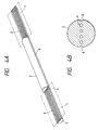
- Opening surfaces 7 in which the introduction grooves 5 are exposed are preferably formed on the same side in the opposite end portions of the connecting member as shown in Fig. 4A. This is a preferred form from the points of view of easiness of formation of the introduction portion 3 on production, easiness of insertion of optical fibers into the through-holes 4 and workability in fixture of connecting.
- positioning grooves 6 are formed, for example, in alignment with the through-holes 4 in the outer surface of the retaining portion 2 so that a connecting apparatus such as a fusion connecting apparatus, or the like, carries out connecting work easily by using the positioning grooves while the connecting member is grasped and fixed in predetermined position as will be described later.
- a small-diameter portion 8 having a diameter smaller than the outer diameter of an optical fiber to be inserted may be formed in the intermediate portion in each of the through-holes 4 of the retaining portion 2 so that an end of each of the optical fibers can be stopped by the small-diameter portion 8 to thereby set the facing position. Because the facing position is set to be nearly constant, evenness of connecting work can be attained. Accordingly, not only variation in connecting loss can be reduced but also reliability upon the formation of connecting can be improved. Although a gap is formed in the facing portion when optical fibers are faced each other through the small-diameter portion 8, the connecting loss can be reduced by pouring matching oil into the gap portion.
- the small-diameter portion 8 can be formed by partially heat-fusing the intermediate portion of the through-hole 4 as shown in Fig. 5A or by drawing the heated portion as shown in Fig. 5B.
- small transparent spherical bodies 9 formed from the same material as that of optical fibers may be put in the intermediate portions of the through-holes 4 as shown in Fig. 6.
- glass balls are used.
- insertion of the glass balls it is possible to consider a method in which glass balls are fixed and held by partial heating as shown in Figs. 5A and 5B after positioning rods are inserted from one insertion side and the glass balls are inserted from the other insertion side.
- Fig. 7 shows the configuration of a connecting member in which a slit 10 reaching the through-holes 4 is formed in the center of the retaining portion 2.
- Various functions can be given to the slit 10.
- the slit 10 as a facing line for optical fibers
- use of the slit 10 as an air escape hole for smooth insertion of optical fibers into the through-holes 4
- use of the slit 10 as a hole for injecting matching oil
- use of the slit 10 as an inlet for injecting an adhesive agent into the through-holes to fix connecting of optical fibers, and the like.
- a transparent plate 11 formed from the same material as that of optical fibers may be inserted into the slit 10 so that the facing portion of optical fibers can be positioned in the same manner as described above with reference to Fig. 5A, 5B or 6. Because merely the slit and the transparent plate are inserted, easy formation can be made compared with the configuration shown in Fig. 5A, 5B or 6.
- a transparent plate coated with an antireflection film may be used as the transparent plate 11 so that reflection in optical connecting is prevented to make it possible to reduce the connecting loss.
- the connecting member for glass optical fibers is preferably formed from silica glass mainly containing SiO 2 which is the same material as that of optical fibers, because the connecting material is integrated with the optical fibers. Further, it is also preferable from the point of view of temperature stability that the connecting member is formed from silica glass having a thermal expansion coefficient substantially equal to that of optical fibers to be connected so that it is possible to avoid a problem of occurrence of disconnecting because of physical distortion caused by a difference in thermal expansion due to a change in temperature in the condition of use.
- Fig. 8 shows the change of thermal expansion coefficient due to additives supplied to silica glass.
- the thermal expansion coefficient of the connecting member is preferably limited to be in a range of ⁇ 0.5 ⁇ 10 -6 of the thermal expansion coefficient of optical fibers.
- the connecting member When the connecting member is heated at the time of connecting of optical fibers while optical fibers are faced each other in the through-holes, the inner diameter of the through-holes is contracted because softening of the connecting member. Accordingly, the axis of optical fibers is automatically aligned to make the formation of optical connecting better.
- the connecting member is formed from silica glass having a softening temperature equal to or preferably slightly lower than that of optical fibers in order to avoid the softening and deformation of optical fibers before the heat-softening of the connecting member.
- the softening point of the glass can be obtained from the relation of temperature and viscosity as shown in Fig.
- the softening point (softening temperature) is defined as a temperature where the viscosity is 10 7.6 .
- the core is silica glass containing 5-6wt% of GeO 2 and the clad is pure silica glass.
- the softening temperature of the typical single-mode optical fiber is 1660-1680°C because it is considered as SiO 2 as shown in Fig. 9B.
- a temperature where the viscosity becomes 10 5 poise is called "flow point”.
- glass process is performed under a temperature higher than softening point (temperature) but lower than flow point (temperature).
- the temperature of the optical fiber becomes lower than the softening point and that of the connecting member becomes higher than flow point. Therefore, the maximum difference between the softening temperatures of the optical fiber and the connecting member is about 250°C according to Fig. 9B.
- the thermal expansion coefficient and softening temperature of the connecting member are set based on comparison with silica glass of a clad portion which is an overwhelming majority compared with a core portion. If glass optical fibers are multi-mode type fibers large in core size or fibers having clads supplied with dopant, the thermal expansion coefficient and softening temperature of the connecting member vary in accordance with the respective composition.
- the softening temperature of the connecting member formed from silica glass can be lowered by addition of a fluorine, a chlorine, a hydroxyl group (OH group) or a titanium dioxide.
- a fluorine a chlorine, a hydroxyl group (OH group) or a titanium dioxide.
- GeO 2 , P 2 O 5 , B 2 O 3 , or the like is a component for lowering the softening temperature of silica glass but composition distortion occurs easily because even addition at the time of the formation of the glass mother material is difficult. Accordingly, a hole-forming process for forming through-holes becomes difficult.
- the softening temperature of silica glass is obtained on the basis of the relation with "temperature-viscosity" characteristic.
- Fig. 9A shows "temperature-viscosity" characteristic of silica glass (SiO 2 ) not containing any of such additives as described above and "temperature-viscosity” characteristic in the cases where 2 wt% of a titanium dioxide, 2 wt% of a chlorine, 2 wt% of a fluorine and 0.5 wt% of a hydroxyl group are added to the silica glass individually, respectively.
- the temperature (softening temperature) of a softening point (softening viscosity) at which softening starts is obtained.
- the viscosity of silica glass can be reduced by increasing the amount of additives as shown in Fig. 9B.
- the lower limit value of the softening temperature of the connecting member is not limited specifically but the softening temperature of the connecting member is preferably selected to be about 1300°C because it is undesirable that a too large difference is created between the glass viscosity of the connecting member and the glass viscosity of glass optical fibers.
- the light refracting index of the silica glass is reduced.
- a connecting member formed from such glass is used, light once radiated to the outside of optical fibers may enter into the optical fibers again from the connecting member to thereby reduce the quality of signal light.
- addition of a chlorine or a hydroxyl group can increase the refracting index of silica glass by a value of from about 0.05 to about 0.1 %. Accordingly, it may be designed so that the optimum value is obtained by using a plurality of additives in combination from these additives.
- the glass optical fiber connecting member is preferably formed from silica glass containing additives singly or in combination as follows: 0.5 wt% or less of a hydroxyl group; 2 wt% or less of a fluorine; 3.5 wt% or less of a chlorine; and 8 wt% or less of a titanium dioxide.
- a glass mother material containing SiO2 as a main component is prepared by one of various methods such as a VAD method, an OVD method, a direct method, a sol-gel method, and so on.
- addition of the additives to silica glass can be made by mixing TiCl 4 in SiCl 4 which is a raw-material gas for flame hydrolysis.
- a composition gas such as SF 6 , CF 4 , SiF 4 , or the like, is used.
- a chlorine a gas such as Cl 2 , CCl 4 , SiCl 4 , or the like, is used.
- the introduction of a hydroxyl group can be made in a range of from 700 to 1000 ppm by generating transparent glass in oxyhydrogen flame in a direct method. Alternatively, there is a method in which a smoked glass body is exposed to an atmosphere containing water vapor when transparent glass is formed from the smoked glass body, or the like.
- the glass mother material is then drawn or ground to form a columnar glass block 40 having a desired diameter as shown in Fig. 10A. Further, a plurality of prepared holes 41 to 44 which become through-holes are provided in the glass block 10 so as to be symmetric with respect to the center of the block. Incidentally, if only one prepared hole is required, the prepared hole may be provided in the center of the block. This prepared hole may be provided by a method of ultrasonic processing, or the like.
- a dummy member for drawing is fusion-welded with one end of the glass block 40.
- the glass block 40 is then heat-drawn to form a glass linear body 46 having a through-hole having a desired inner diameter, the glass linear body 46 is cut into a predetermined length to form a glass rod-shaped body.
- a plurality of prepared holes 41 to 44 are provided in the glass block 40 and an electric resistance heating furnace 50 surrounding the outer circumference of the glass block is used as a heat source which is a heating means for drawing the glass block, the prepared holes 41 and 44 near the outer circumference of the glass block are heated more intensively than the prepared holes 42 and 43 in the inside of the glass block. As a result, the diameter of the prepared holes 41 and 44 is apt to be reduced. Accordingly, the finished inner diameter of the through-holes near the outer circumference of the glass block becomes larger than that of the through-holes near the center of the glass block. Accordingly, the connecting loss slightly varies.
- the inner diameter of the prepared holes 41 and 44 formed in the outer circumferential side of the glass block 40 is formed so as to be larger than the inner diameter of the prepared holes 42 and 43 formed in the inside of the glass block in advance as shown in Fig. 11.
- the drawing-start end of the glass block 40 is preferably processed in the form of a cone 45 in advance in order to perform stable drawing speedily without production of such a large deal of aborting portions.
- the processing may be performed by a method of mechanical grinding or a method in which the drawing end of the glass block may be fused by another heating means, or the like, so as to be drawn in advance.
- the processing of the prepared holes may be carried out before or after the drawing end of the glass bock is shaped like a cone 45 in advance, the reduction of the diameter of the prepared holes near the outer circumference of the glass block can be suppressed more greatly when the processing is carried out after the drawing end is shaped like a cone.
- Figs. 12 and 13 show situations of the change of the inner diameter of through-holes in the case where a glass block having an outer diameter of 50 mm is heat-drawn to obtain a glass linear body having an outer diameter of 1.28 mm.
- Fig. 12 shows the case of heat-drawing the glass block without processing of the drawing-start end of the glass block into the form of a cone.
- a desired inner diameter is obtained in the through-holes 42' and 43' in the inside of the glass block when the glass block is drawn to about 30 m after the start of drawing, whereas a desired inner diameter is not obtained in the through-holes 41' and 44' in the outside of the glass block so that a large deal of wastes are produced because drawing does not reach a stationary state before the glass block is drawn to about 230 m.
- Fig. 13 shows the case where the glass block is heat-drawn in the condition in which the drawing-start end of the glass block is processed to be in the form of a cone with a conical angle of about 60 degrees in advance.
- a desired inner diameter is obtained in the through-holes 42' and 43' in the inside of the glass block in the same manner as in Fig. 12 after the start of drawing, whereas a desired inner diameter is also obtained in the through-holes 41' and 44' in the outside of the glass block when the glass block is drawn to about 80 m. Accordingly, the quantity of wasteful drawing is suppressed.
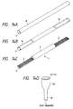
- the glass linear body 46 thus heat-drawn as shown in Fig. 14D is cut into a predetermined length to form a glass rod-shaped body 12 as shown in Figs. 14A to 14C.
- Introduction portions 3 in the opposite end portions of the glass rod-shaped body 12 are formed by cutting or grinding a nearly semicolumnar cut portion 14 so as to cross the respective nearly centers of the through-holes 4.
- a nearly half of each through-hole 4 is removed and the remaining half thereof is left as a semicircular groove communicated with the through-hole 4 of the optical fiber retaining portion 2 in the center portion which is not removed.
- the semicircular grooves are provided at the opposite ends as introduction grooves 5 for guiding insertion of end portions of optical fibers into the through hole 4.
- the glass rod-shaped body 12 which is formed by the heat-drawing shown in Fig. 15D as similar to Fig. 14D, is divided into two parts so as to cross the respective nearly centers of the through-holes 4 to thus form semicolumnar members 13.
- One semicolumnar member 13 obtained by division into two parts is cut into a short length and joined with the center portion of the other semicolumnar member 13 by a suitable means so as to be united into one body.
- connecting member 1 having introduction portions 3 provided in opposite end portions and provided with introduction grooves 5 for guiding insertion of end portions of optical fibers into the through-holes 4 and having an optical fiber retaining portion 2 in the center portion, in the same manner as in Fig. 14C.
- a glass block 40 made of quartz containing 0.6 wt% of a fluorine was formed as the mother material for the connecting member by a VAD method.
- the glass block was processed in the form of a column having an outer diameter of 50 mm and prepared holes 41 to 44 are formed in the arrangement shown in Fig. 11 at hole intervals of 10 mm.
- the diameter of the prepared hole 42 and 43 near the center of the glass block was made 5 mm, and the diameter of the prepared holes 41 and 44 in the outside of the glass block was made 6 mm.
- One end of the glass block 40 up to 50 mm from the end surface of the glass block was processed to be in the form of a cone and drawn by using an electric resistance heating furnace to form a glass linear body having an outer diameter of 1.28 mm.
- the hole interval between the through-holes was 255 ⁇ m; the diameter of the through-holes in the inside of the glass block was 127 ⁇ m; and the diameter of the through-holes in the outside of the glass block was 128 ⁇ m.
- Opposite end portions of this glass rod-shaped body were removed by grinding in a method shown in Figs. 14A to 14C to obtain an optical fiber connecting member according to the present invention.
- Tape-shaped four-core single-mode optical glass fibers were inserted in this optical fiber connecting member so as to be faced each other, and pushing force was applied to the optical fibers which will be described later, and the butt-joint position was heated by using arc discharge to thus form connecting.
- the optical loss due to the connecting was 0.15 dB, and the reflection attenuation quantity was not smaller than 55 dB. It was confirmed that complete light connecting was formed. Further, the quantity of the change of the loss in this connecting product was not larger than 0.02 dB in a temperature range of from -40 to +85°C, so that this connecting product exhibited very good characteristic.
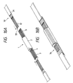
- Figs. 16A and 16B shows that tape-shaped coated optical fiber cable 30 having four coated optical glass fibers 32 arranged in one line are inserted into the connecting member 1.
- a coating 31 at a connecting end portion of the tape-shaped coated optical fiber cable 30 is removed by a predetermined length to expose optical fibers 32, and ends 33 of the optical fibers are cut and planished so as to be arranged in one line.
- the ends 33 of the optical fibers are put into the introduction grooves 5 of the introduction portion 3 on one end of the connecting member 1, while slightly inclined and are forcedly forwarded so as to be slid in the grooves. Then, the ends 33 are inserted into the through-holes 4 of the retaining portion 2 which are formed integrally with the introduction grooves 5.
- the ends 33 of the optical fibers inserted into the through-holes 4 are faced each other at the center of the retaining portion 2, with the respective ends of optical fibers inserted into the through-holes 4 in the same manner as described above from the other end side of the connecting member 1. Further, if positioning members for facing of optical fibers are provided in the through-holes 4, the ends 33 of the optical fibers attach on the members so as to automatically stop the insertion.
- the connecting member 1 After the optical fibers 32 are inserted into the connecting member 1 from its opposite sides, the connecting member 1 is heated in the vicinity of the facing of the optical fibers by discharge electrodes of an arc discharge as shown in Fig. 17. The connecting member is once expanded in the heating process by this heating, however thereafter, the inner diameter of the through-holes 4 is contracted when the temperature approaches the softening temperature. Accordingly, the axis alignment of the optical fibers inserted in the through-holes is performed automatically so as to obtain a good optical connecting condition. Further, in this occasion, the inner walls of the through-holes 4 are partially fused with the optical fibers so that connecting is fixed.
- the respective end portions 33 of the optical fibers inserted in the opposite directions are fused with each other so that fusion connecting can be formed before the connecting member is fused with the optical fibers.
- This is considered to be caused by a difference in heat capacity between the connecting member and the optical fibers because not only the optical fibers are floated up in the through-holes but also the volume of the optical fibers is so small that the ratio of the volume of the optical fibers to the volume of the connecting member is one to several tens.
- the discharge electrodes are used as a heating means in this embodiment because arc discharge heating is effective from the point of view that in that control on the quantity of heating and setting of the heating position can be made accurately, any other heating means such as resistance heating, dielectric heating, torch, or the like, may be used.
- the inner diameter of the through-holes 4 in the optical fiber connecting member according to the present invention is formed with very good accuracy (from +0.5 to 2 ⁇ m) compared with the outer diameter of the optical fibers 32, the aforementioned heating is not always required and fixture may be made by means of an adhesive agent 34.
- the aforementioned adhesive agent 34 may be used additionally in order to make the connecting more securely.
- the optical fibers may be inserted into the connecting member after an adhesive agent is applied in advance onto the rear portions of the optical fibers except portions near the ends of the optical fibers, or an adhesive agent relatively low in viscosity may be poured into the through-holes after the optical fibers are inserted into the connecting member so as to be connected to each other.
- the ends 33 of the optical fibers may be preferably inserted into the connecting member in the condition in which matching oil is given to the ends 33 of the optical fibers, or the through-holes may be filled with matching oil in advance.
- the discharge electrodes for the arc discharge can be used a fusion connecting apparatus as used in fusion connecting as shown in Fig. 18.
- the fusion connecting apparatus need not be so accurate as to have axis alignment functions compared with the fusion connecting apparatus which is used generally. That is, a low-cost simple fusion connecting apparatus suffices for the purpose.
- This fusion connecting apparatus has a grasping mechanism 26 composed of tables 24 for putting the connecting member 1 thereon and fixture blocks 23, discharge electrodes 17 for generating arc discharge, and an illumination device 27.
- the connecting member 1 is positioned by and mounted on V-grooves 25 formed in the tables 24 and grasped and fixed by the fixture blocks 23.
- the optical fibers may be inserted into the connecting member 1 before or after the connecting member 1 is mounted on the apparatus. Then the facing state of the optical fibers is confirmed by using the illumination device 27 and an observation mechanism not shown, the positions of the discharge electrodes 17 are set, and then the connecting member is heated by arc discharge.
- two pairs of discharge electrodes 17 may be provided so that the opposite sides of the facing portion of the optical fibers are heated separately.
- the connecting portion is reinforced by a reinforcing member 22 as shown in Figs. 19A and 19B.
- the reinforcing member 22 is composed of a hot-melt member 19 such as a tube, or the like, an aggregate 20 made of a rigid rod, and a heat-shrinkable tube 21 for housing these parts.
- the hot-melt member 19 such as a tube and the heat-shrinkable tube 21 are made to pass onto the optical fiber cable 30 before the optical fibers are connected, so that the hot-melt member 19 and the heat-shrinkable tube 21 are moved on the connecting member 1 after the optical fibers are connected.
- the hot-melt member 19 is melted by heating so that not only the connecting member 1 and the aggregate 20 are united into one body but also the heat-shrinkable tube 21 is shrunk by heating to thereby reinforce the connecting portion.
- the aforementioned configuration concerning the introduction grooves 5 of the optical fiber connecting member can be applied to the configuration in which optical fibers are inserted and fixed into a detachable type optical connecter capable of disconnecting the optical fibers.
- introduction grooves are formed in opposite sides of the retaining portion integrally with through-holes. Accordingly, by pushing optical fibers along the introduction grooves, ends of the optical fibers can be inserted into the through-holes easily. The workability is improved extremely, so that the time required for connecting can be shortened.
- the through-holes can be formed accurately and easily merely by heat-drawing a columnar glass block having prepared holes formed therein and cutting the columnar glass block into a predetermined length.
- the introduction grooves can be formed integrally with the through-holes easily by merely grinding or polishing the glass block.
- optical fiber connecting member in the optical fiber connecting member according to the present invention, fixture of connecting due to fusion is performed without the necessity of axis alignment of the optical fibers by carrying out heating by means of arc discharge, or the like, for connecting. Accordingly, high-reliable connecting can be formed.
Landscapes
- Physics & Mathematics (AREA)
- Engineering & Computer Science (AREA)
- Plasma & Fusion (AREA)
- General Physics & Mathematics (AREA)
- Optics & Photonics (AREA)
- Chemical & Material Sciences (AREA)
- General Life Sciences & Earth Sciences (AREA)
- Geochemistry & Mineralogy (AREA)
- Manufacturing & Machinery (AREA)
- Life Sciences & Earth Sciences (AREA)
- Materials Engineering (AREA)
- Organic Chemistry (AREA)
- Mechanical Coupling Of Light Guides (AREA)
Applications Claiming Priority (6)
| Application Number | Priority Date | Filing Date | Title |
|---|---|---|---|
| JP15944595 | 1995-06-26 | ||
| JP159445/95 | 1995-06-26 | ||
| JP254794/95 | 1995-10-02 | ||
| JP25479495 | 1995-10-02 | ||
| JP64121/96 | 1996-03-21 | ||
| JP06412196A JP3362329B2 (ja) | 1995-06-26 | 1996-03-21 | 光ファイバ接続部材とその製造方法及び接続方法 |
Publications (1)
| Publication Number | Publication Date |
|---|---|
| EP0751411A1 true EP0751411A1 (de) | 1997-01-02 |
Family
ID=27298394
Family Applications (1)
| Application Number | Title | Priority Date | Filing Date |
|---|---|---|---|
| EP96109992A Withdrawn EP0751411A1 (de) | 1995-06-26 | 1996-06-20 | Koppelröhrchen für optische Fasern, Methode zu seiner Herstellung und Methode zur Verbindung optischer Fasern |
Country Status (5)
| Country | Link |
|---|---|
| US (2) | US5710850A (de) |
| EP (1) | EP0751411A1 (de) |
| JP (1) | JP3362329B2 (de) |
| AU (1) | AU705171B2 (de) |
| CA (1) | CA2179565A1 (de) |
Cited By (1)
| Publication number | Priority date | Publication date | Assignee | Title |
|---|---|---|---|---|
| WO2008076786A1 (en) * | 2006-12-18 | 2008-06-26 | Lockheed Martin Corporation | Method and apparatus for splicing fiber optic cable |
Families Citing this family (29)
| Publication number | Priority date | Publication date | Assignee | Title |
|---|---|---|---|---|
| JP3362329B2 (ja) * | 1995-06-26 | 2003-01-07 | 住友電気工業株式会社 | 光ファイバ接続部材とその製造方法及び接続方法 |
| US6138476A (en) * | 1995-06-26 | 2000-10-31 | Sumitomo Electric Industries, Ltd. | Method of producing an optical fiber coupling member |
| US6231243B1 (en) * | 1997-08-29 | 2001-05-15 | Hoya Corporation | Preform and process for the production thereof |
| EP1006355A3 (de) * | 1998-11-30 | 2000-11-08 | The Institute of Physical and Chemical Research | Kapillarelektrophoresegerät |
| US6099170A (en) * | 1999-01-07 | 2000-08-08 | Thomas & Betters International, Inc. | Splice protection sleeve for a plurality of optical fibers and method of installation |
| JP3710083B2 (ja) * | 1999-03-17 | 2005-10-26 | 日本板硝子株式会社 | 光ファイバ接続用ガラス部品の製造方法 |
| US6427491B1 (en) * | 1999-08-20 | 2002-08-06 | Corning Incorporated | Method for making fibers having cores with non-circular cross-sections |
| AU754530B2 (en) * | 1999-11-04 | 2002-11-21 | Sumitomo Electric Industries, Ltd. | Optical transmission line |
| US6826650B1 (en) * | 2000-08-22 | 2004-11-30 | Qlogic Corporation | Disk controller configured to perform out of order execution of write operations |
| US6568074B1 (en) * | 2000-09-15 | 2003-05-27 | Fitel Usa Corp. | Method for making planar optical fiber circuits |
| JP2002214466A (ja) * | 2001-01-23 | 2002-07-31 | Sumitomo Electric Ind Ltd | 光ファイバ |
| US7467528B2 (en) * | 2001-10-18 | 2008-12-23 | Research Institute Of Industrial Science & Technology | Method of fabricating dual hole glass ferrules |
| US20040194511A1 (en) * | 2002-02-01 | 2004-10-07 | Chih-Hsing Cheng | Sol-gel-derived halogen-doped glass |
| US20030147606A1 (en) * | 2002-02-01 | 2003-08-07 | Shiho Wang | Sol-gel-based optical preforms and methods of manufacture |
| JP3801933B2 (ja) * | 2002-03-15 | 2006-07-26 | 湖北工業株式会社 | 光学部材の製造方法 |
| US20040050110A1 (en) * | 2002-08-29 | 2004-03-18 | Berkey George E. | Methods for fabricating optical fibers and optical fiber preforms |
| JP2005025135A (ja) * | 2003-07-04 | 2005-01-27 | Showa Electric Wire & Cable Co Ltd | 高信頼性光導波路型デバイス |
| US20060115217A1 (en) * | 2004-11-29 | 2006-06-01 | Us Conec, Ltd. | Multi-fiber ferrule and a mold therefor |
| US20090252468A1 (en) * | 2005-04-26 | 2009-10-08 | The Furukawa Electric Co, Ltd. | Optical fiber preform including a non-axisymmetric cross section |
| JP2008277582A (ja) * | 2007-04-27 | 2008-11-13 | Fujikura Ltd | 光ポンピングデバイス用マルチコアファイバとその製造方法、光ポンピングデバイス、ファイバレーザ及びファイバ増幅器 |
| US7903912B2 (en) * | 2008-03-10 | 2011-03-08 | Hitachi Cable, Ltd. | Optical connector |
| JP4968123B2 (ja) * | 2008-03-10 | 2012-07-04 | 日立電線株式会社 | 光コネクタ |
| NL2004199C2 (nl) * | 2010-02-05 | 2011-08-08 | Stichting Noble House | Voertuig voorzien van een inrichting voor het detecteren van externe lasermeetapparatuur en werkwijze voor het aanbrengen van een dergelijke inrichting. |
| JP5700699B2 (ja) * | 2012-05-11 | 2015-04-15 | 株式会社フジクラ | 広帯域低損失光ファイバの製造方法 |
| JP6048031B2 (ja) * | 2012-09-24 | 2016-12-21 | 住友電気工業株式会社 | 光ファイバ製造方法 |
| US11733459B2 (en) * | 2018-12-31 | 2023-08-22 | Sterlite Technologies Limited | Method for modification of surface of optical fiber preform |
| EP3923049B1 (de) * | 2019-02-05 | 2026-01-14 | Sumitomo Electric Optifrontier Co., Ltd. | Schmelzspleissvorrichtung und schmelzspleissverfahren |
| JP7223382B1 (ja) * | 2022-02-10 | 2023-02-16 | フォトニックサイエンステクノロジ株式会社 | ピッチ変換器製造装置 |
| WO2025150374A1 (ja) * | 2024-01-09 | 2025-07-17 | 住友電気工業株式会社 | 保持部材、光ファイバ接続部品、光コネクタ、接続アセンブリ、および光ファイバ接続部品の製造方法 |
Citations (8)
| Publication number | Priority date | Publication date | Assignee | Title |
|---|---|---|---|---|
| EP0001278A1 (de) * | 1977-09-23 | 1979-04-04 | LES CABLES DE LYON Société anonyme dite: | Verbindungsverfahren und -Vorrichtung für optische Fasern |
| GB2022859A (en) * | 1978-06-12 | 1979-12-19 | Thomas & Betts Corp | Fibre Optic Splice |
| EP0098548A2 (de) * | 1982-07-09 | 1984-01-18 | KRONE GmbH | Einrichtung und Verfahren zur Herstellung einer mechanischen, nicht lösbaren Spleissverbindung zweier Lichtwellenleiter aus Quarzglas |
| JPS59228214A (ja) * | 1983-06-09 | 1984-12-21 | Furukawa Electric Co Ltd:The | 多芯光フアイバ心線の接続方法 |
| EP0241724A2 (de) * | 1986-03-14 | 1987-10-21 | Sumitomo Electric Industries Limited | Optischer Stecker und Spleiss |
| EP0408926A1 (de) * | 1989-06-26 | 1991-01-23 | Alcatel Fibres Optiques | Verfahren zur Herstellung von Kapillarröhren und Anwendung als Kupplung für Lichtwellenleiter |
| EP0484850A1 (de) * | 1990-11-08 | 1992-05-13 | Alcatel Fibres Optiques | Herstellungsverfahren von Multisteckerstiften mit einer Reihe von Kanälen mit parallelen Achsen und so hergestellter Multisteckerstift |
| EP0652184A1 (de) * | 1993-11-08 | 1995-05-10 | Alcatel Cable Interface | Verfahren zum Herstellen einer Vorform für Multisteckerstifte aus Quarz und die so erhaltende Vorform |
Family Cites Families (7)
| Publication number | Priority date | Publication date | Assignee | Title |
|---|---|---|---|---|
| JPH0669850B2 (ja) * | 1982-07-26 | 1994-09-07 | 三田工業株式会社 | 物品の組立ラインに於ける搬送システム |
| JPS6125109A (ja) * | 1984-07-13 | 1986-02-04 | Sumitomo Electric Ind Ltd | 光フアイバ接続用結合部材 |
| JPH02103004A (ja) * | 1988-10-12 | 1990-04-16 | Fujikura Ltd | 光ファイバの接続方法 |
| JP2612934B2 (ja) * | 1989-04-22 | 1997-05-21 | 住友電気工業株式会社 | 光ファイバの融着接続装置 |
| AU649162B2 (en) * | 1991-08-17 | 1994-05-12 | Nippon Telegraph & Telephone Corporation | Optical connector |
| US5602951A (en) * | 1994-04-14 | 1997-02-11 | Sumitomo Electric Industries, Ltd. | Ferrule for optical connector and process for making same |
| JP3362329B2 (ja) * | 1995-06-26 | 2003-01-07 | 住友電気工業株式会社 | 光ファイバ接続部材とその製造方法及び接続方法 |
-
1996
- 1996-03-21 JP JP06412196A patent/JP3362329B2/ja not_active Expired - Fee Related
- 1996-06-20 EP EP96109992A patent/EP0751411A1/de not_active Withdrawn
- 1996-06-20 CA CA002179565A patent/CA2179565A1/en not_active Abandoned
- 1996-06-21 US US08/670,760 patent/US5710850A/en not_active Expired - Fee Related
- 1996-06-25 AU AU56183/96A patent/AU705171B2/en not_active Ceased
-
1997
- 1997-09-30 US US08/941,548 patent/US5891210A/en not_active Expired - Fee Related
Patent Citations (8)
| Publication number | Priority date | Publication date | Assignee | Title |
|---|---|---|---|---|
| EP0001278A1 (de) * | 1977-09-23 | 1979-04-04 | LES CABLES DE LYON Société anonyme dite: | Verbindungsverfahren und -Vorrichtung für optische Fasern |
| GB2022859A (en) * | 1978-06-12 | 1979-12-19 | Thomas & Betts Corp | Fibre Optic Splice |
| EP0098548A2 (de) * | 1982-07-09 | 1984-01-18 | KRONE GmbH | Einrichtung und Verfahren zur Herstellung einer mechanischen, nicht lösbaren Spleissverbindung zweier Lichtwellenleiter aus Quarzglas |
| JPS59228214A (ja) * | 1983-06-09 | 1984-12-21 | Furukawa Electric Co Ltd:The | 多芯光フアイバ心線の接続方法 |
| EP0241724A2 (de) * | 1986-03-14 | 1987-10-21 | Sumitomo Electric Industries Limited | Optischer Stecker und Spleiss |
| EP0408926A1 (de) * | 1989-06-26 | 1991-01-23 | Alcatel Fibres Optiques | Verfahren zur Herstellung von Kapillarröhren und Anwendung als Kupplung für Lichtwellenleiter |
| EP0484850A1 (de) * | 1990-11-08 | 1992-05-13 | Alcatel Fibres Optiques | Herstellungsverfahren von Multisteckerstiften mit einer Reihe von Kanälen mit parallelen Achsen und so hergestellter Multisteckerstift |
| EP0652184A1 (de) * | 1993-11-08 | 1995-05-10 | Alcatel Cable Interface | Verfahren zum Herstellen einer Vorform für Multisteckerstifte aus Quarz und die so erhaltende Vorform |
Non-Patent Citations (1)
| Title |
|---|
| PATENT ABSTRACTS OF JAPAN vol. 9, no. 105 (P - 354) 9 May 1985 (1985-05-09) * |
Cited By (1)
| Publication number | Priority date | Publication date | Assignee | Title |
|---|---|---|---|---|
| WO2008076786A1 (en) * | 2006-12-18 | 2008-06-26 | Lockheed Martin Corporation | Method and apparatus for splicing fiber optic cable |
Also Published As
| Publication number | Publication date |
|---|---|
| US5710850A (en) | 1998-01-20 |
| AU5618396A (en) | 1997-01-09 |
| US5891210A (en) | 1999-04-06 |
| JP3362329B2 (ja) | 2003-01-07 |
| JPH09159859A (ja) | 1997-06-20 |
| AU705171B2 (en) | 1999-05-20 |
| CA2179565A1 (en) | 1996-12-27 |
Similar Documents
| Publication | Publication Date | Title |
|---|---|---|
| US5710850A (en) | Optical fiber coupling member, method of producing the same and method of connecting optical fibers | |
| EP0423999B1 (de) | Verfahren zum Aufweiten von Bohrungsendbereichen von Kapillarröhrchen | |
| EP0213856B1 (de) | Verbindungsverfahren für einen optischen Faser mit einem optischen Bauteil | |
| AU615336B2 (en) | Method of making fiber coupler having integral precision connection wells | |
| US4948217A (en) | Optic coupler | |
| CA1267803A (en) | Fiber optic coupler and method | |
| EP0409447B1 (de) | Methode zur Herstellung eines Lichtwellenleiter-Kopplers | |
| US5339372A (en) | Low loss coupler | |
| EP0436182A2 (de) | Faseroptischer 1xN-Koppler und Herstellungsverfahren | |
| US4647150A (en) | Mechanical splice for optical fibers | |
| CA2032876C (en) | Fused fiber optic coupler | |
| US4822389A (en) | Capillary splice method | |
| US6810691B2 (en) | Method for making glass tubing with multiple bores | |
| US4917718A (en) | Method of making capillary tube | |
| US6138476A (en) | Method of producing an optical fiber coupling member | |
| GB1599885A (en) | Optical fibre terminations | |
| AU726068B2 (en) | Optical fiber coupling member, method of producing the same and method of connecting optical fibers | |
| US4960316A (en) | Capillary splice | |
| EP4571376A1 (de) | Mehradrige faseroptische ein-/ausfächerungsvorrichtung | |
| CA1326370C (en) | Capillary splice and method | |
| JPH1164671A (ja) | ガラス毛細管 | |
| JPH04268507A (ja) | 光ファイバの接合が容易な光通信用部品 | |
| HK22097A (en) | Method of making fiber optic couplers | |
| JPS6299703A (ja) | 光フアイバの接続方法 |
Legal Events
| Date | Code | Title | Description |
|---|---|---|---|
| PUAI | Public reference made under article 153(3) epc to a published international application that has entered the european phase |
Free format text: ORIGINAL CODE: 0009012 |
|
| AK | Designated contracting states |
Kind code of ref document: A1 Designated state(s): DE GB SE |
|
| 17P | Request for examination filed |
Effective date: 19970218 |
|
| 17Q | First examination report despatched |
Effective date: 20020606 |
|
| STAA | Information on the status of an ep patent application or granted ep patent |
Free format text: STATUS: THE APPLICATION IS DEEMED TO BE WITHDRAWN |
|
| 18D | Application deemed to be withdrawn |
Effective date: 20041021 |