EP0751414A2 - Varioobjektiv - Google Patents
Varioobjektiv Download PDFInfo
- Publication number
- EP0751414A2 EP0751414A2 EP96110388A EP96110388A EP0751414A2 EP 0751414 A2 EP0751414 A2 EP 0751414A2 EP 96110388 A EP96110388 A EP 96110388A EP 96110388 A EP96110388 A EP 96110388A EP 0751414 A2 EP0751414 A2 EP 0751414A2
- Authority
- EP
- European Patent Office
- Prior art keywords
- lens
- unit
- refractive power
- sub
- denoted
- Prior art date
- Legal status (The legal status is an assumption and is not a legal conclusion. Google has not performed a legal analysis and makes no representation as to the accuracy of the status listed.)
- Granted
Links
Images




Classifications
-
- G—PHYSICS
- G02—OPTICS
- G02B—OPTICAL ELEMENTS, SYSTEMS OR APPARATUS
- G02B15/00—Optical objectives with means for varying the magnification
- G02B15/14—Optical objectives with means for varying the magnification by axial movement of one or more lenses or groups of lenses relative to the image plane for continuously varying the equivalent focal length of the objective
- G02B15/144—Optical objectives with means for varying the magnification by axial movement of one or more lenses or groups of lenses relative to the image plane for continuously varying the equivalent focal length of the objective having four groups only
- G02B15/1441—Optical objectives with means for varying the magnification by axial movement of one or more lenses or groups of lenses relative to the image plane for continuously varying the equivalent focal length of the objective having four groups only the first group being positive
- G02B15/144113—Optical objectives with means for varying the magnification by axial movement of one or more lenses or groups of lenses relative to the image plane for continuously varying the equivalent focal length of the objective having four groups only the first group being positive arranged +-++
Definitions
- This invention relates to zoom lenses suited to be used in television cameras, video cameras, photographic cameras, or the like and, more particularly, to a large relative aperture, high range zoom lens having a relative aperture of 1.64 in F-number at the wide-angle end and a zoom ratio of 8 to 15 and having its front or first lens unit constructed with a plurality of lens sub-units, one lens sub-unit of which is made movable for focusing, or employing the so-called inner focusing method, to shorten the minimum object distance.
- the focusing method of moving a lens unit disposed in front of the lens unit for varying magnification is superior to the others in view of the zoom lens configuration. Since this method permits zooming and focusing to be performed independently of each other, it is possible to assure simplification of the structure of construction of the operating mechanism. Another surpassing merits are that the image sharpness is not affected by zooming and that, for an equivalent object distance, the focusing movement remains constant regardless of any zooming position whatever.
- a zoom lens comprising, in order from an object side, a first lens unit of positive refractive power for focusing (focusing lens unit), a second lens unit of negative refractive power for varying magnification (variator lens unit), a third lens unit of positive or negative refractive power for compensating for the shift of an image plane caused by the variation of magnification (compensator lens unit), an aperture stop and a fourth lens unit of positive refractive power for forming an inage (relay lens unit), totaling four lens units, that is, the so-called 4-unit zoom lens, wherein a lens sub-unit which is a part of the first lens unit is made movable for focusing.
- a zoom lens employing such a so-called "inner" focus type has previously been proposed in, for example, Japanese Patent Publication No. Sho 59-4686.
- the first lens unit is constructed with three lens sub-units, of which the first lens sub-unit is of negative refractive power, the second lens sub-unit is of positive refractive power and the third lens sub-unit is of positive refractive power. Focusing is effected from an infinitely distant object down to an object at a minimum distance, by axially moving the second lens sub-unit toward the image side.
- Japanese Laid-Open Patent Applications Nos. Sho 52-109952, Sho 55-57815 and Sho 55-117119 and Japanese Patent Publications Nos. Sho 61-53696 and Sho 52-41068, etc. also disclose 4-unit zoom lenses, wherein the first lens unit is divided into a plurality of lens sub-units, of which a lens sub-unit nearest to the object side is made stationary during focusing, while one of the subsequent lens sub-units near to the image side is made movable for focusing, employing the inner focusing method.
- the first lens unit is divided into two lens sub-units, wherein the separation between the two lens sub-units increases when focusing is effected from an infinitely distant object to an object at a finite distance.
- the inner focus type of zoom lens as compared with another zoom lens in which the entirety of the first lens unit is moved for focusing, enjoys unique advantages that the effective diameter of the first lens unit becomes smaller, thereby facilitating improvements of the compact form of the whole of the lens system, also that close-up photography, particularly supershort focusing, becomes easy to do, and further that, since the focusing lens sub-unit is relatively small in size and light in weight, so much smaller a driving force suffices, making it possible to ensure rapid focus adjustment.
- the zoom lens For the zoom lens to increase its relative aperture (to, for example, 1.64 in F-number) and its variable magnification ratio (to, for example, 8 or higher,) while still obtaining a good stability of high optical performance throughout the entire variable magnification range and throughout the entire focusing range, it is necessary to set forth appropriate rules of design for the refractive powers of all the lens units, the form and the construction and arrangement of the constituent lenses, and the contribution of each lens unit to achromatism.
- Fig. 13 is a diagram for explaining the thin lens system in the paraxial zone when the first lens unit L1 is constructed with a first lens sub-unit L11 of negative refractive power, a second lens sub-unit L12 of positive refractive power and a third lens sub-unit L13 of positive refractive power.
- Fig. 13 the upper half relative to an optical axis shows a focusing position with an object at infinity, and the lower half relative to the optical axis shows a focusing position with an object at the minimum distance.
- a ray of light is selected based on the found value of the F-number for each focusing position in the telephoto end.
- the height of incidence of the ray on the first lens sub-unit L11 becomes lower when focusing is effected on the closest object than when on the object at infinity.
- the second lens sub-unit L12 the height of incidence of the ray becomes higher.
- the first lens sub-unit L11 as a whole is negative in refractive power and also because the second lens sub-unit L12 is of positive refractive power, it results that, for the closest object, the chromatic aberrations are corrected negative as compared with those for the infinitely distant object.
- the space that admits of the range of axial movement of the second lens sub-unit L12 has to be taken larger, or both of the first and second lens sub-units L11 and L12 have to be strengthened in refractive power to increase the efficiency of focusing.
- the heights of incidence of that ray which is selected based on the F-number on the first and second lens sub-units are caused to vary to a larger extent and, therefore, the variation of the longitudinal chromatic aberration, too, becomes larger.
- the first lens sub-unit must take a more front position.
- the effective diameter of the first lens sub-unit for the wide-angle end has to increase, causing its weight to increase too much.
- the angle of divergence of that ray which is based on the F-number at the telephoto end from the first lens sub-unit is caused to increase.
- the heights of incidence of the ray on the first and second lens sub-units vary to either an equal or larger extent.
- the varied amount of aberrations with variation of the height of incidence of the ray increases with an increase of the refractive powers of the first and second lens sub-units. As a result, the variation of longitudinal chromatic aberration becomes larger.
- the present invention is applied to a 4-unit zoom lens whose first lens unit for focusing is constructed with a front lens sub-unit, an intermediate lens sub-unit and a rear lens sub-unit. Of these lens sub-units, the intermediate lens sub-unit is made axially movable for focusing.
- the present invention sets forth appropriate rules of design for the constituent lenses of each lens sub-unit to reduce the range of variation of spherical aberration, chromatic aberrations and others with zooming and focusing. It is, therefore, an object of the present invention to provide a large relative aperture, high range zoom lens having a good stability of optical performance maintained at a high level throughout the entire variable magnification range and throughout the entire focusing range.
- a zoom lens according to the present invention comprises, in order from an object side to an image side, a first lens unit of positive refractive power which is stationary during zooming, a second lens unit of negative refractive power which is axially movable during zooming, a third lens unit which is axially movable during zooming, and a fourth lens unit of positive refractive power which is stationary during zooming, wherein the first lens unit comprises a front lens sub-unit including at least one positive lens and having a negative refractive power as a whole, an intermediate lens sub-unit including at least one positive lens and a cemented lens and having a positive refractive power as a whole, and a rear lens sub-unit including a cemented lens and having a positive refractive power as a whole, and wherein the intermediate lens sub-unit is moved toward the image side to effect focusing from an infinitely distant object to an object at a minimum object distance.
- L1 denotes the first lens unit
- L2 denotes the second lens unit
- L3 denotes the third lens unit
- L11 denotes the front lens sub-unit
- L12 denotes the intermediate lens sub-unit
- L13 denotes the rear lens sub-unit.
- SP stands for the stop
- P stands for the glass block.
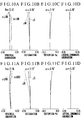
- e-LINE stands for the spectral e-line
- g-LINE stands for the spectral g-line
- ⁇ M stands for the meridional image plane
- ⁇ S stands for the sagittal image plane.
- Figs. 1, 2 and 3 in block diagrams show numerical examples 1, 2 and 3 of zoom lenses of the invention in the wide-angle end, respectively.
- reference character L1 denotes a first lens unit, called the "focusing" (or “front”) lens unit, of positive refractive power which remains stationary during zooming.
- the first lens unit L1 is constructed with a front lens sub-unit L11 including at least one positive lens and having a negative refractive power as a whole, an intermediate lens sub-unit L12 including at least one positive lens and a cemented lens and having a positive refractive power as a whole, and a rear lens sub-unit L13 including a cemented lens and having a positive refractive power as a whole. Focusing from an infinitely distant object to an object at the minimum distance is effected, in Fig. 1, by moving the intermediate lens sub-unit L12 as a whole toward the image side.
- the intermediate lens sub-unit L12 is divided into two parts, of which the front part L12p comprises one or two positive lenses and the rear part L12a comprises a cemented lens, and the front part L12p and the rear part L12a are moved by respective different distances toward the image side. That is, the floating technique is utilized.
- Reference character L2 denotes a second lens unit for varying magnification, called the "variator" lens unit, of negative refractive power. Zooming from the wide-angle end to the telephoto end is effected by axially moving the second lens unit L2 toward the image side monotonously. Note that the second lens unit L2, during zooming, varies the image magnification within a range including unity magnification (-1x).
- Reference character L3 denotes a third lens unit, called the "compensator" lens unit, of positive or negative refractive power. To compensate for the image shift with zooming, it is in the case of the negative refractive power that the third lens unit L3 moves while depicting a locus convex toward the object side. In the case of the positive refractive power, the third lens unit L3 moves toward the object side monotonously. SP stands for a stop.
- Reference character L4 denotes a fourth lens unit, called the "relay lens” unit, of positive refractive power.
- P stands for a color separation prism, optical filters and others which are shown as a glass block in the same figures.
- the 4-unit type of zoom lens is combined with the so-called front focusing method in which the frontmost or first lens unit as a whole is moved for focusing.
- the front focusing method has an advantage that the lens mounting mechanism is simple in structure, because the focusing movement of the first lens unit is constant at every focal length for an equivalent object distance.
- the optical performance especially in respect to spherical aberration and longitudinal chromatic aberration, is varied to a large extent. This is not favorable for shortening the minimum object distance. Moreover, it becomes difficult to correct the image aberrations well throughout the entire area of the image frame.
- the focusing range is extended toward shorter object distances.
- the "inner" focusing method is employed, in which, in a numerical example 1 shown in Fig. 1, the intermediate lens sub-unit L12 included in the first lens unit L1 is moved toward the image side for focusing from an infinitely distant object to an object at the minimum distance, thus assuring maintenance of a good stability of optical performance.
- the intermediate lens sub-unit L12 included in the first lens unit L1 is divided into two parts L12p and L12a, as described above.
- the two parts L12p and L12a are then made to move by respective different distances.
- any one of the air spaces in the lens sub-unit which moves for focusing is made to increase or decrease as the object distance varies. Since this floating causes a change of the slopes and heights of the rays passing through the refracting surfaces, the variation of aberrations is corrected well.
- the floating method which satisfies the condition (10)
- the variation of aberrations, mainly distortion, with focusing is remarkably lessened in the wide-angle region.
- Fig. 14 shows a pair of rays which go to the corners of the image frame in the wide-angle end with an infinitely distant object and an object at the minimum distance under the condition that the positive single lens and the cemented lens are unified to form the intermediate lens sub-unit.
- the upper half relative to an optical axis is shown as focused on the infinitely distance object, and the lower half relative to the optical axis is shown as focused on the object at the minimum distance.
- the ray from an extraaxial object point has a large angle of inclination in the space between the front lens sub-unit and rear lens sub-unit, and is incident on the rear lens sub-unit at a low height. Therefore, the height at which the ray passes through the intermediate lens sub-unit changes largely between when focused on the infinitely distant object and when on the object at the minimum distance. This is the cause of bringing forth the variation of distortion with focusing.
- the cemented surface of large refractive power in the intermediate lens sub-unit has an effect of getting distortion to minus. As focusing goes on from an infinitely distant object for which the height of incidence is high to an object at the minimum distance for which the height of incidence is low, the distortion changes to plus side greatly.
- the angle of inclination of the extraaxial ray decreases to decrease the difference between the heights of incidence of the ray on the front lens sub-unit and the rear lens sub-unit. Therefore, the variation of distortion with focusing becomes very small.
- the floating method that satisfies the condition (10) is employed to reduce the range of variation of distortion for the wide-angle region with focusing.
- most of the focusing function is performed by the lens L12p, while the cemented lens L12a moves a little toward the image side.
- the locus of motion for the cemented lens L12a may be either linear as its speed is constant relative to that of movement of the lens L12p, or non-linear as its speed is accelerated or decelerated.
- Ri is the radius of curvature of the i-th lens surface, when counted from the object side
- Di is the i-th axial thickness or air separation, when counted from the object side
- Ni and ⁇ i are respectively the refractive index for the spectral e-line and the Abbe number of the glass of the i-th lens element, when counted from the object side.
- the intermediate lens sub-unit L12 for focusing comprises a positive lens and a cemented lens composed of positive and negative lenses, to correct the variation of aberrations with focusing. Particularly for the telephoto side, the variation of longitudinal chromatic aberration is corrected well.
- the intermediate lens sub-unit L12 for focusing is divided into two parts, i.e., a positive lens L12p and a cemented lens L12a. Both lenses L12p and L12a are made to move by respective different distances for focusing, that is, the floating method is employed, to correct well the variation of mainly distortion with focusing.
- the intermediate lens sub-unit L12 comprises a lens L12p composed of two positive lenses and a cemented lens L12a, totaling four lens elements, and, further, the floating method is used to correct well the spherical aberration and longitudinal chromatic aberration for the telephoto end.
- Variable Separations Focal Length [mm] 6.70 13.19 26.63 48.95 99.83 D20 0.72 28.72 48.72 60.72 70.38 D27 110.03 76.03 47.76 26.38 2.17 D34 2.05 8.05 16.32 25.70 40.25
- the first lens unit for focusing is constructed with three lens sub-units, i.e., a front lens sub-unit, an intermediate lens sub-unit and a rear lens sub-unit.
- the intermediate lens sub-unit is made axially movable for focusing.
- a zoom lens comprises, in order from an object side to an image side, a first lens unit of positive refractive power which is stationary during zooming, a second lens unit of negative refractive power which is axially movable during zooming, a third lens unit which is axially movable during zooming, and a fourth lens unit of positive refractive power which is stationary during zooming, wherein the first lens unit comprises a front lens sub-unit including at least one positive lens and having a negative refractive power as a whole, an intermediate lens sub-unit including at least one positive lens and a cemented lens and having a positive refractive power as a whole, and a rear lens sub-unit including a cemented lens and having a positive refractive power as a whole, and wherein the intermediate lens sub-unit is moved toward the image side to effect focusing from an infinitely distant object to an object at a minimum object distance.
Landscapes
- Physics & Mathematics (AREA)
- General Physics & Mathematics (AREA)
- Optics & Photonics (AREA)
- Lenses (AREA)
Applications Claiming Priority (3)
| Application Number | Priority Date | Filing Date | Title |
|---|---|---|---|
| JP188671/95 | 1995-06-29 | ||
| JP18867195 | 1995-06-29 | ||
| JP18867195A JP3376177B2 (ja) | 1995-06-29 | 1995-06-29 | ズームレンズ |
Publications (3)
| Publication Number | Publication Date |
|---|---|
| EP0751414A2 true EP0751414A2 (de) | 1997-01-02 |
| EP0751414A3 EP0751414A3 (de) | 1997-12-17 |
| EP0751414B1 EP0751414B1 (de) | 2003-04-09 |
Family
ID=16227821
Family Applications (1)
| Application Number | Title | Priority Date | Filing Date |
|---|---|---|---|
| EP96110388A Expired - Lifetime EP0751414B1 (de) | 1995-06-29 | 1996-06-27 | Varioobjektiv |
Country Status (4)
| Country | Link |
|---|---|
| US (1) | US5757554A (de) |
| EP (1) | EP0751414B1 (de) |
| JP (1) | JP3376177B2 (de) |
| DE (1) | DE69627245T2 (de) |
Cited By (5)
| Publication number | Priority date | Publication date | Assignee | Title |
|---|---|---|---|---|
| EP1052535A1 (de) * | 1999-05-10 | 2000-11-15 | Canon Kabushiki Kaisha | Zoomobjektiv |
| EP0890861A3 (de) * | 1997-07-11 | 2001-01-17 | Canon Kabushiki Kaisha | Zoomobjektiv |
| EP2287650A1 (de) * | 2009-08-17 | 2011-02-23 | Canon Kabushiki Kaisha | Zoomobjektiv und damit ausgestattete Bildaufnahmevorrichtung |
| EP3151050A1 (de) * | 2015-09-30 | 2017-04-05 | Canon Kabushiki Kaisha | Zoomobjektiv und bildaufnahmevorrichtung damit |
| CN108508583A (zh) * | 2017-02-24 | 2018-09-07 | 富士胶片株式会社 | 变焦镜头及摄像装置 |
Families Citing this family (25)
| Publication number | Priority date | Publication date | Assignee | Title |
|---|---|---|---|---|
| JPH1062686A (ja) * | 1996-08-19 | 1998-03-06 | Fuji Photo Optical Co Ltd | インナーフォーカシングタイプのズームレンズ |
| JP4463909B2 (ja) * | 1999-10-19 | 2010-05-19 | キヤノン株式会社 | ズームレンズ |
| JP5247238B2 (ja) * | 2008-05-21 | 2013-07-24 | キヤノン株式会社 | ズームレンズ及びそれを有する撮像装置 |
| JP5584533B2 (ja) * | 2010-06-30 | 2014-09-03 | キヤノン株式会社 | ズームレンズおよびそれを有する撮像装置 |
| JP5208185B2 (ja) * | 2010-11-16 | 2013-06-12 | キヤノン株式会社 | ズームレンズおよび光学機器 |
| JP5738069B2 (ja) * | 2011-05-24 | 2015-06-17 | キヤノン株式会社 | ズームレンズ及びそれを有する撮像装置 |
| JP5777225B2 (ja) | 2011-09-16 | 2015-09-09 | 富士フイルム株式会社 | ズームレンズおよび撮像装置 |
| JP5616534B2 (ja) * | 2011-11-04 | 2014-10-29 | 富士フイルム株式会社 | ズームレンズおよび撮像装置 |
| CN103917911B (zh) | 2011-11-04 | 2016-03-30 | 富士胶片株式会社 | 变焦透镜和摄像装置 |
| CN104220918B (zh) | 2012-04-09 | 2016-06-22 | 富士胶片株式会社 | 变焦透镜和摄像装置 |
| JP5959989B2 (ja) * | 2012-08-17 | 2016-08-02 | キヤノン株式会社 | ズームレンズ及びそれを有する撮像装置 |
| JP2014232313A (ja) | 2013-04-30 | 2014-12-11 | キヤノン株式会社 | ズームレンズ及びそれを有する撮像装置 |
| JP6128387B2 (ja) | 2013-07-12 | 2017-05-17 | 富士フイルム株式会社 | ズームレンズおよび撮像装置 |
| JP6066419B2 (ja) | 2013-07-19 | 2017-01-25 | 富士フイルム株式会社 | ズームレンズおよび撮像装置 |
| JP6529215B2 (ja) | 2013-11-12 | 2019-06-12 | キヤノン株式会社 | ズームレンズ及びそれを有する撮像装置 |
| JP2015094867A (ja) * | 2013-11-12 | 2015-05-18 | キヤノン株式会社 | ズームレンズ及びそれを有する撮像装置 |
| JP6347590B2 (ja) | 2013-11-12 | 2018-06-27 | キヤノン株式会社 | ズームレンズ及びそれを有する撮像装置 |
| JP6296804B2 (ja) * | 2014-01-22 | 2018-03-20 | キヤノン株式会社 | 光学系及びそれを有する撮像装置 |
| JP6145052B2 (ja) * | 2014-02-17 | 2017-06-07 | キヤノン株式会社 | ズームレンズ及びそれを有する撮像装置 |
| JP6129766B2 (ja) * | 2014-02-26 | 2017-05-17 | 富士フイルム株式会社 | ズームレンズおよび撮像装置 |
| JP6344965B2 (ja) * | 2014-05-08 | 2018-06-20 | キヤノン株式会社 | 光学系及びそれを有する撮像装置 |
| CN106772964B (zh) * | 2014-08-06 | 2019-12-27 | 歌尔科技有限公司 | 一种变焦镜头 |
| JP6609956B2 (ja) * | 2015-03-27 | 2019-11-27 | 株式会社シグマ | 魚眼レンズ |
| WO2017158899A1 (ja) * | 2016-03-16 | 2017-09-21 | 富士フイルム株式会社 | ズームレンズおよび撮像装置 |
| JP2018128520A (ja) * | 2017-02-07 | 2018-08-16 | 富士フイルム株式会社 | ズームレンズおよび撮像装置 |
Family Cites Families (15)
| Publication number | Priority date | Publication date | Assignee | Title |
|---|---|---|---|---|
| DE1647001A1 (de) * | 1968-01-05 | 1971-01-14 | Schneider Co Optische Werke | Lichtstarkes Objektiv mit veraenderbarer Brennweite |
| JPS5241068A (en) * | 1975-09-27 | 1977-03-30 | Matsushita Electric Works Ltd | Simple shower unit |
| JPS594686B2 (ja) * | 1975-12-04 | 1984-01-31 | キヤノン株式会社 | カヘンシヨウテンキヨリレンズ |
| JPS594688B2 (ja) * | 1976-03-11 | 1984-01-31 | キヤノン株式会社 | ズ−ムレンズ |
| JPS52128153A (en) * | 1976-04-20 | 1977-10-27 | Olympus Optical Co Ltd | Highly variable multiplying zoom lens which instals correction gap of short range image-pickup capacity |
| JPS5557815A (en) * | 1978-10-20 | 1980-04-30 | Canon Inc | Zoom lens |
| JPS55117119A (en) * | 1979-03-02 | 1980-09-09 | Canon Inc | Zoom lens |
| US4485007A (en) * | 1982-06-15 | 1984-11-27 | Environmental Research And Technology Inc. | Process for purifying hydrocarbonaceous oils |
| JPS5915214A (ja) * | 1982-07-17 | 1984-01-26 | Canon Inc | ズ−ムレンズのフオ−カシング方法 |
| JPS6153696A (ja) * | 1984-08-24 | 1986-03-17 | カシオ計算機株式会社 | 電子楽器 |
| JPH0820599B2 (ja) * | 1985-05-11 | 1996-03-04 | 株式会社ニコン | ズームレンズ |
| US5097360A (en) * | 1988-10-07 | 1992-03-17 | Canon Kabushiki Kaisha | Zoom lens capable of changing a range of variable focal length |
| US5136431A (en) * | 1988-12-06 | 1992-08-04 | Canon Kabushiki Kaisha | Zoom lens of the internal focus type |
| US5191475A (en) * | 1989-02-09 | 1993-03-02 | Canon Kabushiki Kaisha | Zoom lens |
| JPH06242378A (ja) * | 1993-02-17 | 1994-09-02 | Canon Inc | ズームレンズ |
-
1995
- 1995-06-29 JP JP18867195A patent/JP3376177B2/ja not_active Expired - Fee Related
-
1996
- 1996-06-18 US US08/665,500 patent/US5757554A/en not_active Expired - Lifetime
- 1996-06-27 EP EP96110388A patent/EP0751414B1/de not_active Expired - Lifetime
- 1996-06-27 DE DE69627245T patent/DE69627245T2/de not_active Expired - Lifetime
Cited By (9)
| Publication number | Priority date | Publication date | Assignee | Title |
|---|---|---|---|---|
| EP0890861A3 (de) * | 1997-07-11 | 2001-01-17 | Canon Kabushiki Kaisha | Zoomobjektiv |
| EP1052535A1 (de) * | 1999-05-10 | 2000-11-15 | Canon Kabushiki Kaisha | Zoomobjektiv |
| US6545818B2 (en) | 1999-05-10 | 2003-04-08 | Canon Kabushiki Kaisha | Zoom lens and camera system |
| EP2287650A1 (de) * | 2009-08-17 | 2011-02-23 | Canon Kabushiki Kaisha | Zoomobjektiv und damit ausgestattete Bildaufnahmevorrichtung |
| US8223224B2 (en) | 2009-08-17 | 2012-07-17 | Canon Kabushiki Kaisha | Zoom lens and image pickup apparatus equipped with same |
| EP3151050A1 (de) * | 2015-09-30 | 2017-04-05 | Canon Kabushiki Kaisha | Zoomobjektiv und bildaufnahmevorrichtung damit |
| US10598909B2 (en) | 2015-09-30 | 2020-03-24 | Canon Kabushiki Kaisha | Zoom lens and image pickup apparatus including the same |
| CN108508583A (zh) * | 2017-02-24 | 2018-09-07 | 富士胶片株式会社 | 变焦镜头及摄像装置 |
| CN108508583B (zh) * | 2017-02-24 | 2021-07-30 | 富士胶片株式会社 | 变焦镜头及摄像装置 |
Also Published As
| Publication number | Publication date |
|---|---|
| US5757554A (en) | 1998-05-26 |
| DE69627245D1 (de) | 2003-05-15 |
| JPH0915501A (ja) | 1997-01-17 |
| DE69627245T2 (de) | 2004-01-22 |
| EP0751414B1 (de) | 2003-04-09 |
| EP0751414A3 (de) | 1997-12-17 |
| JP3376177B2 (ja) | 2003-02-10 |
Similar Documents
| Publication | Publication Date | Title |
|---|---|---|
| EP0529646B1 (de) | Zoomobjektiv | |
| EP0401862B1 (de) | Zoomlinse vom Hinterfokus-Typ | |
| EP0751414B1 (de) | Varioobjektiv | |
| US6320698B1 (en) | Zoom lens with vibration reduction function | |
| US6308011B1 (en) | Zoom lens and photographic apparatus having the same | |
| EP0752605B1 (de) | Varioobjektiv mit Innenfokussierung | |
| US5754346A (en) | Zoom lens | |
| US5694252A (en) | Zoom lens | |
| JP4478247B2 (ja) | ズームレンズ | |
| US20130271849A1 (en) | Zoom lens and image pickup apparatus having the same | |
| KR0178831B1 (ko) | 줌렌즈 | |
| US7365913B2 (en) | Zoom lens system and camera incorporating the same | |
| EP0473099B1 (de) | Objektiv mit variabler Vergrösserung | |
| JPH04253017A (ja) | ズームレンズ | |
| JP3412908B2 (ja) | ズームレンズ | |
| JPH0239011A (ja) | 非球面ズームレンズ | |
| JPH06265788A (ja) | 高変倍率ズームレンズ | |
| JP3526177B2 (ja) | ズームレンズ | |
| JPH07140388A (ja) | ズームレンズ | |
| JP3184581B2 (ja) | ズームレンズ | |
| JP3723643B2 (ja) | 高変倍ズームレンズ系 | |
| US5764420A (en) | Zoom lens | |
| JPH0694997A (ja) | 高変倍で広角なズームレンズ | |
| JPH09159917A (ja) | リアフォーカス式ズームレンズ | |
| JP2693015B2 (ja) | リヤーフォーカス式のズームレンズ |
Legal Events
| Date | Code | Title | Description |
|---|---|---|---|
| PUAI | Public reference made under article 153(3) epc to a published international application that has entered the european phase |
Free format text: ORIGINAL CODE: 0009012 |
|
| AK | Designated contracting states |
Kind code of ref document: A2 Designated state(s): DE FR GB |
|
| PUAL | Search report despatched |
Free format text: ORIGINAL CODE: 0009013 |
|
| AK | Designated contracting states |
Kind code of ref document: A3 Designated state(s): DE FR GB |
|
| 17P | Request for examination filed |
Effective date: 19980429 |
|
| GRAG | Despatch of communication of intention to grant |
Free format text: ORIGINAL CODE: EPIDOS AGRA |
|
| 17Q | First examination report despatched |
Effective date: 20020516 |
|
| GRAG | Despatch of communication of intention to grant |
Free format text: ORIGINAL CODE: EPIDOS AGRA |
|
| GRAG | Despatch of communication of intention to grant |
Free format text: ORIGINAL CODE: EPIDOS AGRA |
|
| GRAH | Despatch of communication of intention to grant a patent |
Free format text: ORIGINAL CODE: EPIDOS IGRA |
|
| GRAH | Despatch of communication of intention to grant a patent |
Free format text: ORIGINAL CODE: EPIDOS IGRA |
|
| GRAA | (expected) grant |
Free format text: ORIGINAL CODE: 0009210 |
|
| AK | Designated contracting states |
Designated state(s): DE FR GB |
|
| REG | Reference to a national code |
Ref country code: GB Ref legal event code: FG4D |
|
| ET | Fr: translation filed | ||
| PLBE | No opposition filed within time limit |
Free format text: ORIGINAL CODE: 0009261 |
|
| STAA | Information on the status of an ep patent application or granted ep patent |
Free format text: STATUS: NO OPPOSITION FILED WITHIN TIME LIMIT |
|
| 26N | No opposition filed |
Effective date: 20040112 |
|
| PGFP | Annual fee paid to national office [announced via postgrant information from national office to epo] |
Ref country code: GB Payment date: 20140610 Year of fee payment: 19 |
|
| PGFP | Annual fee paid to national office [announced via postgrant information from national office to epo] |
Ref country code: DE Payment date: 20140630 Year of fee payment: 19 |
|
| PGFP | Annual fee paid to national office [announced via postgrant information from national office to epo] |
Ref country code: FR Payment date: 20140625 Year of fee payment: 19 |
|
| REG | Reference to a national code |
Ref country code: DE Ref legal event code: R119 Ref document number: 69627245 Country of ref document: DE |
|
| GBPC | Gb: european patent ceased through non-payment of renewal fee |
Effective date: 20150627 |
|
| REG | Reference to a national code |
Ref country code: FR Ref legal event code: ST Effective date: 20160229 |
|
| PG25 | Lapsed in a contracting state [announced via postgrant information from national office to epo] |
Ref country code: DE Free format text: LAPSE BECAUSE OF NON-PAYMENT OF DUE FEES Effective date: 20160101 Ref country code: GB Free format text: LAPSE BECAUSE OF NON-PAYMENT OF DUE FEES Effective date: 20150627 |
|
| PG25 | Lapsed in a contracting state [announced via postgrant information from national office to epo] |
Ref country code: FR Free format text: LAPSE BECAUSE OF NON-PAYMENT OF DUE FEES Effective date: 20150630 |