EP0751489A2 - Flexiongespannter Wandler mit Zugkompensator - Google Patents
Flexiongespannter Wandler mit Zugkompensator Download PDFInfo
- Publication number
- EP0751489A2 EP0751489A2 EP96304650A EP96304650A EP0751489A2 EP 0751489 A2 EP0751489 A2 EP 0751489A2 EP 96304650 A EP96304650 A EP 96304650A EP 96304650 A EP96304650 A EP 96304650A EP 0751489 A2 EP0751489 A2 EP 0751489A2
- Authority
- EP
- European Patent Office
- Prior art keywords
- piston
- cylinder
- oval shell
- fluid
- flextensional transducer
- Prior art date
- Legal status (The legal status is an assumption and is not a legal conclusion. Google has not performed a legal analysis and makes no representation as to the accuracy of the status listed.)
- Withdrawn
Links
Images




Classifications
-
- G—PHYSICS
- G10—MUSICAL INSTRUMENTS; ACOUSTICS
- G10K—SOUND-PRODUCING DEVICES; METHODS OR DEVICES FOR PROTECTING AGAINST, OR FOR DAMPING, NOISE OR OTHER ACOUSTIC WAVES IN GENERAL; ACOUSTICS NOT OTHERWISE PROVIDED FOR
- G10K9/00—Devices in which sound is produced by vibrating a diaphragm or analogous element, e.g. fog horns, vehicle hooters or buzzers
- G10K9/12—Devices in which sound is produced by vibrating a diaphragm or analogous element, e.g. fog horns, vehicle hooters or buzzers electrically operated
- G10K9/121—Flextensional transducers
Definitions
- This invention relates to an active sonar, and especially relates to a flextensional transducer.
- a flextensional transducer is utilised under water. It is utilised to find solid objects existing under water.
- the flextensional transducer In order to find those objects, the flextensional transducer generates sonic waves having a certain frequency.
- the sonic waves are radiated around the transducer, and are reflected at the surface of the solid target objects.
- the reflection process of the sonic waves it takes a certain amount of reflection process time for the sonic wave to be radiated from the transducer, reflected at the surface of the target, and returned to a detector, or, in a recent production, to the transducer which can detect the reflected sonic wave itself.
- the reflection process time is, as is well known, in proportion to the distance travelled by the sonic wave or the travel distance of the sonic wave. So, detecting the reflection process time shows the travel distance of the sonic wave.
- the reflection process time also depends on the relative positions of the target and the transducer. So, by providing a plurality of transducers positioned spaced apart, each transducer will apparently detect different process times. By detecting those different process times, relative distances may be calculated according to the proportional relation of the reflection process time and travel distance, of the sonic wave. Then, it is easy to conceive, with the calculated distances, an imaginary polygon which has the target on one apex and has transducers on the other apexes. The polygon apparently shows the position where the target exists.
- This target position detection utilises relatively high frequency sonic waves.
- the detection utilises short wavelength sonic waves; because the wavelength determines the detection accuracy of the travel distance detection.
- a flextensional transducer essentially consists of an oval shell and a drive stack. Utilising these materials, the flextensional transducer provides a Helmholtz resonator. The following explanation of a typical flextensional transducer will show how the Helmholtz resonator is comprised in the flextensional transducer.
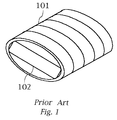
- Fig. 1 shows a sectional view of a typical flextensional transducer.
- the flextensional transducer essentially consists of two parts. One is an oval shaped shell and the other is a drive unit positioned within the oval shell.
- the oval shell has a waterproof construction.
- the oval shell prevents water from sinking inside the shell.
- the oval shell also keeps its shape against hydrostatic pressure.
- a drive stack is installed along the major axis of the oval shell.
- the drive stack is made of thin blocks piled up in the major axis.
- Each thin block is made of piezoelectric ceramics. Those blocks have piezo electric effects, which cause strains when the blocks are electrically energised.
- Each block is electrically connected to an alternative current power source (not shown).
- An example of the circuit is disclosed in Fig. 2 of USP 3,258,738, titled "UNDER WATER TRANSDUCER APPARATUS".
- the drive stack is primarily compressed by the shell along the major axis.
- the compressing stress compensates tensile stress on the drive stack, which is fragile against such tensile stress because it is mainly made of piezoelectric ceramic blocks.
- the tensile stress is caused by distortion of the oval shell, and the distortion is caused by the hydrostatic pressure.
- the hydrostatic pressure is loaded uniformly on the oval surface of the shell, and the shell is distorted so that the oval shape is extended along the major axis. This distortion extends the drive stack along its major axis, causing the stack to generate a tensile stress.
- the maximum allowable tensile stress against the drive stack is 80 MPa, corresponding to a depth of about 150m under water in the case of a 350Hz flextensional design.
- the drive stack may not be able to bear the generated tensile stress if the flextransducer is sunk under the 150m depth.
- a 25MPa compressing stress is required in order to increase the depth limitation from 150m depth to 220m depth.
- the compressing stress is loaded on the drive stack by the oval shell in the most recently-designed transducers.
- the compressing stress was loaded with tension rods which extended parallel to the drive stack and compressed the drive stack.
- Fig. 2 shows the sectional view of the transducer.
- the oval shell does not bear the hydrostatic pressure, the oval shell has a round sectional shape 101a.
- the transducer is exposed in the air, the oval shell takes this shape.
- drive stack 102 Inside the oval shell 101, drive stack 102 has a round portion on both its ends. The round portions are each attached to the inner surface of the oval shell 101 at positions a1 and a2. The drive stack 101 is also compressed by the shell 101 in the lateral direction of the figure, and is slightly shortened.
- the oval shell is distorted by the hydrostatic pressure and adopts an extended shape 101b.
- the oval shell is pressed in the vertical direction of the figure, and elongated in the lateral direction of the figure.
- the inner surface moves according to the shell 101, but the round portions of the drive stack 101 do not follow.
- the round portions stay still against the inner surface. Accordingly, the points of attachment move from the point a1 to points b1 and b2, and from the point a2 to points b3 and b4.
- this invention provides an advanced flextensional transducer in which the drive stack has a strain compensator at least on one end of the stack.
- the strain compensator mechanically connects between the oval shell and the drive stack.
- the strain compensator preferably comprises a cylinder in one major end of the oval shell.
- a piston is inserted in the cylinder so that the piston can move along the major axis of the oval shell.
- the piston is stiffly connected to the drive stack at one end of the drive stack.
- the piston may vibrate along the major axis of the oval shell when the drive stack generates a relatively high vibration. Furthermore, the piston may also move relatively against the cylinder along the major axis of the oval shell when the flextensional transducer is sunk under water and the cylinder moves along the major axis of the oval shell according to the distortion of the oval shell.
- the piston has a hole penetrating through the piston along the direction of the major axis of the oval shell.
- the rest of the space in the cylinder in the shell is filled with fluid.
- the strain compensator has its own hydrostatic pressure, so that the strain compensator prevents certain vibrations or movements which have lower frequencies than the resonance frequency.
- Those low frequency vibrations contain, for example, oval shell distortion caused by the hydrostatic pressure.
- the hydrostatic pressure slowly progresses relatively in proportion to the depth of the flextensional transducer as the flextensional transducer sinks below the water.
- the hydrostatic pressure progress may be regarded as a vibration of extremely low frequency.
- sonic frequency vibration being generated in the drive stack is a relatively high vibration. For example, 350Hz vibration is employed in class IV flextensional transducer.
- Fig. 3 shows a sectional view of a flextensional transducer of a preferred embodiment of this invention.
- This drive stack 2 consists of piezoelectric ceramic blocks built up in a longitudinal direction. Each piezoelectric ceramic block distorts its dimension when it receives voltage therethrough. Accordingly, if the voltage alternates, the piezoelectric ceramic block then generates vibration itself. The frequency of vibration is substantially the same as the alternating voltage frequency.
- the drive stack 2 is elongated along the major axis of the oval shell 1. Both ends of the drive stack 2 are attached to the oval shell 1 with shafts 3 and 4. One end of the drive stack 2, which is shown as the left end in the figure, is stiffly attached to the oval shell 1 with shaft 3. The shaft 3 translates the vibration of the drive stack 2 to the oval shell 1 well. The other end of the drive stack, which is shown as the right end in the figure, is movably connected to the oval shell 1 with shaft 4, and piston 5 in the cylinder 7. The shaft 4 is mechanically supported by the oval shell 1 so that the shaft 4 is movable along its major axis.
- the drive stack 2 is also stiffly connected to the piston 5 with shaft 4.
- an O-ring 5a is provided on the shaft 4.
- Each O-ring 5a is attached to the cylinder 7 to prevent fluid flow out of the cylinder 7.
- the shaft 4 translates vibration from the drive stack 2 to the piston 5.
- the piston 5 is movably inserted in the cylinder 7.
- the cylinder 7 is, as shown in the figure 3, mounted on the oval shell 1 at one end of the oval shell 1.
- the cylinder 7 is elongated along the major axis of the oval shell 1.
- the piston 5 is slidable along the major axis of the oval shell 1.
- both plates 11 are tied with tension rods 12. Plates 11 and tension rods 12 have screw pitch, and both plates 11 compress the drive stack 2 by screwing the tension rods 11. Accordingly the drive stack 2 generates compressing stress.
- Fig. 4 shows an enlarged sectional view around the piston 5.
- the piston 5 has a penetrating hole 6 along its slidable direction.
- the cylinder 7 is filled with fluid 8.
- the hole 6 is filled with the fluid.
- the fluid has some adequate viscosity. Fluid passes through the hole 6 when the piston 5 slides inside the cylinder 7. When the fluid passes through the hole 6, the fluid resists the slide action of the piston 5 as a result of the viscosity of the fluid and dynamic friction between the fluid and the piston along the hole 6. The resistance depends on the fluid viscosity, the diameter of the hole 6, the diameter of the cylinder 7, and the sliding speed of the piston 5.
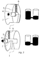
- Fig. 5 shows conceptional illustrations which explain that the fluid passes through the hole 6 when the piston 5 goes and returns slowly inside the cylinder 7.
- the fluid is good at transmitting vibrations. As stated above this occurs with vibrations of high frequency.
- the drive stack is provided with an alternating voltage of such high frequency. Accordingly, the vibration of the drive stack will be well transmitted to the oval shell, through the shaft 4, piston 5, fluid, and the cylinder 7.
- the piston 5 When the piston 5 is positioned at the extended side (shown as the right side in the figure), most of the fluid is gathered in the side of the cylinder 7 from which the shaft 4 extends. However, once the piston 5 slides to the shrink side (shown as the left side in the figure), the fluid passes through the hole 6 without resistance, and pours into the other side of the cylinder 7. It is apparently the same case that the cylinder 7 itself slides against the piston, in the major axis of the shaft 4.
- Fig. 6 shows the comparing explanation of fluid transition in the two different cases as cited above, of low frequency and high frequency.
- the fluid transits smoothly according to the piston slide, but in the high frequency case, the fluid cannot transit through an extremely high speed corresponding to piston slide speed.
- the fluid prevents the piston from sliding at high speed which corresponds to a high frequency of vibration.
- the piston 5 cannot slide at a sufficient amplitude as it can in the low frequency case.
- the cylinder 7 slides slowly like the low frequency case, because the hydrostatic pressure distorts the oval shell 1 and moves the cylinder 7 gradually.
- the piston 5 slides fast like the high frequency case, because the drive stack vibrates the piston at high frequency. Accordingly, the cylinder 7 and the piston 5 easily slide as a result of changing hydrostatic pressure, but they hardly slide as a result of vibration from the drive stack 2. As a result, the vibration from the drive stack 2 will be transmitted to the oval shell 1 without loss.
- Fig. 7 shows a second embodiment of this invention.
- the second embodiment resembles the first embodiment cited above, it is characterised in that the oval shell 1 comprises a path 8 and diaphragm 9.
- the path 8 connects the cylinder 7 with the space outside of the oval shell 1.
- diaphragm 9 covers the path 8. Because of the diaphragm 9, ocean water is prevented from pouring into the cylinder 7, and fluid is also prevented from ejecting out of the cylinder 7. However, the diaphragm 9 conducts the pressure outside of the oval shell 1 to the fluid inside the cylinder 7.
- the fluid keeps its pressure at an adequately high value. This pressure prevents the fluid from occurring cavitation.
- the diaphragm 9 keeps its flat shape when the oval shell 1 is exposed in the atmosphere. In this condition, the fluid filled in the cylinder 7 or the path 8 does not receive any pressure except atmosphere pressure. However, when the oval shell is thrown into the ocean, the diaphragm 9 receives hydrostatic pressure to be bent inwardly. Then the fluid in the path 8 also receives the same external pressure via the bend diaphragm 9.
- the pressure is then conducted to the fluid in the cylinder 7 through the path 8. Accordingly, the fluid in the cylinder 7 keeps the fluid pressure equal to the hydrostatic pressure outside the oval shell 1.
- Fig. 8 shows a third embodiment of this invention.
- an electric heater 10 is attached on the inner surface of the cylinder 7.
- the electric heater 10 is electrically connected to a power source (not shown) to be energised.
- the electric heater 10 When the electric heater 10 is energised, it raises fluid temperature. Then, the fluid pressure is also raised in the limited space inside the cylinder 7. This prevents the fluid from occurring cavitation around the piston 5, when the piston 5 vibrates with large amplitude. It ensures that vibrations are conducted through the fluid with high efficiency, from the shaft 4 to the oval shell 1.
- the third embodiment resembles the second embodiment cited above, in that raising the fluid pressure prevents cavitation.
- FIG. 9 shows fourth embodiment of this invention.
- oval shell 1 has a detachable spacer 1 a.
- the detachable spacer 1a can be attached after providing fluid into the cylinder 7.
Landscapes
- Physics & Mathematics (AREA)
- Engineering & Computer Science (AREA)
- Acoustics & Sound (AREA)
- Multimedia (AREA)
- Apparatuses For Generation Of Mechanical Vibrations (AREA)
- Transducers For Ultrasonic Waves (AREA)
Applications Claiming Priority (2)
| Application Number | Priority Date | Filing Date | Title |
|---|---|---|---|
| JP16250295A JP3323366B2 (ja) | 1995-06-28 | 1995-06-28 | 水中送受波器 |
| JP162502/95 | 1995-06-28 |
Publications (2)
| Publication Number | Publication Date |
|---|---|
| EP0751489A2 true EP0751489A2 (de) | 1997-01-02 |
| EP0751489A3 EP0751489A3 (de) | 1997-08-13 |
Family
ID=15755843
Family Applications (1)
| Application Number | Title | Priority Date | Filing Date |
|---|---|---|---|
| EP96304650A Withdrawn EP0751489A3 (de) | 1995-06-28 | 1996-06-24 | Flexiongespannter Wandler mit Zugkompensator |
Country Status (3)
| Country | Link |
|---|---|
| US (1) | US5768216A (de) |
| EP (1) | EP0751489A3 (de) |
| JP (1) | JP3323366B2 (de) |
Cited By (3)
| Publication number | Priority date | Publication date | Assignee | Title |
|---|---|---|---|---|
| US8159114B2 (en) | 2007-11-01 | 2012-04-17 | Qinetiq Limited | Transducer |
| CN105702244A (zh) * | 2014-11-28 | 2016-06-22 | 中国科学院声学研究所 | 一种嵌入式外部驱动iv型弯张换能器 |
| CN107403616A (zh) * | 2017-07-17 | 2017-11-28 | 哈尔滨工程大学 | 一种低频框架驱动式四边型弯张换能器 |
Families Citing this family (7)
| Publication number | Priority date | Publication date | Assignee | Title |
|---|---|---|---|---|
| US6781288B2 (en) * | 1999-01-27 | 2004-08-24 | Bae Systems Information And Electronic Systems Integration Inc. | Ultra-low frequency acoustic transducer |
| KR101227712B1 (ko) * | 2005-05-30 | 2013-01-29 | 조운현 | 굴곡탄성 피스톤 음파변화기 |
| GB0721433D0 (en) * | 2007-11-01 | 2007-12-12 | Qinetiq Ltd | Temperature compensating flextensional transducer |
| FI121764B (fi) | 2008-12-31 | 2011-03-31 | Patria Aviat Oy | Nesteessä oleva värähtelijä |
| US9417017B2 (en) | 2012-03-20 | 2016-08-16 | Thermal Corp. | Heat transfer apparatus and method |
| US9612347B2 (en) * | 2014-08-14 | 2017-04-04 | Pgs Geophysical As | Compliance chambers for marine vibrators |
| PL3839447T3 (pl) * | 2019-12-16 | 2023-08-14 | Kistler Holding Ag | Przetwornik siły wim i profil obudowy dla takiego przetwornika siły wim |
Family Cites Families (8)
| Publication number | Priority date | Publication date | Assignee | Title |
|---|---|---|---|---|
| US2064911A (en) * | 1935-10-09 | 1936-12-22 | Harvey C Hayes | Sound generating and directing apparatus |
| US3258738A (en) * | 1963-11-20 | 1966-06-28 | Honeywell Inc | Underwater transducer apparatus |
| US4420826A (en) * | 1981-07-06 | 1983-12-13 | Sanders Associates, Inc. | Stress relief for flextensional transducer |
| EP0297101B1 (de) * | 1986-03-19 | 1992-04-22 | The Secretary of State for Defence in Her Britannic Majesty's Government of the United Kingdom of Great Britain and | Flexionsgespannter wandler |
| US4845687A (en) * | 1988-05-05 | 1989-07-04 | Edo Corporation, Western Division | Flextensional sonar transducer assembly |
| US4964106A (en) * | 1989-04-14 | 1990-10-16 | Edo Corporation, Western Division | Flextensional sonar transducer assembly |
| FR2672179B1 (fr) * | 1991-01-25 | 1993-04-16 | Thomson Csf | Transducteur acoustique flextenseur pour immersion profonde. |
| US5363346A (en) * | 1993-01-07 | 1994-11-08 | The United States Of America As Represented By The Secretary Of The Navy | Conforming tuning coupler for flextensional transducers |
-
1995
- 1995-06-28 JP JP16250295A patent/JP3323366B2/ja not_active Expired - Lifetime
-
1996
- 1996-06-24 EP EP96304650A patent/EP0751489A3/de not_active Withdrawn
- 1996-06-26 US US08/672,028 patent/US5768216A/en not_active Expired - Fee Related
Cited By (5)
| Publication number | Priority date | Publication date | Assignee | Title |
|---|---|---|---|---|
| US8159114B2 (en) | 2007-11-01 | 2012-04-17 | Qinetiq Limited | Transducer |
| US8659209B2 (en) | 2007-11-01 | 2014-02-25 | Qinetiq Limited | Transducer |
| CN105702244A (zh) * | 2014-11-28 | 2016-06-22 | 中国科学院声学研究所 | 一种嵌入式外部驱动iv型弯张换能器 |
| CN105702244B (zh) * | 2014-11-28 | 2019-09-24 | 中国科学院声学研究所 | 一种嵌入式外部驱动iv型弯张换能器 |
| CN107403616A (zh) * | 2017-07-17 | 2017-11-28 | 哈尔滨工程大学 | 一种低频框架驱动式四边型弯张换能器 |
Also Published As
| Publication number | Publication date |
|---|---|
| US5768216A (en) | 1998-06-16 |
| EP0751489A3 (de) | 1997-08-13 |
| JPH0918988A (ja) | 1997-01-17 |
| JP3323366B2 (ja) | 2002-09-09 |
Similar Documents
| Publication | Publication Date | Title |
|---|---|---|
| EP0826157B1 (de) | Antriebsanordnung für akustische quellen | |
| US5959939A (en) | Electrodynamic driving means for acoustic emitters | |
| US4384351A (en) | Flextensional transducer | |
| NO337379B1 (no) | Driversammenstilling for en seismisk vibrator med to resonansfrekvenser | |
| SE514569C2 (sv) | Drivanordning för hydroakustiska sändare samt användning av anordningen för sändning av hydroakustiska vågor i en vätska | |
| EP0689681B1 (de) | Steueranordnung für akustischen quellen | |
| US4068209A (en) | Electroacoustic transducer for deep submersion | |
| US5768216A (en) | Flexitensional transducer having a strain compensator | |
| Larson et al. | State switched transducers: A new approach to high-power, low-frequency, underwater projectors | |
| US5321333A (en) | Torsional shear wave transducer | |
| KR102765315B1 (ko) | 플렉스텐셔널 저주파 음향 프로젝터 | |
| US5701277A (en) | Electro-acoustic transducers | |
| EP0363032A2 (de) | Flexeinsgespannter Wandler | |
| KR20000029497A (ko) | 낮은공진주파수를갖는굴곡판음파변환기 | |
| EP3341762A1 (de) | Verteilte seismische quellenanordnung zur verwendung in marinen umgebungen | |
| EP0400497B1 (de) | Vorrichtung in akustischen Sendern | |
| US10139504B2 (en) | Distributed seismic source array for use in marine environments | |
| AU2014343763B2 (en) | Tunable resonance in a resonating gas seismic source | |
| US4982386A (en) | Underwater acoustic waveguide transducer for deep ocean depths | |
| Oswin et al. | Frequency, power and depth performance of class IV flextensional transducers | |
| US5469406A (en) | Method of emitting very low frequency high power acoustic waves, and corresponding transducers therefor | |
| Letiche et al. | Transducers for low-frequency communications | |
| SU1140076A1 (ru) | Акустический преобразователь |
Legal Events
| Date | Code | Title | Description |
|---|---|---|---|
| PUAI | Public reference made under article 153(3) epc to a published international application that has entered the european phase |
Free format text: ORIGINAL CODE: 0009012 |
|
| AK | Designated contracting states |
Kind code of ref document: A2 Designated state(s): FR GB SE |
|
| PUAL | Search report despatched |
Free format text: ORIGINAL CODE: 0009013 |
|
| AK | Designated contracting states |
Kind code of ref document: A3 Designated state(s): FR GB SE |
|
| 17P | Request for examination filed |
Effective date: 19980107 |
|
| 17Q | First examination report despatched |
Effective date: 20000921 |
|
| 18D | Application deemed to be withdrawn |
Effective date: 20010205 |