EP0751676B1 - Vorrichtung und Verfahren zur Kompression und Wiedergabe von binären Mehrtonbildern - Google Patents
Vorrichtung und Verfahren zur Kompression und Wiedergabe von binären Mehrtonbildern Download PDFInfo
- Publication number
- EP0751676B1 EP0751676B1 EP96304697A EP96304697A EP0751676B1 EP 0751676 B1 EP0751676 B1 EP 0751676B1 EP 96304697 A EP96304697 A EP 96304697A EP 96304697 A EP96304697 A EP 96304697A EP 0751676 B1 EP0751676 B1 EP 0751676B1
- Authority
- EP
- European Patent Office
- Prior art keywords
- dot
- pixel
- compressed
- tone
- pixels
- Prior art date
- Legal status (The legal status is an assumption and is not a legal conclusion. Google has not performed a legal analysis and makes no representation as to the accuracy of the status listed.)
- Expired - Lifetime
Links
- 238000000034 method Methods 0.000 title claims description 48
- 238000007906 compression Methods 0.000 description 45
- 230000006835 compression Effects 0.000 description 45
- 230000008569 process Effects 0.000 description 13
- 230000000694 effects Effects 0.000 description 12
- 238000006243 chemical reaction Methods 0.000 description 7
- 238000010586 diagram Methods 0.000 description 7
- 239000011159 matrix material Substances 0.000 description 5
- 238000003384 imaging method Methods 0.000 description 4
- 238000013144 data compression Methods 0.000 description 3
- 238000005516 engineering process Methods 0.000 description 3
- 230000009977 dual effect Effects 0.000 description 2
- 230000004044 response Effects 0.000 description 2
- 230000008901 benefit Effects 0.000 description 1
- 230000006837 decompression Effects 0.000 description 1
- 230000006870 function Effects 0.000 description 1
- 238000012986 modification Methods 0.000 description 1
- 230000004048 modification Effects 0.000 description 1
- 238000010606 normalization Methods 0.000 description 1
- 238000009877 rendering Methods 0.000 description 1
Images


Classifications
-
- H—ELECTRICITY
- H04—ELECTRIC COMMUNICATION TECHNIQUE
- H04N—PICTORIAL COMMUNICATION, e.g. TELEVISION
- H04N1/00—Scanning, transmission or reproduction of documents or the like, e.g. facsimile transmission; Details thereof
- H04N1/40—Picture signal circuits
- H04N1/405—Halftoning, i.e. converting the picture signal of a continuous-tone original into a corresponding signal showing only two levels
- H04N1/4055—Halftoning, i.e. converting the picture signal of a continuous-tone original into a corresponding signal showing only two levels producing a clustered dots or a size modulated halftone pattern
- H04N1/4056—Halftoning, i.e. converting the picture signal of a continuous-tone original into a corresponding signal showing only two levels producing a clustered dots or a size modulated halftone pattern the pattern varying in one dimension only, e.g. dash length, pulse width modulation [PWM]
-
- H—ELECTRICITY
- H04—ELECTRIC COMMUNICATION TECHNIQUE
- H04N—PICTORIAL COMMUNICATION, e.g. TELEVISION
- H04N1/00—Scanning, transmission or reproduction of documents or the like, e.g. facsimile transmission; Details thereof
- H04N1/41—Bandwidth or redundancy reduction
- H04N1/4105—Bandwidth or redundancy reduction for halftone screened pictures
Definitions
- the present invention relates to digital imaging apparatuses such as laser printers, ink jet printers, copying machines, and bit map displays, as well as to computer systems for performing digital image processing. More particularly, the present invention relates to improvements in the technology of compressing and restoring a multitone binary image.
- digital imaging apparatuses are designed to operate on images artificially expressed in the form of binary data.
- the binary data relate to picture elements of an image, referred to as pixels.
- digital imaging apparatuses could operate on images expressed as only the presence or absence of colour; the data relating to the pixels simply expressed either a dot or a blank space.
- each pixel has a plurality of dot areas. By dividing a pixel into dot areas, intermediate tones can be achieved. The tone of a given pixel thus relates to the number of shaded dot areas of the pixel.
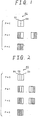
- Fig. 1 shows an example of a pixel PC of a multitone binary image.
- the pixel is divided into two dot areas, D1 and D2.
- An image made up of pixels having two dot areas each is referred to as a double-density image.
- the tone P of pixel PC can have three values, or stages, as shown in Fig. 1.
- Fig. 2 shows another example of a pixel PC of a multitone binary image.
- pixel PC is divided into three dot areas D1, D2, and D3.
- An image made up of pixels divided into three dot areas each is referred to as a triple-density image.
- the tone of the pixel can have one of four possible values, or stages.
- the six usable arrangements of the dot areas are shown in Fig. 2.
- a pixel PC of a multitone binary image may be divided into N dot areas, D1... DN.
- An image made up of pixels divided into N dot areas each may be referred to as an "N-times density" image.
- the N dot areas provide 2N usable arrangements of the dot areas.
- N-times density image can primitively be represented by an N-bit code, in which 1 bit corresponds to 1 dot area. Representing an N-times density image in such a primitive fashion can result in a large quantity of data, however, and can require a correspondingly large capacity memory.
- N-bit code in which 1 bit corresponds to 1 dot area.
- a very basic compression method is to use compressed codes for distinguishing among all the possible dot patterns in a pixel.
- For an N-times density image there are 2N usable dot patterns.
- the four patterns in a dual-density multitone image can be completely represented by two bits.
- a dual-density multitone image normally requires the use of 2-bit compressed codes.
- Three bits are required to represent the six patterns in a triple-density multitone image, and so 3-bit compressed codes are required.
- the length, in bits, of the compressed codes used for a particular N-times density image is referred to as the "depth" of the compressed code.
- the compressed codes used to represent the pixel tone of a pixel of a double-density multitone image have a depth of 2.
- the triple-density and quadruple-density multitone images require compression codes with a depth of three.
- the compressed codes of a compressed multitone image cannot be directly edited. That is, data compressed according to the above-described compression method cannot correctly be edited without first uncompressing the data.
- Editing operations include converting positive films to negative ones, overlapping characters on photographic paper, forming character drop-outs out of photographs, photographically drawing characters, and so forth.
- Such operations involve the manipulation of binary data through logical operations, such as a logical OR operation.
- logical operations on data compressed according to the basic compression method cannot be performed without causing corruption.
- a logical NOT calculation is applied to the compressed code.
- the calculation is made so as to have a code with all 1's or all 0's logically ORed with the photographic compressed code.
- a compressed code happens to have a value of all 1's or all 0's, it is simple to make the result of the logical operation conform to the result of applying that same logical operation to the uncompressed data representing the dot pattern.
- a compressed code having a value of all 0's may be allocated to a dot pattern with 0 dots, whereas a compressed code with all 1's may be allocated to a dot pattern with all N dots shaded.
- EP 0109005A discloses a method providing a halftone image wherein each pixel comprises a plurality of tone components defined by a multi-bit code, the tone components of each pixel being ordered as a function of the code of an immediately adjacent pixel.
- US 4150400 discloses methods of coarse-scan/fine-print character reproduction in which each coarse scan pixel is attributed with grey level information before compression. Upon decompression, the grey level information is operated on to activate a fine print device in which each coarse scan pixel is represented by a number of print dots. The distribution of the printing of the dots in each coarse scan pixel may be biased towards a character region.
- WO95/33330 discloses a technique for rendering images on a binary marking machine.
- an object of the present invention is to provide a technology for compressing an N-times density multitone image in which the compression effect is achievable even when N is small.
- Another object of the present invention is to compress the data of an N-times density multitone image so that editing operations on the compressed data are feasible.
- Still another object of the present invention is to make it possible to compress and restore an N-times density multitone image in a substantially simple and uncomplicated manner.
- this invention provides an apparatus for restoring a compressed multitone image, comprising:
- this invention provides a method of restoring a compressed multitone image, comprising:
- a compressed code of M bits in depth is used to represent the N + 1 tones of an N-times density image.
- An important feature of the invention is that, in the process of restoring the dot pattern of each pixel from the compressed codes, the compressed codes of adjoining pixels are referred to in addition to the compressed code of the particular pixel being restored.
- the dot pattern of each pixel so restored contains a number of dots corresponding to the tone represented by the compressed code of each pixel, and the dots are situated closer to the one of the two adjoining pixels having a darker tone.
- a compressed code may have a number of bits sufficient for distinguishing among N + 1 tones of an N-times density image.
- the depth of 2 bits is equal to the depth of the compressed code for the double-density image under the aforesaid basic compression method, and is 1 bit less than the depth of the compressed code for a triple-density image compressed according to the basic compression method.
- the quantity of data generated by compressing a triple-density image according to the present invention is only 2/3 of that generated by compressing the same triple-density image according to the basic compression method.
- the number of distinguishable tones according to the present invention is 4/3 of the number of tones distinguishable in an identical amount of compressed data, compared to the basic compression method.
- the compression effect is achievable even in the N-times density image where N is as small as 3.
- the compression effect is, needless to say, also achievable when N is large.
- N 7
- the choice between the two dot patterns of an intermediate tone pixel is made so that the dots are closer to the one of the two adjoining pixels (i.e., closer to the left side adjoining pixel or closer to the right side adjoining pixel) which has a darkest tone value.
- the just-described method is used for data compression of the binary data of the triple-density image, it is possible correctly and accurately to restore six dot patterns (as shown in Fig. 2) from compressed codes that are only 2 bits in length.
- the present invention achieves a compression effect when N is as small as 3, since the depth of the compressed codes is less than the number of dot areas of the pixel.
- N 3 in the description of the preferred embodiment of the present invention given below, the present invention is applicable also to other values of N. Moreover, though a description will be given of an instance in which the present invention is applied to image processing in printers, according to the preferred embodiment thereof, the present invention is applicable to image processing in, for example, computers, copying machines, and the like.
- Fig. 1 is a diagrammatic view of the usable dot patterns of a double-density image.
- Fig 2 is a diagrammatic view of the usable dot patterns of a triple-density image.
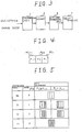
- Fig. 3 is a block diagram showing a configuration of an image processing system for a printer as an embodiment of the present invention.
- Fig. 4 is a diagrammatic view of three adjoining pixels.
- Fig. 5 is a diagram illustrating the interrelationship among the pixel tones, the compressed codes, and the dot patterns of a triple-density image.
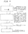
- Fig. 6 is a flowchart showing a conversion process flow in a compression unit.
- Fig. 7 is a diagram illustrating a specific example of the conversion process performed in the compression unit.
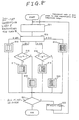
- Fig. 8 is a flowchart showing a conversion process flow in a bit-map generating unit.
- Fig. 9 is a diagram illustrating the hardware configuration of the bit-map generating unit.
- Fig. 3 is a block diagram showing a configuration of an image processing system for a printer as an embodiment of the present invention.
- the source data relates to a triple-density multitone image.
- a compression unit 1 receives source data relating to a multitone image. Each pixel in the source data is an 8-bit code capable of expressing one of 256 tones. The compression unit 1 converts the respective 8-bit code of each source data pixel to a corresponding 2-bit compressed code. The 2-bit compressed code is deep enough to express 4 different tones. Thus, the compression unit 1 compresses source data to provide, as an output, compressed image data.
- the conversion method used in compression unit 1 can be any one of several adoptable conversion methods.
- One such method described below in connection with this preferred embodiment, uses a dither matrix.
- the compressed image data in which the respective tone of each pixel is in the form of a 2-bit compressed code, is output from the compression unit 1 and is stored in a memory 3 as stored compressed image data.
- a bit-map generating unit 5 reads the stored compressed image data from the memory 3 and converts the data to bit-mapped data corresponding to a dot pattern of a triple-density image. More specifically, the bit-map generating unit 5 converts the 2-bit compressed code of each pixel to a 3-bit bit-mapped code in which each of the three bits represents either a dot or a blank space in a particular dot pattern.
- a bit-mapped code of 100 might be used to represent a first dot area having a dot, a second dot area having a blank space, and a third dot area having a blank space.
- a print engine 7 receives the bit-mapped data from the bit-map generating unit 5, and forms a pattern faithfully corresponding to this bit-mapped data, whereby it prints out the triple-density image on paper.
- Either or both of the compression unit 1 and the bit-map generating unit 5 may each be installed in the printer itself, or in the printer driver of a host computer connected to the printer. Either or both may be realised as a software process or as a hardware circuit.
- the compression unit 1 is a software process, and is performed by either the printer driver in the host computer or by a controller in the printer.
- the bit-map generating unit 5 is a custom hardware circuit especially designed to be used in the printer.
- Figs. 4 and 5 diagrammatically illustrate the principles of image compression and restoration according to this embodiment of the invention.
- Fig. 4 shows three consecutive pixels PC-1, PC0 and PC1. Each of these three pixels is on a certain line of a triple-density image. Pixel PC-1 adjoins PC0 on the left side thereof. PC1 adjoins PC0 on the right side thereof. Each of the three pixels has three respective dot areas. Pixels PC-1, P0, and P1 have respective tones P-1, P0, and P1.
- Fig. 5 diagrammatically illustrates the interrelationships among the tones, the 2-bit compressed codes, and the usable dot patterns with respect to the central pixel PC0.
- discussion will initially relate to the various tones, and then will turn to the various dot patterns.
- Fig 5 shows, there are two usable dot patterns in which only one of the three dot areas has a dot.
- One of the patterns has a single dot on the right-hand side, and the other has a single dot on the left-hand side.
- One of patterns has two dots on the right-hand side, and the other has two dots on the left-hand side.
- no dot patterns are defined in which dots are not together on the left or right-hand side of the pixel.
- each defined dot pattern has all of the dots grouped together in a group of one or more dots, and the group of one or more dots is either on the left or on the right-hand side.
- no pattern is defined which has a space on the left, a dot in the centre, and a space on the right.
- no pattern is defined which has a dot on the left, a space in the centre, and a dot on the right.
- the selection of which of the two dot patterns defined for a pixel of intermediate tone is based on the respective tones P-1 and P1 of the adjoining left-hand pixel PC-1 and the adjoining right-hand pixel PC1.
- the selection in this embodiment is made so that the group of dots in the dot pattern is closest to the adjoining pixel having a darker respective tone.
- the respective tones of pixels PC-1 and PC1 are the same, either of the two dot patterns of the intermediate tone pixel PC0 may be used.
- the one of the two dot patterns selected is the one in which the group of dots is closest to the right-hand side.
- Each of the two patterns has two dots and one blank space.
- the dot pattern selected is the one which places the two dots next to the adjoining pixel which has the darker tone with respect to the other adjoining pixel.
- Fig. 6 shows the flow of a process which is performed by the compression unit 1 for converting 8-bit data concerning each pixel of a 256-tone image into a 2-bit compressed code.
- Fig. 7 shows a specific example of the conversion process.
- the compression unit 1 first uses the dither method for converting the 256-tone image to a triple-density image in the bit-mapped data form.
- a threshold matrix having a size of vertical 6 pixels x horizontal 6 pixels as shown in Fig. 7A is employed, for example.
- the threshold matrix is formed with vertical 6 x horizontal 6 threshold values and each threshold value corresponds to each dot area in each pixel within an area of vertical 6 pixels x horizontal 6 pixels. Since the number of threshold values in this threshold matrix is 108 (i.e., vertical 6 pixels x 3 dot areas per pixel x horizontal 6 pixels) , the compression unit 1 normalises the tone P of each pixel of the 256-tone image.
- the normalised tone is P'.
- the compression unit 1 overlays the threshold matrix on each area of vertical 6 pixels x horizontal 6 pixels within the image thus normalised and compares the tone value P' of each pixel in that area with the three corresponding threshold values. Further, the compression unit 1 sets a binary value 1 (dot) in a dot area corresponding to a threshold value smaller than the tone value P' and a binary value 0 (blank space) in a dot area corresponding to the threshold value equal to or greater than the tone value P'.
- the tone P' of each pixel is converted into a 3-bit code representing a dot pattern having three dot areas.
- the area of vertical 6 pixels x horizontal 6 pixels having the normalised tone value P' as shown in Fig. 7B is converted into a dot pattern of the triple-density image of vertical 6 dots x horizontal 18 dots as shown in Fig. 7C.
- the compression unit 1 counts up the values 1 (dots) in each pixel (S3).
- the number of dots thus counted designates the tone P0 shown in Fig. 5
- the number of dots of each pixel in the dot pattern shown in Fig. 7C is like what is shown in Fig. 7D.
- the compression unit 1 converts the tone P0 (the number of dots) of each pixel into the 2-bit compressed code shown in Fig. 5 (S4) and writes the compressed code in the memory 3.
- Fig. 8 shows the flow of a process performed by the bit-map generating unit 5 to convert the stored compressed image data into bit-mapped data corresponding to dot patterns of the image.
- the process describes how a particular 2-bit compressed code for a given pixel is converted into a 3-bit bit-mapped code in which each of the three bits represents either a dot or a blank space in a particular dot pattern.
- step S15 is performed to compare the respective tone of pixel PC-1 with the respective tone of pixel PC1. Note that here, the higher the value of the tone, the darker the tone is. Thus, when PC1 (i.e., the right-hand adjoining pixel) has a tone P1 which is greater than the tone P-1 of pixel PC-1 (i.e., the left-hand adjoining pixel), step S17 is performed to produce a bit-map corresponding to a dot pattern in which the single dot is closest to the right-hand side of pixel PC0. When PC1 has a tone P1 equal to the tone P-1 of pixel PC-1, the same result obtains.
- step S18 is performed to produce a bit-map corresponding to a dot pattern in which the single dot is closest to the left-hand side of pixel PC0.
- Fig. 9 shows the hardware configuration of the bit-map generating unit 5.
- the bit-map generating unit 5 operates in synchronisation with a clock pulse, and outputs a 1-bit code representing one dot or one blank space in each period of the clock pulse. That is, a 3-bit bit-mapped code representing the dot pattern of a given pixel is produced every three clock pulse periods.
- a counter 11 is a 2-bit ternary counter which counts upward in response to the clock pulse. On receiving a reset pulse, the counter 11 initially resets the count to "00". Then the count is changed from “00" to "01", from “01” to “10”, and from “10” back to “00” in synchronisation with the clock pulse. Each time the count is returned to "00", the counter 11 outputs a carry pulse.
- a code generator 12 generates a 6-bit code in response to the 2-bit count output from counter 11.
- the particular 6-bit code output by the code generator 12 is provided, in parallel, to a code selector 14. For each of these three codes, the leftmost bit shall hereafter be referred to as the sixth bit and the rightmost shall be called the first bit.
- Code selector 14 is what actually outputs, one bit at a time, the bit-mapped data corresponding to the compressed codes.
- the code selector 14 outputs only a selected one of the six bits provided to it, in parallel, by code generator 12. In particular, code selector 14 outputs a "selected" one of the six bits.
- code generator 12 is providing "000111" to code selector 14 as a 6-bit code.
- the first bit thus has a value of "1”
- the sixth bit has a value of 0.
- the code selector has "selected” the sixth bit
- the output of the code selector is the value of the sixth bit (namely, "0").
- the counter has advanced to "01”.
- code generator 12 provides "001110" as the 6-bit code.
- the sixth bit now has a value of "0” If the code selector still selects the sixth bit, the output of the code selector is now a "0" When the counter advances to "10", the 6-bit code is "011100”. If the code selector still selects the sixth bit, the output of the code selector is now another "0". In this manner, the code selector has output "000” in three clock periods.
- This particular 3-bit code represents the dot pattern shown at Step S13 of Fig. 8.
- This 3-bit code represents the dot pattern shown at Step S17 of Fig. 8.
- a shift register 13 is a 2-bit, 3-stage shift register.
- the shift register 13 operates in synchronisation with a carry pulse from the counter 11 and also receives a 2-bit compressed code of a new pixel from the memory 3. Therefore, the compressed codes PC1, PC0 and PC-1 of three continuous pixels shown in Fig. 4 are held in the shift register 13.
- the compressed code of the left-hand pixel PC-1 is held at the initial stage ST-1; that of the central pixel PC0 at the second stage ST0; and that of the right-hand pixel PC1 at the third stage ST+1.
- the code selector 14 monitors the three compressed codes.
- the code selector 14 selects the sixth digit (i.e., the leftmost bit) of the 6-bit code from the code generator 12.
- the code selector 14 selects the third digit.
- the code selector 14 compares the compressed code from the initial stage ST-1 with that from the third stage ST+1; when the former is greater than the latter, the code selector 14 selects the fifth digit; otherwise it selects the first digit.
- the code selector 14 compares the compressed code from the initial stage ST-1 with that from the third stage ST+1. When the former is greater than the latter, it selects the fourth digit, and otherwise selects the second digit. As a result, the 3-bit bit-mapped code representing the dot pattern of the central pixel PC0 shown in Fig. 5 is serially output from the code selector 14.
- One advantage of the invention is that a logical operation, when performed on any of the compressed codes, has the same effect as if the operation had been applied to the corresponding dot pattern. That is, the 3-bit bit-mapped code, which represents a dot pattern of the triple-density image, and which has been output from the bit-map generating unit 5, is such that the result of a NOT calculation (inversion) with respect to the compressed code completely conforms to the result of a NOT calculation (inversion) with respect to the corresponding dot pattern. This is clear from the dot patterns of Fig. 5.
- the compressed code "00" corresponds to a dot pattern of all blank spaces.
- the compressed code becomes "11" which corresponds to a dot pattern of all dots.
- the compressed code "01”, for example, corresponds to a dot pattern of one dot and two blank spaces.
- the result is "10" which corresponds to a dot pattern having one blank space and two dots.
- the application of an inversion operation to the compressed code has the same effect as if it had been applied to the dot pattern.
- the triple-density image that is thus output after restoration of the data according to the invention is substantially similar to the triple-density image that would have been generated without compressing and restoring the data. That is, the data produced under the dither method (by compression unit 1) is almost the same as the data output by the bit-map generating unit 5.
- Fig. 7C shows the result of applying the dither method to the image data of Fig. 7A.
- Fig. 7E shows the corresponding output of the bit-map generating unit 5. The difference between the two figures appears in the pixel surrounded by a rectangle.
- N may be given a value other than those shown herein by way of example, the same effect is achievable.
- This invention provides an apparatus for restoring a compressed multitone image, said apparatus comprising:
- This invention further provides a method of restoring a compressed multitone image, said method comprising the steps of:
Landscapes
- Engineering & Computer Science (AREA)
- Multimedia (AREA)
- Signal Processing (AREA)
- Image Processing (AREA)
- Color, Gradation (AREA)
- Facsimile Image Signal Circuits (AREA)
- Compression Of Band Width Or Redundancy In Fax (AREA)
- Dot-Matrix Printers And Others (AREA)
Claims (8)
- Vorrichtung zum Wiederherstellen von einem komprimierten Multiton-Bild, umfassend:Punktmustererzeugungsmittel (5) zum Erzeugen eines Punktmusters mit N Punktflächen, wobei jedes eins von einem Punkt und einer Lehrstelle beim Erhalten eines komprimierten Codes jedes Pixels (PC0) und komprimierten Codes von beidseitig benachbarten Pixeln (PC-1, PC1) darstellt, wobei der komprimierte Code einen Ton jedes Pixels in einem Bild mit N+1 Tönen darstellt, wobei der komprimierte Code eine Tiefe von M Bits aufweist, und wobei die M Bits imstande sind, zwischen den N+1 Tönen zu unterscheiden, wobei die Anzahl der Punktflächen einen Punkt in dem Punktmuster jedes Pixels darstellen, der dem komprimierten Code des entsprechenden Pixels entspricht; dadurch gekennzeichnet, dassdas Punktmustermittel (5) so ist, dass wo eine Mehrzahl von Punktflächen in einem Pixel komprimiert sind, die Punktflächen zueinander benachbart angeordnet sind, und wobei die oder jede Punktfläche, die in dem Punktmuster einen Punkt darstellt, näher zu einem benachbarten Pixel, das einen dunkleren Ton von den beidseitig benachbarten Pixeln aufweist, liegt.
- Vorrichtung gemäß Anspruch 1, wobei die Tiefe M von dem komprimierten Code die folgende Gleichung erfüllt:
- Vorrichtung gemäß Anspruch 1 oder 2, wobei bei dem Ereignis, dass die benachbarten Pixel Töne gleicher Dunkelheit aufweisen, das Punktmustermittel (5) so angeordnet ist, dass der Punkt oder die Punkte näher zu einem vorbestimmten der benachbarten Pixel positioniert ist oder sind.
- Verfahren zum Wiederherstellen eines komprimierten Multitonbildes, umfassend:Bereitstellen eines komprimierten Codes mit einer Tiefe von M Bits und Darstellen eines Tons jedes Pixels in einem Bild mit N+1 Tönen, wobei die M Bits imstande sind, zwischen den N+1 Tönen zu unterscheiden,und Erzeugen eines Punktmusters mit N Flächen, wobei jede Fläche eins von einem Punkt und einer Leerstelle beim Erhalten eines komprimierten Codes jedes Pixels (PC0) und komprimierte Codes von den beidseitig benachbarten Pixeln (PC-1, PC1) darstellt, wobei die Anzahl der Punktflächen den Punkt, der den komprimierten Codes des entsprechenden Pixels entspricht, aufzeigt, dadurch gekennzeichnet, dass wenn eine Mehrzahl von Punktflächen in einem Pixel bereitgestell werden, die Punktflächen benachbart zueinander positioniert werden, und wobei die Punktfläche, die den Punkt in dem Punktmuster aufzeigt, näher zu einem benachbarten Pixel mit einem dunkleren Ton von den beidseitig benachbarten Pixeln, liegt.
- Verfahren zum Verarbeiten von Bilddaten, zugehörig zu Pixeln eines Multitonbinärbildes, wobei jede der Pixeln N Punktflächen aufweist, wobei die Pixeln ein laufendes Pixel (PC0) und benachbarte Pixel (PC-1, PC1) aufweisen, wobei das Verfahren gekennzeichnet ist durch:Definieren nur N+1 Tonwerte für die Pixel;Festlegen eines entsprechenden dieser Tonwerte für das laufende Pixel;Bereitstellen eines M-Bit-komprimierten Codes für das laufende Pixel, der dem festgelegten Tonwert entspricht, undWiederherstellen des komprimierten Bildes durch das Verfahren gemäß Anspruch 4.
- Verfahren gemäß Anspruch 5, wobei 2M nicht weniger ist als N+1, und wobei 2M nicht größer ist als 2N.
- Verfahren gemäß einem der Ansprüche 4 bis 6, wobei bei dem Ereignis, dass die benachbarten Pixel Töne gleicher Dunkelheit aufweisen, die Punktflächen näher zu einem vorbestimmten der benachbarten Pixel liegen.
- Vorrichtung zum Verarbeiten von Bilddaten, zugehörig zu Pixeln eines Multitonbildes, gekennzeichnet durch Erzeugungsmittel für komprimierte Codes (1) zum Erzeugen eines komprimierten Codes, der einen Ton jedes Pixels in einem Bild mit N+1 Tönen darstellt,
wobei der komprimierte Code eine Tiefe von M Bits aufweist, wobei die M Bits imstande sind, zwischen den N+1 Tönen zu unterscheiden; und Vorrichtung gemäß Anspruch 1.
Applications Claiming Priority (6)
| Application Number | Priority Date | Filing Date | Title |
|---|---|---|---|
| JP16055495 | 1995-06-27 | ||
| JP16055495 | 1995-06-27 | ||
| JP160554/95 | 1995-06-27 | ||
| JP10531696A JP3542685B2 (ja) | 1995-06-27 | 1996-04-25 | マルチトーンをもつバイナリ画像の圧縮及び復元のための装置及び方法 |
| JP10531696 | 1996-04-25 | ||
| JP105316/96 | 1996-04-25 |
Publications (3)
| Publication Number | Publication Date |
|---|---|
| EP0751676A2 EP0751676A2 (de) | 1997-01-02 |
| EP0751676A3 EP0751676A3 (de) | 1997-01-22 |
| EP0751676B1 true EP0751676B1 (de) | 2001-03-14 |
Family
ID=26445635
Family Applications (1)
| Application Number | Title | Priority Date | Filing Date |
|---|---|---|---|
| EP96304697A Expired - Lifetime EP0751676B1 (de) | 1995-06-27 | 1996-06-26 | Vorrichtung und Verfahren zur Kompression und Wiedergabe von binären Mehrtonbildern |
Country Status (4)
| Country | Link |
|---|---|
| US (1) | US5802209A (de) |
| EP (1) | EP0751676B1 (de) |
| JP (1) | JP3542685B2 (de) |
| DE (1) | DE69612039T2 (de) |
Families Citing this family (5)
| Publication number | Priority date | Publication date | Assignee | Title |
|---|---|---|---|---|
| US6119161A (en) * | 1997-02-28 | 2000-09-12 | International Business Machines Corporation | Managing connection requests in a dialup computer network |
| US6683702B1 (en) | 1999-07-07 | 2004-01-27 | Xerox Corporation | Compact-dot reproduction of scanned halftone screens |
| JP3927388B2 (ja) * | 2000-09-27 | 2007-06-06 | 株式会社リコー | 画像処理装置、画像処理方法及び記録媒体 |
| KR100484141B1 (ko) * | 2002-06-05 | 2005-04-18 | 삼성전자주식회사 | 영상 이진화 장치 및 방법 |
| JP2006074305A (ja) * | 2004-09-01 | 2006-03-16 | Ricoh Co Ltd | 階調再現方法、画像形成装置及びプリンタドライバ |
Family Cites Families (11)
| Publication number | Priority date | Publication date | Assignee | Title |
|---|---|---|---|---|
| US4084259A (en) * | 1973-11-30 | 1978-04-11 | The Mead Corporation | Apparatus for dot matrix recording |
| US4084196A (en) * | 1977-01-31 | 1978-04-11 | Dacom, Inc. | Electronic half-tone generating means for facsimile reproduction system |
| US4150400A (en) * | 1977-03-31 | 1979-04-17 | International Business Machines Corporation | Methods of a coarse-scan/fine-print character reproduction with compression |
| DE3002781A1 (de) * | 1980-01-26 | 1981-07-30 | Dr.-Ing. Rudolf Hell Gmbh, 2300 Kiel | Verfahren zur verbesserten bildwiedergabe in der reproduktionstechnik |
| US4532503A (en) * | 1982-11-08 | 1985-07-30 | International Business Machines Corporation | Sequence controlled pixel configuration |
| US4596993A (en) * | 1984-11-29 | 1986-06-24 | Polaroid Corporation | Thermal recording system and method |
| US4926251A (en) * | 1987-04-07 | 1990-05-15 | Kabushiki Kaisha Toshiba | Color image processing apparatus with image corrector |
| US4916545A (en) * | 1988-11-16 | 1990-04-10 | Eastman Kodak Company | Electronic graphic arts screener that suppresses Moire patterns using pseudo-random font selection |
| JPH04320160A (ja) * | 1991-04-19 | 1992-11-10 | Matsushita Electric Ind Co Ltd | 画像信号圧縮伸長装置および領域識別処理装置 |
| AU2653795A (en) * | 1994-05-27 | 1995-12-21 | Lasermaster Corporation | Technique for rendering images on a binary marking engine |
| US5625755A (en) * | 1994-07-01 | 1997-04-29 | Seiko Epson Corporation | Method and apparatus for tonal correction in binary printing devices by predistortion of image data utilizing ink reduction processing |
-
1996
- 1996-04-25 JP JP10531696A patent/JP3542685B2/ja not_active Expired - Lifetime
- 1996-06-26 EP EP96304697A patent/EP0751676B1/de not_active Expired - Lifetime
- 1996-06-26 DE DE69612039T patent/DE69612039T2/de not_active Expired - Lifetime
- 1996-06-26 US US08/672,044 patent/US5802209A/en not_active Expired - Lifetime
Also Published As
| Publication number | Publication date |
|---|---|
| DE69612039T2 (de) | 2001-11-08 |
| JPH0974485A (ja) | 1997-03-18 |
| DE69612039D1 (de) | 2001-04-19 |
| JP3542685B2 (ja) | 2004-07-14 |
| EP0751676A3 (de) | 1997-01-22 |
| US5802209A (en) | 1998-09-01 |
| EP0751676A2 (de) | 1997-01-02 |
Similar Documents
| Publication | Publication Date | Title |
|---|---|---|
| EP0707410B1 (de) | Vorrichtung zur adaptiven Filterung und Schwellenwertverarbeitung zur Verminderung der Bildkörnigkeit | |
| US5053887A (en) | Technique for producing a fine grained dithered halftone image having an increased number of gray levels | |
| US4414581A (en) | Image signal processing method and apparatus therefor | |
| US5216753A (en) | Halftone compression with sharpness preservation | |
| US5701401A (en) | Printing black and white reproducible color documents | |
| US6091511A (en) | Images with spatially varying spatial and gray level resolution | |
| US5956470A (en) | Text quality enhancement via resolution enhancement technique based on separating jaggedness detection and filtering | |
| EP0670654A1 (de) | Erzeugung von Mehrfachtonbildern | |
| US5598204A (en) | Image halftoning system capable of producing additional gradations | |
| US5150311A (en) | Electronic print-dot generation | |
| US6445404B1 (en) | Methods of providing lower resolution format data into a higher resolution format | |
| JPH08237482A (ja) | 2値印刷装置において、鮮明な色補正を行うための改良方法、および装置 | |
| US5802209A (en) | Apparatus and method for compressing and restoring binary image having multitone | |
| KR100354742B1 (ko) | 화상 데이터 처리장치 | |
| US5689344A (en) | Mitigation of tenting deletions in color xerographic printers | |
| US5611022A (en) | Color imaging | |
| US5390263A (en) | Method and apparatus for context sensitive post processing to select an appropriate modulation pattern for a pixel based upon neighboring pixels | |
| US5761347A (en) | Method and system for halftoning by tiling subsets of a threshold array over portions of an image | |
| EP0361538A1 (de) | Verfahren und Anordnung zur Randverstärkung bei der Reproduktion digitalisierter Multipegelbilder durch einen Printer mit konstanter Punktgrösse | |
| US6356360B1 (en) | Apparatus and method for rendering halftone dot structures using grey level dots | |
| US5930404A (en) | Image processing system and method | |
| JPH09294208A (ja) | 画像処理方法及び装置 | |
| CA2154100C (en) | Image halftoning system | |
| JP3984693B2 (ja) | 画像処理装置及び方法 | |
| US5446561A (en) | Method and apparatus for digital scale halftoning with variable screen structure for electrophotographic printing devices |
Legal Events
| Date | Code | Title | Description |
|---|---|---|---|
| PUAI | Public reference made under article 153(3) epc to a published international application that has entered the european phase |
Free format text: ORIGINAL CODE: 0009012 |
|
| PUAL | Search report despatched |
Free format text: ORIGINAL CODE: 0009013 |
|
| AK | Designated contracting states |
Kind code of ref document: A2 Designated state(s): DE FR GB |
|
| AK | Designated contracting states |
Kind code of ref document: A3 Designated state(s): DE FR GB |
|
| 17P | Request for examination filed |
Effective date: 19970711 |
|
| 17Q | First examination report despatched |
Effective date: 19990310 |
|
| GRAG | Despatch of communication of intention to grant |
Free format text: ORIGINAL CODE: EPIDOS AGRA |
|
| GRAG | Despatch of communication of intention to grant |
Free format text: ORIGINAL CODE: EPIDOS AGRA |
|
| GRAH | Despatch of communication of intention to grant a patent |
Free format text: ORIGINAL CODE: EPIDOS IGRA |
|
| GRAH | Despatch of communication of intention to grant a patent |
Free format text: ORIGINAL CODE: EPIDOS IGRA |
|
| GRAA | (expected) grant |
Free format text: ORIGINAL CODE: 0009210 |
|
| AK | Designated contracting states |
Kind code of ref document: B1 Designated state(s): DE FR GB |
|
| REF | Corresponds to: |
Ref document number: 69612039 Country of ref document: DE Date of ref document: 20010419 |
|
| ET | Fr: translation filed | ||
| REG | Reference to a national code |
Ref country code: GB Ref legal event code: IF02 |
|
| PLBE | No opposition filed within time limit |
Free format text: ORIGINAL CODE: 0009261 |
|
| STAA | Information on the status of an ep patent application or granted ep patent |
Free format text: STATUS: NO OPPOSITION FILED WITHIN TIME LIMIT |
|
| 26N | No opposition filed | ||
| REG | Reference to a national code |
Ref country code: FR Ref legal event code: PLFP Year of fee payment: 20 |
|
| PGFP | Annual fee paid to national office [announced via postgrant information from national office to epo] |
Ref country code: DE Payment date: 20150624 Year of fee payment: 20 Ref country code: GB Payment date: 20150624 Year of fee payment: 20 |
|
| PGFP | Annual fee paid to national office [announced via postgrant information from national office to epo] |
Ref country code: FR Payment date: 20150608 Year of fee payment: 20 |
|
| REG | Reference to a national code |
Ref country code: DE Ref legal event code: R071 Ref document number: 69612039 Country of ref document: DE |
|
| REG | Reference to a national code |
Ref country code: GB Ref legal event code: PE20 Expiry date: 20160625 |
|
| PG25 | Lapsed in a contracting state [announced via postgrant information from national office to epo] |
Ref country code: GB Free format text: LAPSE BECAUSE OF EXPIRATION OF PROTECTION Effective date: 20160625 |