EP0752155B1 - Kontaktanordnung - Google Patents
Kontaktanordnung Download PDFInfo
- Publication number
- EP0752155B1 EP0752155B1 EP95907133A EP95907133A EP0752155B1 EP 0752155 B1 EP0752155 B1 EP 0752155B1 EP 95907133 A EP95907133 A EP 95907133A EP 95907133 A EP95907133 A EP 95907133A EP 0752155 B1 EP0752155 B1 EP 0752155B1
- Authority
- EP
- European Patent Office
- Prior art keywords
- blade assembly
- trip lever
- blade
- integral
- blade member
- Prior art date
- Legal status (The legal status is an assumption and is not a legal conclusion. Google has not performed a legal analysis and makes no representation as to the accuracy of the status listed.)
- Expired - Lifetime
Links
- 239000004020 conductor Substances 0.000 claims description 5
- 239000011810 insulating material Substances 0.000 claims description 5
- 230000015572 biosynthetic process Effects 0.000 claims description 4
- 238000005755 formation reaction Methods 0.000 claims description 4
- 230000007246 mechanism Effects 0.000 description 3
- 230000008878 coupling Effects 0.000 description 2
- 238000010168 coupling process Methods 0.000 description 2
- 238000005859 coupling reaction Methods 0.000 description 2
- 239000000463 material Substances 0.000 description 2
- 229920003023 plastic Polymers 0.000 description 2
- 239000004033 plastic Substances 0.000 description 2
- 238000003466 welding Methods 0.000 description 2
- RYGMFSIKBFXOCR-UHFFFAOYSA-N Copper Chemical compound [Cu] RYGMFSIKBFXOCR-UHFFFAOYSA-N 0.000 description 1
- 230000000712 assembly Effects 0.000 description 1
- 238000000429 assembly Methods 0.000 description 1
- 229910052802 copper Inorganic materials 0.000 description 1
- 239000010949 copper Substances 0.000 description 1
- 238000002788 crimping Methods 0.000 description 1
- 230000005611 electricity Effects 0.000 description 1
- 230000005672 electromagnetic field Effects 0.000 description 1
- 238000011065 in-situ storage Methods 0.000 description 1
- 238000002347 injection Methods 0.000 description 1
- 239000007924 injection Substances 0.000 description 1
- 238000004519 manufacturing process Methods 0.000 description 1
- 238000000034 method Methods 0.000 description 1
Images


Classifications
-
- H—ELECTRICITY
- H01—ELECTRIC ELEMENTS
- H01H—ELECTRIC SWITCHES; RELAYS; SELECTORS; EMERGENCY PROTECTIVE DEVICES
- H01H71/00—Details of the protective switches or relays covered by groups H01H73/00 - H01H83/00
- H01H71/10—Operating or release mechanisms
- H01H71/50—Manual reset mechanisms which may be also used for manual release
- H01H71/52—Manual reset mechanisms which may be also used for manual release actuated by lever
- H01H71/526—Manual reset mechanisms which may be also used for manual release actuated by lever the lever forming a toggle linkage with a second lever, the free end of which is directly and releasably engageable with a contact structure
Definitions
- the invention relates to a blade assembly, particularly for use in circuit breakers.
- the invention relates to a blade assembly for a switch such as a circuit breaker, the blade assembly including a blade member, a trip lever, and a contact holder.
- WO-A-9116720 describes a blade assembly of this type.
- EP-A-0010678 describes a circuit breaker in which the blade member is formed from a plastic insulating material.
- Circuit breakers generally include a breaker mechanism mounted in a housing.
- Such breaker mechanisms generally comprise a large number of separate pieces which are assembled in the housing. Because of the number of pieces involved and the complexity of such mechanisms it is extremely difficult to automate the assembly operation.
- the invention is characterised in that:-
- the blade member comprises a pair of opposed side walls and connecting wall means extending between the side walls.
- the connecting wall means comprises a connecting web adjacent a contact end of the blade member and an end connecting wall adjacent an opposite end.
- the end connecting wall includes an extension defining an integral indicator flag.
- the trip lever mounting means comprises means for snap fittingly engaging with the trip lever.
- the trip lever mounting means comprises an integral pivot pin and the trip lever includes a recess corresponding to the integral pivot pin for snap fitting engagement.
- the integral spring means comprises a flexible arm which extends from the trip lever to engage with the blade member.
- the flexible arm is integral with the trip lever.
- the trip lever is of insulating material.
- the contact holder is of electrically conductive material and the contact holder mounting means and contact holder have interengaging formations for engaging the contact holder with the blade member.
- the contact mounting means includes opposed recesses in side walls of the blade member adjacent a contact end of the blade member.
- the assembly includes ramp means for guiding the contact holder into the recesses on fitting.
- the pawl mounting means comprises opposed pivot holes in the blade member to receive a pawl mounting pivot pin, the pawl being mounted to the pivot pin.
- the invention also provides a switch incorporating a blade assembly according to the invention.
- the invention further provides a circuit breaker incorporating a blade assembly according to the invention.
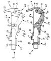
- FIG. 1 a blade assembly according to the invention and indicated by the reference numeral 1.
- the blade assembly 1 comprises a blade member 2A, a trip lever 2B, a contact holder 2C and, in this case, also a pawl 2D.
- At least the blade member 2A, and preferably also the trip lever 2B and the pawl 2D are of insulating, typically plastics material and are typically injection moulded.
- the blade member 2A has a rear contact end 5 and a front flag end 6 and comprises a pair of opposed side walls 3, 4 which are joined by a flag end connecting wall 8, an intermediate wall 10 and a connecting web 11 adjacent the contact end 5.
- the flag end connecting wall 8 has an extension 12 which defines, in use, an indicator flag as will be described in more detail below.
- the extension 12 may extend upwardly as illustrated or downwardly.
- Opposed holes 13 are provided in each side wall 3, 4 adjacent the flag end 6 to receive a pawl mounting pivot pin 14 which passes through a first pivot hole 15 in the pawl 2D for pivotally mounting the pawl 2D to the blade member.
- the pawl 2D in this case also includes a second pivot hole 19 for receiving a link as will be described below.
- a trip lever mounting pivot pin 20 is integrally moulded with the blade member 2A and extends between and projects from the blade side walls 3, 4 to define stub projections 20a.
- the pin 20 is sized to snap-fittingly engage with a correspondingly shaped recess 21 in the trip lever 2B.
- the trip lever 2B has a rear leg 26 and a forward leg 23 with a front nose portion 24 which engages with a corresponding recess 25 in the pawl 2D as will be particularly apparent from Fig. 3.
- An integral flexible arm 27 extends rearwardly from the trip lever 2B to engage underneath the web 11 of the blade member 2A. The arm 27 acts as a biassing spring to urge the nose 24 of the trip lever 2B into engagement with the recess 25 in the pawl 2D.
- the contact holder 2C is of electrically conductive material and snap-fittingly engages with the blade member 2A at the contact end 5.
- a moving contact 34 (Figs. 4 to 6) is fitted to the contact holder 2C, for example by riveting, welding or forming in situ.
- the contact holder 2C is of generally L-shape having an upright portion 32 and a horizontal portion 31 which are cut-away on both sides at 33 to engage with the blade member 2A.
- the blade side walls 3, 4 each have an inwardly extending ramp formation 35 and an inwardly extending stop rib 36 which are spaced-apart to define therebetween recesses 37 for engaging with the contact holder 2C.
- the upright portion 32 of the contact holder 2C is pressed forwardly to ride over the ramp formations 35 and snap into the recesses 37.
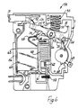
- the circuit breaker 50 has a housing 56 and includes a line terminal 51 for coupling to a source of electricity and a load terminal 52 for coupling to a load.
- a braided pigtail 53 is connected for example by crimping, welding or fixing, between the line terminal 51 and the contact holder 2C of the blade assembly 1.
- the stub projections 20a of the trip lever mounting pivot pin 20 of the assembly 1 engage with corresponding pivot recesses (not shown) in the housing 56. In a normal contacts closed position illustrated in Fig. 4 the moving contact 34 carried by the contact holder 2C is engaged with a fixed contact 58.
- the current path from the fixed contact 58 includes a coil 60 and a load conductor 61 to which the load terminal 52 is connected.
- the circuit breaker in this case also includes an arc runner 63 and an arc stack 64 which cooperate to break any arc formed when the circuit breaker opens and the contacts 34, 58 are separated under load.
- the contacts 34, 58 may be separated in response to operation of a bimetal (not shown) or by a rod 65 which is normally biased downwardly by a solenoid spring 62.
- the rod 65 is disposed within the coil 60 and is engagable against the rear leg 26 of the trip lever 2B of the blade assembly 1.
- a cam 68 has an operating handle 69.
- a link 70 connects the cam 68 and pawl 2D through the hole 19 in the pawl 2D.
- the housing 56 includes a viewing window 71 through which the flag 12 of the blade member 2A may be viewed when the contacts 34, 58 are in the off and tripped positions illustrated in Figs. 5 and 6.
- a spring 55 urges the blade assembly about the pivot defined by the stub projections 20a so that the moving contact 34 carried by the contact holder 2C is disengaged from the fixed contact 58.
- the circuit breaker is tripped either by a thermal overload as detected by a bimetal (not shown) or by a current surge actuator defined by the coil 60.
- a bimetal not shown
- a current surge actuator defined by the coil 60.
- the rod 65 In the normal closed position the rod 65 is downwardly biased by the solenoid spring 62 and current passing through the coil 60 sets up an electromagnetic field acting on the rod 65.
- the electromagnetic force set up in the coil 60 is disturbed by a current surge the rod 65 moves up to engage the rear leg 26 of the trip lever 2B of the blade assembly. This action pushes the forward leg 23 of the trip lever 2B downwardly so that the nose 24 of the trip lever 2B disengages from the recess in the pawl 2D.
- the spring 55 causes the contacts 34, 58 to separate.
- the blade assembly of the invention is of low mass and is without expensive conducting materials such as copper components. There are substantially less parts than in conventional blade assemblies so that material and assembly costs are substantially reduced. Thus, a much more economical and efficient method of manufacture may be achieved.
- the spring 55 may be of any suitable type such as a helical, coil or leaf spring.
Landscapes
- Breakers (AREA)
Claims (15)
- Blatt- oder Klingenbaugruppe (1) für einen Schalter (50) so wie einen Trennschalter (50), wobei die Blatt- oder Klingenbaugruppe (1) einschließt:dadurch gekennzeichnet, daßein Blattelement (2A);einen Schalthebel (2B); undeinen Kontakthalter (2C)das Blattelement (2A) aus Isoliermaterial besteht und ein integriertes Schalthebel-Befestigungsmittel (20), ein integriertes Kontakthalter-Befestigungsmittel (34,35,36) und ein Schaltklinken-Befestigungsmittel (13) umfaßt;der Schalthebel (2B) einen Nasenteil (24) zum Eingreifen in eine entsprechende Vertiefung (25) in einer Schaltklinke (2D) einschließt;und daß der Schalthebel (2B) weiter ein integriertes Vorspannfedermittel (27) einschließt, um den Nasenteil (24) des Schalthebels (2B) in Eingriff mit der Schaltklinke (2D) zu drücken.
- Blatt- oder Klingenbaugruppe nach Anspruch 1, bei der das im Schalthebel integrierte Vorspannfedermittel (27) einen flexiblen Arm (27) aufweist, der sich von dem Schalthebel (2B) erstreckt, um mit dem Blattelement (2A) in Eingriff zu treten.
- Blatt- oder Klingenbaugruppe nach Anspruch 1 oder 2, bei der das Blattelement (2A) eine integrierte Anzeigeflagge (8,12) einschließt.
- Blatt- oder Klingenbaugruppe nach einem der vorangegangenen Ansprüche, bei der das Blattelement (2A) ein Paar gegenüberliegender Seitenwände (3) und Verbindungswandmittel (8, 10, 11) aufweist, die sich zwischen den Seitenwänden (3) erstrecken.
- Blatt- oder Klingenbaugruppe nach Anspruch 4, bei der das Verbindungswandmittel (8,10,11) einen Verbindungssteg (11) neben einem Kontaktende des Blattelements (2A) und eine Endverbindungswand (8) benachbart einem gegenüberliegenden Ende aufweist.
- Blatt- oder Klingenbaugruppe nach Anspruch 5, bei der die Endverbindungswand (8) eine Verlängerung (12) einschließt, die eine integrierte Anzeigeflagge definiert.
- Blatt- oder Klingenbaugruppe nach einem der vorangegangenen Ansprüche, bei der das Schalthebel-Befestigungsmittel (20) Mittel (20) aufweist, um mit Schnappsitz mit dem Schalthebel (2B) in Eingriff zu treten.
- Blatt- oder Klingenbaugruppe nach Anspruch 7, bei der das Schalthebel-Befestigungsmittel (20) für Eingriff mit Schnappsitz einen integrierten Drehzapfen (20) aufweist und der Schalthebel (2B) eine Vertiefung (21) einschließt, die dem integrierten Drehzapfen (20) entspricht.
- Blatt- oder Klingenbaugruppe nach einem der vorangegangenen Ansprüche, bei der der Schalthebel (2B) aus Isoliermaterial besteht.
- Blatt- oder Klingenbaugruppe nach einem der vorangegangenen Ansprüche, bei der der Kontakthalter (2C) aus elektrisch leitfähigem Material besteht und das Kontakthalter-Befestigungsmittel (34,35,36) und der Kontakthalter (2C) ineinandergreifende Ausbildungen (32,35) haben, um den Kontakthalter (2C) mit dem Blattelement (2A) in Eingriff zu bringen.
- Blatt- oder Klingenbaugruppe nach Anspruch 10, bei der das Kontaktbefestigungsmittel gegenüberliegende Aussparungen (37) in den Seitenwänden (3) des Blattelements (2A) angrenzend an ein Kontaktende des Blattelements (2A) einschließt.
- Blatt- oder Klingenbaugruppe nach Anspruch 11, die Rampenmittel (35) zum Führen des Kontakthalters (2C) in die Aussparungen (37) beim Anbringen einschließt.
- Blatt- oder Klingenbaugruppe nach einem der vorangegangenen Ansprüche, bei der das Schaltklinken-Befestigungsmittel (13) gegenüberliegende Zapfenlöcher (13) in dem Blattelement (2A) aufweist, um einen Schaltklickenbefestigungs-Drehzapfen (14) aufzunehmen, wobei die Schaltklinke (2D) an dem Drehzapfen (14) angebracht ist.
- Schalter (50), der eine Blatt- oder Klingenbaugruppe (1) nach einem der vorangegangenen Ansprüche enthält.
- Trennschalter (50), der eine Blatt- oder Klingenbaugruppe (1) nach einem der Ansprüche 1 bis 13 enthält.
Applications Claiming Priority (3)
| Application Number | Priority Date | Filing Date | Title |
|---|---|---|---|
| IE940051 | 1994-01-21 | ||
| IE940051 | 1994-01-21 | ||
| PCT/IE1995/000005 WO1995020235A1 (en) | 1994-01-21 | 1995-01-23 | Blade assembly |
Publications (2)
| Publication Number | Publication Date |
|---|---|
| EP0752155A1 EP0752155A1 (de) | 1997-01-08 |
| EP0752155B1 true EP0752155B1 (de) | 1999-03-17 |
Family
ID=11040263
Family Applications (1)
| Application Number | Title | Priority Date | Filing Date |
|---|---|---|---|
| EP95907133A Expired - Lifetime EP0752155B1 (de) | 1994-01-21 | 1995-01-23 | Kontaktanordnung |
Country Status (6)
| Country | Link |
|---|---|
| EP (1) | EP0752155B1 (de) |
| AU (1) | AU1545095A (de) |
| CA (1) | CA2181728A1 (de) |
| DE (1) | DE69508389D1 (de) |
| IE (1) | IE950039A1 (de) |
| WO (1) | WO1995020235A1 (de) |
Families Citing this family (10)
| Publication number | Priority date | Publication date | Assignee | Title |
|---|---|---|---|---|
| SE509949C2 (sv) * | 1995-11-20 | 1999-03-29 | Enpece Sigma Ab | Anordning vid säkerhetsbrytare samt säkerhetsbrytare innefattande en sådan anordning |
| US6268989B1 (en) | 1998-12-11 | 2001-07-31 | General Electric Company | Residential load center with arcing fault protection |
| US6239962B1 (en) | 1999-02-09 | 2001-05-29 | General Electric Company | ARC fault circuit breaker |
| US6259340B1 (en) | 1999-05-10 | 2001-07-10 | General Electric Company | Circuit breaker with a dual test button mechanism |
| US6356426B1 (en) | 1999-07-19 | 2002-03-12 | General Electric Company | Residential circuit breaker with selectable current setting, load control and power line carrier signaling |
| US6232857B1 (en) | 1999-09-16 | 2001-05-15 | General Electric Company | Arc fault circuit breaker |
| US6466424B1 (en) | 1999-12-29 | 2002-10-15 | General Electric Company | Circuit protective device with temperature sensing |
| US6678137B1 (en) | 2000-08-04 | 2004-01-13 | General Electric Company | Temperature compensation circuit for an arc fault current interrupting circuit breaker |
| DE10133879B4 (de) * | 2001-07-12 | 2004-07-08 | Siemens Ag | Schaltgerät mit einem Schaltschloss |
| CZ299994B6 (cs) * | 2003-10-24 | 2009-01-14 | Jovean & Rogy Electrical Holding Co., Ltd | Spouštový mechanismus jistice |
Family Cites Families (5)
| Publication number | Priority date | Publication date | Assignee | Title |
|---|---|---|---|---|
| DE7500060U (de) * | 1975-01-03 | 1975-05-22 | Boshof R | Leitungsschutzschalter in Schmalbauweise und niedriger Bauart |
| DE7831956U1 (de) * | 1978-10-26 | 1979-02-08 | Siemens Ag, 1000 Berlin Und 8000 Muenchen | Schaltschloß mit Kniehebel |
| DE2927879C2 (de) * | 1979-07-11 | 1982-09-16 | Licentia Patent-Verwaltungs-Gmbh, 6000 Frankfurt | Kontaktanordnung für Leitungsschutzschalter |
| DE8401740U1 (de) * | 1983-10-11 | 1989-03-02 | Leopold Kostal GmbH & Co KG, 5880 Lüdenscheid | Elektrischer Schnappschalter |
| WO1991016720A1 (en) * | 1990-04-12 | 1991-10-31 | Square D Company | A method of manufacturing a circuit breaker |
-
1995
- 1995-01-23 EP EP95907133A patent/EP0752155B1/de not_active Expired - Lifetime
- 1995-01-23 AU AU15450/95A patent/AU1545095A/en not_active Abandoned
- 1995-01-23 WO PCT/IE1995/000005 patent/WO1995020235A1/en not_active Ceased
- 1995-01-23 CA CA002181728A patent/CA2181728A1/en not_active Abandoned
- 1995-01-23 DE DE69508389T patent/DE69508389D1/de not_active Expired - Lifetime
- 1995-01-23 IE IE950039A patent/IE950039A1/en not_active IP Right Cessation
Also Published As
| Publication number | Publication date |
|---|---|
| IE950039A1 (en) | 1995-07-26 |
| MX9602931A (es) | 1997-12-31 |
| WO1995020235A1 (en) | 1995-07-27 |
| CA2181728A1 (en) | 1995-07-27 |
| EP0752155A1 (de) | 1997-01-08 |
| AU1545095A (en) | 1995-08-08 |
| DE69508389D1 (de) | 1999-04-22 |
Similar Documents
| Publication | Publication Date | Title |
|---|---|---|
| EP1126490B1 (de) | Schutzschalter mit in senkrechten Ebenen arbeitendem Schaltschloss und Kniehebelmechanismus | |
| EP0496643B1 (de) | Thermischer Schalter/Ausschalter | |
| US6215378B1 (en) | Circuit breaker with dual function test button remote from test circuit | |
| EP0714549B1 (de) | Schaltgeräte | |
| US5694101A (en) | Circuit breaker | |
| EP0752155B1 (de) | Kontaktanordnung | |
| EP1126492B1 (de) | Schnellauslöser eines Schutzschalters mit einem durch den magnetischen Kreis einer Auslöseelektronik geführten Hauptleiter | |
| AU777311B2 (en) | Circuit breaker with bypass conductor commutating current out of the bimetal during short circuit interruption and method of commutating current out of bimetal | |
| EP0255955B1 (de) | Leistungstrennschalter | |
| CA1076175A (en) | Combination cover interlock and trip actuator | |
| US5565828A (en) | Circuit breaker | |
| US4549153A (en) | Residential circuit breaker with slot motor | |
| US20040257183A1 (en) | Circuit breaker including a cradle and a pivot pin therefor | |
| US4780697A (en) | Miniature circuit breaker with improved longevity | |
| US4812799A (en) | Miniature circuit breaker with improved longevity | |
| US4837545A (en) | Miniature circuit breaker with improved longevity | |
| US4546337A (en) | Residential circuit breaker with one piece slot motor | |
| US4339642A (en) | Current switching member for circuit breakers | |
| US6838961B2 (en) | Self-contained mechanism on a frame | |
| US5294901A (en) | Molded case circuit breaker insulated armature latch arrangement | |
| US4827233A (en) | Miniature circuit breaker with improved longivity | |
| US4072916A (en) | Stacked circuit breakers having high interrupting capacity | |
| CN100386837C (zh) | 用于断路器的改进的联锁机构及装有该联锁机构的断路器 | |
| US4764746A (en) | Circuit breaker | |
| US3959752A (en) | Narrow multi-pole circuit breaker having bodily movable instantaneous trip structure |
Legal Events
| Date | Code | Title | Description |
|---|---|---|---|
| PUAI | Public reference made under article 153(3) epc to a published international application that has entered the european phase |
Free format text: ORIGINAL CODE: 0009012 |
|
| 17P | Request for examination filed |
Effective date: 19960814 |
|
| AK | Designated contracting states |
Kind code of ref document: A1 Designated state(s): DE FR GB IT |
|
| 17Q | First examination report despatched |
Effective date: 19970218 |
|
| GRAG | Despatch of communication of intention to grant |
Free format text: ORIGINAL CODE: EPIDOS AGRA |
|
| GRAG | Despatch of communication of intention to grant |
Free format text: ORIGINAL CODE: EPIDOS AGRA |
|
| GRAH | Despatch of communication of intention to grant a patent |
Free format text: ORIGINAL CODE: EPIDOS IGRA |
|
| GRAH | Despatch of communication of intention to grant a patent |
Free format text: ORIGINAL CODE: EPIDOS IGRA |
|
| GRAA | (expected) grant |
Free format text: ORIGINAL CODE: 0009210 |
|
| AK | Designated contracting states |
Kind code of ref document: B1 Designated state(s): DE FR GB IT |
|
| PG25 | Lapsed in a contracting state [announced via postgrant information from national office to epo] |
Ref country code: IT Free format text: LAPSE BECAUSE OF FAILURE TO SUBMIT A TRANSLATION OF THE DESCRIPTION OR TO PAY THE FEE WITHIN THE PRESCRIBED TIME-LIMIT;WARNING: LAPSES OF ITALIAN PATENTS WITH EFFECTIVE DATE BEFORE 2007 MAY HAVE OCCURRED AT ANY TIME BEFORE 2007. THE CORRECT EFFECTIVE DATE MAY BE DIFFERENT FROM THE ONE RECORDED. Effective date: 19990317 |
|
| REF | Corresponds to: |
Ref document number: 69508389 Country of ref document: DE Date of ref document: 19990422 |
|
| ET | Fr: translation filed | ||
| PG25 | Lapsed in a contracting state [announced via postgrant information from national office to epo] |
Ref country code: DE Free format text: LAPSE BECAUSE OF FAILURE TO SUBMIT A TRANSLATION OF THE DESCRIPTION OR TO PAY THE FEE WITHIN THE PRESCRIBED TIME-LIMIT Effective date: 19990618 |
|
| PLBE | No opposition filed within time limit |
Free format text: ORIGINAL CODE: 0009261 |
|
| STAA | Information on the status of an ep patent application or granted ep patent |
Free format text: STATUS: NO OPPOSITION FILED WITHIN TIME LIMIT |
|
| 26N | No opposition filed | ||
| REG | Reference to a national code |
Ref country code: GB Ref legal event code: IF02 |
|
| PGFP | Annual fee paid to national office [announced via postgrant information from national office to epo] |
Ref country code: GB Payment date: 20021210 Year of fee payment: 9 |
|
| PGFP | Annual fee paid to national office [announced via postgrant information from national office to epo] |
Ref country code: FR Payment date: 20030107 Year of fee payment: 9 |
|
| PG25 | Lapsed in a contracting state [announced via postgrant information from national office to epo] |
Ref country code: GB Free format text: LAPSE BECAUSE OF NON-PAYMENT OF DUE FEES Effective date: 20040123 |
|
| GBPC | Gb: european patent ceased through non-payment of renewal fee |
Effective date: 20040123 |
|
| PG25 | Lapsed in a contracting state [announced via postgrant information from national office to epo] |
Ref country code: FR Free format text: LAPSE BECAUSE OF NON-PAYMENT OF DUE FEES Effective date: 20040930 |
|
| REG | Reference to a national code |
Ref country code: FR Ref legal event code: ST |