EP0752218A2 - Befestigungsanordnung für Sportschuhe oder Stiefel - Google Patents
Befestigungsanordnung für Sportschuhe oder Stiefel Download PDFInfo
- Publication number
- EP0752218A2 EP0752218A2 EP96110455A EP96110455A EP0752218A2 EP 0752218 A2 EP0752218 A2 EP 0752218A2 EP 96110455 A EP96110455 A EP 96110455A EP 96110455 A EP96110455 A EP 96110455A EP 0752218 A2 EP0752218 A2 EP 0752218A2
- Authority
- EP
- European Patent Office
- Prior art keywords
- stud
- rack
- aperture
- fastening arrangement
- elongated slot
- Prior art date
- Legal status (The legal status is an assumption and is not a legal conclusion. Google has not performed a legal analysis and makes no representation as to the accuracy of the status listed.)
- Granted
Links
- 238000006073 displacement reaction Methods 0.000 claims description 8
- 230000014759 maintenance of location Effects 0.000 claims description 4
- 239000002184 metal Substances 0.000 claims description 2
- 230000000717 retained effect Effects 0.000 claims 1
- 230000006978 adaptation Effects 0.000 description 2
- 238000010276 construction Methods 0.000 description 1
- 238000003780 insertion Methods 0.000 description 1
- 230000037431 insertion Effects 0.000 description 1
- 239000000463 material Substances 0.000 description 1
- 238000000034 method Methods 0.000 description 1
- 238000012986 modification Methods 0.000 description 1
- 230000004048 modification Effects 0.000 description 1
- 238000000465 moulding Methods 0.000 description 1
- 238000010008 shearing Methods 0.000 description 1
Images

Classifications
-
- A—HUMAN NECESSITIES
- A43—FOOTWEAR
- A43C—FASTENINGS OR ATTACHMENTS OF FOOTWEAR; LACES IN GENERAL
- A43C11/00—Other fastenings specially adapted for shoes
- A43C11/14—Clamp fastenings, e.g. strap fastenings; Clamp-buckle fastenings; Fastenings with toggle levers
- A43C11/1406—Fastenings with toggle levers; Equipment therefor
-
- A—HUMAN NECESSITIES
- A43—FOOTWEAR
- A43C—FASTENINGS OR ATTACHMENTS OF FOOTWEAR; LACES IN GENERAL
- A43C11/00—Other fastenings specially adapted for shoes
- A43C11/14—Clamp fastenings, e.g. strap fastenings; Clamp-buckle fastenings; Fastenings with toggle levers
- A43C11/1406—Fastenings with toggle levers; Equipment therefor
- A43C11/142—Fastenings with toggle levers with adjustment means provided for on the shoe, e.g. rack
- A43C11/1453—Fastenings with toggle levers with adjustment means provided for on the shoe, e.g. rack characterised by the shape of the teeth on the rack
Definitions
- the present invention refers to an improved fastening arrangement for sports shoes, in particular ski boots.
- upper and vamp can be used to indicate the same component part of the boot, as anyone skilled in the art will readily appreciate, so that the more general term of upper will be used in the following for reasons of greater simplicity and clarity.
- a first known solution lies in replacing the hooks so as to make the fastening arrangement either longer or shorter in accordance with the greater or smaller volumetric size of the foot of the skier.
- such a solution proves quite difficult and inconvenient, since, among other things, it requires quite great an effort to release the hook which must be fastened, and correspondingly released, by the action of the respective lever.
- a second, more rational solution calls for the serrated rack to be arranged in an adjustable manner on the instep portion of the boot upper.
- the rack is attached to the boot upper by means of a stud extending through an elongated slot-like aperture and fastened to an eccentric pivotally provided underneath the upper.
- an eccentric By causing the eccentric to rotate, a corresponding axial displacement of the stud of the rack is brought about, in such a manner as to bring the rack into a position enabling the fastening arrangement of the boot to be clamped.
- the arrangement according to the present invention substantially comprises a serrated rack that is fixed to the boot upper by means of adjusting means of the slot-and-stud type, which allow for a lengthwise displacement of the rack so as to enable the length of clamping to be adapted to the actual size of the foot, said arrangement being characterized in that the rack is attached upon the upper of the boot and is provided with a stud extending through an elongated slot in the upper, so that it can be selectively clamped in pre-defined positions with respect to the upper by means of a first rotation, that can be performed manually, by substantially a right angle of said rack with respect to its working position, slidably reset into a new desired position, and finally clamped again by means of a second reverse rotation opposite to said first rotation.
- the tightening of the front instep portions of the boot upper can be adjusted by clamping in a lever-like fashion an appropriate hook that is capable of engaging, with one of its end portions, said rack and, with the other end portion, a clamping means provided on the upper, said rack and said clamping means being provided on two distinct positions, one on the upper and one on the instep to be tightened.
- the adjustment of the tension of said hook can be performed by either adjusting the position of the rack or adjusting the position of the hook clamping means with respect to the corresponding supports.
- the present invention identically applies to the adjustment of the position of the rack and, alternatively, the adjustment of the position of the hook clamping means with respect to their supports, although for reasons of greater simplicity and clarity the invention will be described in the following description by referring solely to the adjustment of the position of the rack.
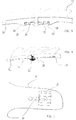
- the arrangement according to the present invention is shown as applied to the instep portion of an upper 10 of a ski boot (not shown), possibly subdivided into a plurality of similar instep portions in correspondence of the front portion of the boot.
- Said instep portion is provided on its upper portion with a rack 11 which, as will be shown more clearly further on, is capable of being caused to slide longitudinally with respect to the portion of upper 10 by rotating said rack 11 accordingly.
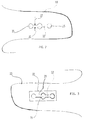
- the rack 11 is provided with a stud 14 extending downwards and passing through an elongated slot-like aperture 12 provided in said instep portion.
- said elongated slot-like aperture which has a pre-determined width 13 is shaped so as to provide a plurality of distinct enlarged sections 15 separated from each other, being preferably circular in their shape and arranged at substantially equal intervals along said elongated slot-like aperture.
- Said stud 14 has a cross-section which is substantially rectangular with respect to a plane a running parallel to the plane defined by a portion of the inner base of the rack; its shorter side 16 has a width which is smaller than the width 13 of said elongated slot-like aperture in the portions where it has no such enlarged sections 15, whereas its longer side 17 has a width which is larger than the width of said elongated slot-like aperture in the portions where it has no such enlarged section 15, but smaller than the width of said enlarged sections themselves, so as to be capable of being rotated freely within said enlarged sections when said stud is displaced in the corresponding zones or portions.
- the longer side 17 of said stud is substantially parallel to the ribs or serrations 18 of said rack.
- said rack is capable of being selectively clamped, with respect to the boot upper, in the positions in which its stud is positioned in correspondence of one of such enlarged sections of the elongated slot-like aperture.
- the position of the rack it is possible for the position of the rack to be displaced with respect to the boot upper by means of a first rotation by substantially a right angle of said rack relative to the working position thereof, so that said stud is positioned "edgewise” and is therefore enabled, owing to the above described mutual dimensional relations of said stud and the slot-like aperture, to cause the rack to slide into the new desired position and clamp it again in such a position by means of a second clamping rotation in the opposite direction with respect to said first rotation.
- retaining means may for instance be provided by forming the inner portion 19 of said stud, ie. its terminal portion facing the interior of the boot, in such a manner that it is given a substantially cylindrical shape.
- a washer 20, or similar means shall furthermore be provided for insertion on said substantially cylindrical portion 19 so as to be adapted to form a retaining element, preferably as an undercut, for said terminal portion of the stud, as this will be more clearly explained further on.
- the fastening arrangement for sports shoes in general, and ski boots in particular solves the problem associated with the dimensional adaptation to the wearer's or skier's foot by making use of constructively very simple and operationally quite practical and convenient means.
- the use of not always readily available tools or implements is in fact no longer required, while an adjustment can be performed at any time and under any condition, since a simple manual operation, which additionally does not require any particular effort or any particularly accurate handling, is all that is needed to carry it out.
- Said plate shall be machined in such a manner as to be provided with a slot-like opening 23 that fully corresponds in its dimensions and shape to the slot-like aperture 12 provided in the instep 10 of the boot upper, on which it is then laid on the inner side of the respective instep.
- the stud itself is of course made longer so as to enable it to get beyond the thickness of said plate and washer and come out from the inner side thereof.
- Such a solution has a further advantage deriving from the fact that, in this particular case, the displacement of the rack is actually guided by the slot-like opening 23 of the plate, thereby ensuring the highest possible extent of displacement accuracy, reliability, durability and jam-free operation.
- said rigid plate 22 were not present and the displacement of the rack were guided only by the edges of the elongated slot-like aperture 12, the latter being provided in the instep 10 of the boot upper which is made of a material which, albeit flexible, is not particularly resistant to shearing and fretting stresses, said edges would wear down very quickly, thereby making it difficult for the rack to be displaced and locked in place.
- said instep should appropriately be provided on its inner surface with protrusions 24, which may be formed by moulding, heading or any other suitable forming method, said protrusions being adapted to define a receptacle having such a shape and position as to firmly accomodate said plate in the desired position as described above.
Landscapes
- Health & Medical Sciences (AREA)
- Dentistry (AREA)
- General Health & Medical Sciences (AREA)
- Oral & Maxillofacial Surgery (AREA)
- Footwear And Its Accessory, Manufacturing Method And Apparatuses (AREA)
Applications Claiming Priority (2)
| Application Number | Priority Date | Filing Date | Title |
|---|---|---|---|
| IT1995PN000029U IT238855Y1 (it) | 1995-07-05 | 1995-07-05 | Dispositivo di chiusura per scarpe sportive |
| ITPN950029U | 1995-07-05 |
Publications (3)
| Publication Number | Publication Date |
|---|---|
| EP0752218A2 true EP0752218A2 (de) | 1997-01-08 |
| EP0752218A3 EP0752218A3 (de) | 1997-07-16 |
| EP0752218B1 EP0752218B1 (de) | 1999-03-17 |
Family
ID=11395029
Family Applications (1)
| Application Number | Title | Priority Date | Filing Date |
|---|---|---|---|
| EP96110455A Expired - Lifetime EP0752218B1 (de) | 1995-07-05 | 1996-06-28 | Befestigungsanordnung für Sportschuhe oder Stiefel |
Country Status (4)
| Country | Link |
|---|---|
| EP (1) | EP0752218B1 (de) |
| AT (1) | ATE177603T1 (de) |
| DE (1) | DE69601752T2 (de) |
| IT (1) | IT238855Y1 (de) |
Cited By (4)
| Publication number | Priority date | Publication date | Assignee | Title |
|---|---|---|---|---|
| EP1044620A1 (de) | 1999-04-16 | 2000-10-18 | BENETTON GROUP S.p.A. | Dispositif de fermeture pour chaussures |
| WO2003007746A2 (en) | 2001-07-19 | 2003-01-30 | Tecnica Spa | Adjustable closing device for sports shoe and shoe provided with at least one device of this type |
| EP1169932A3 (de) * | 2000-07-05 | 2003-08-13 | HTM SPORT S.p.A. | Verschluss, insbesondere für Sportschuhe |
| EP1602296A1 (de) * | 2004-06-04 | 2005-12-07 | Premec S.P.A. | Spannratsche insbesondere für Sportschuhe |
Family Cites Families (5)
| Publication number | Priority date | Publication date | Assignee | Title |
|---|---|---|---|---|
| DE1485857A1 (de) * | 1965-02-25 | 1970-06-11 | Loris Baso | Schnallenverschluss fuer Schuhe,insbesondere Ski- und Bergschuhe |
| DE2043679A1 (de) * | 1970-03-03 | 1972-03-09 | Baso, Loris, Padua (Italien) | Strammerverschluß an Skischuhen |
| DE2254711A1 (de) * | 1972-11-09 | 1974-05-16 | Loris Baso | Spannhebelverschluss, insbesondere fuer plastic-skischuhe |
| DE7504770U (de) * | 1975-02-17 | 1975-06-12 | Lederer J | Skistiefel |
| FR2733395B1 (fr) * | 1995-04-25 | 1997-07-04 | Salomon Sa | Fermeture reglable pour chaussure |
-
1995
- 1995-07-05 IT IT1995PN000029U patent/IT238855Y1/it active IP Right Grant
-
1996
- 1996-06-28 AT AT96110455T patent/ATE177603T1/de active
- 1996-06-28 DE DE69601752T patent/DE69601752T2/de not_active Expired - Lifetime
- 1996-06-28 EP EP96110455A patent/EP0752218B1/de not_active Expired - Lifetime
Cited By (4)
| Publication number | Priority date | Publication date | Assignee | Title |
|---|---|---|---|---|
| EP1044620A1 (de) | 1999-04-16 | 2000-10-18 | BENETTON GROUP S.p.A. | Dispositif de fermeture pour chaussures |
| EP1169932A3 (de) * | 2000-07-05 | 2003-08-13 | HTM SPORT S.p.A. | Verschluss, insbesondere für Sportschuhe |
| WO2003007746A2 (en) | 2001-07-19 | 2003-01-30 | Tecnica Spa | Adjustable closing device for sports shoe and shoe provided with at least one device of this type |
| EP1602296A1 (de) * | 2004-06-04 | 2005-12-07 | Premec S.P.A. | Spannratsche insbesondere für Sportschuhe |
Also Published As
| Publication number | Publication date |
|---|---|
| DE69601752T2 (de) | 1999-08-12 |
| ITPN950029V0 (it) | 1995-07-05 |
| DE69601752D1 (de) | 1999-04-22 |
| ITPN950029U1 (it) | 1997-01-05 |
| EP0752218A3 (de) | 1997-07-16 |
| EP0752218B1 (de) | 1999-03-17 |
| IT238855Y1 (it) | 2000-11-15 |
| ATE177603T1 (de) | 1999-04-15 |
Similar Documents
| Publication | Publication Date | Title |
|---|---|---|
| DE69709549T2 (de) | Snowboardstiefel und bindungsriemen | |
| US5467511A (en) | Shoelace fastening device | |
| US4620375A (en) | Snowshoe binding and ice crampon or the like | |
| US4377952A (en) | Pedal block for a cycle shoe | |
| US6073370A (en) | Snowboard boot power lacing configuration | |
| US6681971B2 (en) | Variably configurable securement arrangement in a load carrier | |
| US5314199A (en) | Convertible in-line roller skates | |
| US6155578A (en) | Binding mount | |
| US4205467A (en) | Ski boot | |
| US5660416A (en) | Clamping device for a multiple-part gliding board, in particular snowboard | |
| US5033210A (en) | Ski boot | |
| US4334368A (en) | Adjustable fastener for plastic ski boots | |
| DE112006001579T5 (de) | Schnürsenkel-Verriegelungseinrichtung | |
| US3866339A (en) | Shoe attachment for golfers | |
| EP0188818A1 (de) | Verschlusseinrichtung insbesondere für einen Skistiefel mit Einstieg von hinten | |
| US20030184031A1 (en) | Boot retaining device on a surfing-type snow board | |
| EP0752218B1 (de) | Befestigungsanordnung für Sportschuhe oder Stiefel | |
| US4330949A (en) | Shoe for cross-country running and cross-country ski | |
| US2230553A (en) | Ice skate | |
| US4157622A (en) | Fastener for footwear | |
| US4522379A (en) | Ski holder | |
| US4546558A (en) | Ski boot | |
| US4250595A (en) | Tool for opening and closing ski boots | |
| US4871336A (en) | Adjustable toe water ski binder | |
| AU743432B2 (en) | Device for fixing and removing stud seats for boots |
Legal Events
| Date | Code | Title | Description |
|---|---|---|---|
| PUAI | Public reference made under article 153(3) epc to a published international application that has entered the european phase |
Free format text: ORIGINAL CODE: 0009012 |
|
| AK | Designated contracting states |
Kind code of ref document: A2 Designated state(s): AT CH DE FR IT LI |
|
| PUAL | Search report despatched |
Free format text: ORIGINAL CODE: 0009013 |
|
| AK | Designated contracting states |
Kind code of ref document: A3 Designated state(s): AT CH DE FR IT LI |
|
| 17P | Request for examination filed |
Effective date: 19980113 |
|
| GRAG | Despatch of communication of intention to grant |
Free format text: ORIGINAL CODE: EPIDOS AGRA |
|
| 17Q | First examination report despatched |
Effective date: 19980513 |
|
| GRAG | Despatch of communication of intention to grant |
Free format text: ORIGINAL CODE: EPIDOS AGRA |
|
| GRAH | Despatch of communication of intention to grant a patent |
Free format text: ORIGINAL CODE: EPIDOS IGRA |
|
| RAP1 | Party data changed (applicant data changed or rights of an application transferred) |
Owner name: BENETTON SPORTSYSTEM S.P.A. |
|
| GRAH | Despatch of communication of intention to grant a patent |
Free format text: ORIGINAL CODE: EPIDOS IGRA |
|
| GRAA | (expected) grant |
Free format text: ORIGINAL CODE: 0009210 |
|
| AK | Designated contracting states |
Kind code of ref document: B1 Designated state(s): AT CH DE FR IT LI |
|
| REF | Corresponds to: |
Ref document number: 177603 Country of ref document: AT Date of ref document: 19990415 Kind code of ref document: T |
|
| REG | Reference to a national code |
Ref country code: CH Ref legal event code: NV Representative=s name: PATENTANWALTSBUERO JEAN HUNZIKER Ref country code: CH Ref legal event code: EP |
|
| REF | Corresponds to: |
Ref document number: 69601752 Country of ref document: DE Date of ref document: 19990422 |
|
| ET | Fr: translation filed | ||
| RAP2 | Party data changed (patent owner data changed or rights of a patent transferred) |
Owner name: BENETTON GROUP S.P.A. |
|
| PLBE | No opposition filed within time limit |
Free format text: ORIGINAL CODE: 0009261 |
|
| STAA | Information on the status of an ep patent application or granted ep patent |
Free format text: STATUS: NO OPPOSITION FILED WITHIN TIME LIMIT |
|
| 26N | No opposition filed | ||
| PGFP | Annual fee paid to national office [announced via postgrant information from national office to epo] |
Ref country code: AT Payment date: 20140618 Year of fee payment: 19 Ref country code: CH Payment date: 20140620 Year of fee payment: 19 Ref country code: DE Payment date: 20140625 Year of fee payment: 19 |
|
| PGFP | Annual fee paid to national office [announced via postgrant information from national office to epo] |
Ref country code: FR Payment date: 20140617 Year of fee payment: 19 |
|
| PGFP | Annual fee paid to national office [announced via postgrant information from national office to epo] |
Ref country code: IT Payment date: 20140630 Year of fee payment: 19 |
|
| REG | Reference to a national code |
Ref country code: DE Ref legal event code: R119 Ref document number: 69601752 Country of ref document: DE |
|
| PG25 | Lapsed in a contracting state [announced via postgrant information from national office to epo] |
Ref country code: IT Free format text: LAPSE BECAUSE OF NON-PAYMENT OF DUE FEES Effective date: 20150628 |
|
| REG | Reference to a national code |
Ref country code: CH Ref legal event code: PL |
|
| REG | Reference to a national code |
Ref country code: AT Ref legal event code: MM01 Ref document number: 177603 Country of ref document: AT Kind code of ref document: T Effective date: 20150628 |
|
| REG | Reference to a national code |
Ref country code: FR Ref legal event code: ST Effective date: 20160229 |
|
| PG25 | Lapsed in a contracting state [announced via postgrant information from national office to epo] |
Ref country code: CH Free format text: LAPSE BECAUSE OF NON-PAYMENT OF DUE FEES Effective date: 20150630 Ref country code: DE Free format text: LAPSE BECAUSE OF NON-PAYMENT OF DUE FEES Effective date: 20160101 Ref country code: LI Free format text: LAPSE BECAUSE OF NON-PAYMENT OF DUE FEES Effective date: 20150630 |
|
| PG25 | Lapsed in a contracting state [announced via postgrant information from national office to epo] |
Ref country code: AT Free format text: LAPSE BECAUSE OF NON-PAYMENT OF DUE FEES Effective date: 20150628 Ref country code: FR Free format text: LAPSE BECAUSE OF NON-PAYMENT OF DUE FEES Effective date: 20150630 |