EP0752803A2 - Arrangement pour la prévention d'un mauvais fonctionnement de capteur dans four à microondes - Google Patents
Arrangement pour la prévention d'un mauvais fonctionnement de capteur dans four à microondes Download PDFInfo
- Publication number
- EP0752803A2 EP0752803A2 EP96100105A EP96100105A EP0752803A2 EP 0752803 A2 EP0752803 A2 EP 0752803A2 EP 96100105 A EP96100105 A EP 96100105A EP 96100105 A EP96100105 A EP 96100105A EP 0752803 A2 EP0752803 A2 EP 0752803A2
- Authority
- EP
- European Patent Office
- Prior art keywords
- sensor
- air duct
- microwave oven
- air
- disposed
- Prior art date
- Legal status (The legal status is an assumption and is not a legal conclusion. Google has not performed a legal analysis and makes no representation as to the accuracy of the status listed.)
- Granted
Links
Images


Classifications
-
- H—ELECTRICITY
- H05—ELECTRIC TECHNIQUES NOT OTHERWISE PROVIDED FOR
- H05B—ELECTRIC HEATING; ELECTRIC LIGHT SOURCES NOT OTHERWISE PROVIDED FOR; CIRCUIT ARRANGEMENTS FOR ELECTRIC LIGHT SOURCES, IN GENERAL
- H05B6/00—Heating by electric, magnetic or electromagnetic fields
- H05B6/64—Heating using microwaves
- H05B6/642—Cooling of the microwave components and related air circulation systems
-
- H—ELECTRICITY
- H05—ELECTRIC TECHNIQUES NOT OTHERWISE PROVIDED FOR
- H05B—ELECTRIC HEATING; ELECTRIC LIGHT SOURCES NOT OTHERWISE PROVIDED FOR; CIRCUIT ARRANGEMENTS FOR ELECTRIC LIGHT SOURCES, IN GENERAL
- H05B6/00—Heating by electric, magnetic or electromagnetic fields
- H05B6/64—Heating using microwaves
- H05B6/6447—Method of operation or details of the microwave heating apparatus related to the use of detectors or sensors
Definitions
- the present invention relates to a sensor malfunction prevention apparatus for a microwave oven, and particularly to a improved sensor malfunction prevention apparatus for a microwave oven capable of preventing a malfunction and an infrared ray sensor from being polluted by dusts, food debris or the like from a cooking chamber.
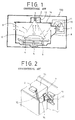
- Fig. 1 shows a convention microwave oven, which includes an infrared ray sensor 3 disposed at a sensor support 2 of a cavity upper plate 14.
- a cooking chamber 1 having a turntable 4 disposed at a central portion of the cooking chamber 1 is provided inside the microwave oven.
- a hole 13 connected to the cooking chamber 1 is formed at the lower portion of the sensor support 2.
- a magnetron 7 is formed at one side wall of the cooking chamber 1, and an air duct 15 is formed for guiding air flow from the magnetron 7 to the cooking chamber 1.
- a cooling fan 10 is disposed at one side wall of the microwave oven body 100 and near a periphery of the magnetron 7 and the air duct 15.
- Reference numeral 5 denotes a driving motor for driving the turntable 4
- 6 denotes a turntable support for supporting the turntable 4
- 8 denotes a wave guide for guiding microwave generated by the magnetron 7 to the cooking chamber 1
- 9 denotes an air discharging hole for discharging air in the cooking chamber 2 to the outside of the system
- 11 denotes a cooling fan guide.
- the conventional microwave oven 100 is directed to indirectly detecting the surface temperature of food placed on the upper surface of the turntable 4 through the holes 13 formed on the lower surface of the sensor support 2.
- the microcomputer (not shown) controls the output of the magnetron 7 in accordance with a certain value outputted from the infrared sensor 3 and automatically cooks food 12 on the turntable.
- the infrared sensor 3 is located at a central upper portion of the cooking chamber 1 at which it is easy to check the food 12 on the turntable and is directed to detecting infrared rays outputted from the food 12.
- the infrared ray sensor 3 is exposed to pollution materials such as heat, vapor, and gas which come out of the cooking chamber, the above-mentioned pollution materials can be easily attached to the surface of the bed ray sensor 3, so that sensing capability of the same is decreased, and the malfunction of the automatic cooking operation easily occurs.
- the infrared ray sensor 3 since the infrared ray sensor 3 is exposed to heat, the same is easily heated, so that the sensing capability of the sensor 3 is decreased, and the life spa of the same is also decreased.
- a sensor malfunction prevention apparatus for a microwave oven which includes a cooling fan; an air duct for guiding cooling air introduced into the interior of the microwave oven in cooperation with the cooling fan; a sensor support bracket disposed at a predetermined inner portion of the air duct; a sensor disposed at a predetermined portion of the sensor support bracket; a transparent prevention cover support disposed at the upper portion of the sensor support bracket for defining air openings between the transparent prevention cover and the sensor support bracket; ad a transparent prevention cover fixed to the transparent prevention support.
- a sensor malfunction prevention apparatus for a microwave oven which includes a cooling fan; an air duct having a slanted surface formed at one side thereof for guiding cooling air introduced into the interior of the microwave oven from the outside thereof into a cooking chamber in cooperation with the cooling fan; and a sensor disposed the slanted surface of the air duct.
- Fig. 1 is a cross-sectional view showing a conventional microwave oven and a sensor operation state thereof.
- Fig. 2 is a perspective view showing a conventional microwave oven equipped with a sensor.
- Fig. 3 is a cross-sectional view showing a microwave oven equipped with a sensor malfunction prevention apparatus and a air duct of a first embodiment according to the present invention.
- Fig. 4A is a cross-sectional view showing a microwave oven when a sensor malfunction prevention apparatus and a fan are operated, and a transparent prevention cover is lifted when a fan is operational according to a first embodiment of the present invention.
- Fig. 4B is a cross-sectional view showing a microwave oven when a sensor malfunction prevention apparatus is operated, and a fan is not operational, and a transparent prevention cover prevents a sensor of a first embodiment according to the present invention.
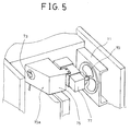
- Fig. 5 is a perspective view showing a microwave oven equipped with a sensor malfunction prevention apparatus of a second embodiment according to the present invention.
- Fig. 6A is a cross-sectional view showing a sensor malfunction prevention apparatus of a microwave oven of a second embodiment according to the present invention.
- Fig. 6B is a schematic cross-sectional view to show a sensor sensing range of a sensor malfunction prevention apparatus of a microwave oven of a second embodiment according to the present invention.
- Fig. 7 is a perspective view showing a sensor malfunction prevention apparatus of a third embodiment according to the present invention.
- Fig. 8 is a cross-sectional view showing a sensor malfunction prevention apparatus of a third embodiment according to the present invention.
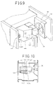
- Fig. 9 is a perspective view of a sensor malfunction prevention apparatus of a fourth embodiment according to the present invention.
- Fig. 10 is a cross-sectional view of a sensor malfunction prevention apparatus of a fourth embodiment according to the present invention.
- Fig. 3 shows a sensor malfunction prevention apparatus of a first embodiment according to the present invention, which includes a infrared ray sensor 33 disposed at a predetermined portion of a sensor support bracket 50 disposed at a cooling air flowing path inside an air duct 45.
- air openings 51 are formed at the upper portion of the sensor support bracket 50 for passing therethrough air and is spaced apart from the bed sensor 33.
- a transparent prevention cover 52 is affixed to a transparent prevention support 52a for blocking the front side of the infrared ray sensor 33.
- the cooling air flowing direction is denoted as the arrows in Fig. 4A.
- the transparent prevention film 52 is lowered in cooperation of the force of the gravity, so that the front side of the infrared sensor 33 is blocked. In this case, even though pollution materials are introduced toward the infrared ray sensor 33, the infrared ray sensor 33 is effectively prevented from the pollution materials.
- the pollution material flowing direction is indicated as the arrows in Fig. 4B which is drawn in a broken line.
- the air openings 51 is designed to have a proper function of lifting up the transparent prevention film 52 in cooperation with the air flowing pressure which is introduced into the air duct 45.
- the sensor support bracket 50 having the bared ray sensor 33 is downwardly slanted at a certain angle. That is, the upper portion of the same is slanted in the direction of the cooking chamber.
- the transparent prevention cover 52 is movable upwardly and downwardly, and the food in the cooking chamber 31 to be cooked can be easily sensed by the infrared ray sensor 33.
- Reference numeral 44 denotes a cavity upper plate.
- a downwardly slanted infrared ray sensor 73 is directed to sense foods on the turntable 74 at a wider angle.
- the infrared ray sensor 73 is disposed at a slated surface 75a of the air duct 75, pollution materials such as dust, heat and food debris which generated from the cooking chamber 61 is effectively blocked to flow toward the infrared ray sensor in cooperation of flow of the cooling air introduced into the air duct 75 by a cooling fan 70.
- reference numeral 71 denotes a cooling fan guide
- 77 denotes a magnetron.
- the sensor malfunction prevention apparatus of the third embodiment includes a separation plate 123 which is directed to separate an air duct 120 into an upper portion and a lower portion.
- the air duct 120 is separated into an upper path 121 and a lower path 122 by the separation plate 123, and the infrared ray sensor 113 is disposed at a predetermined portion of the upper path 121.
- the infrared ray sensor 113 is downwardly slated about the slated surface of the upper path 121.
- an entrance 121a of the upper path 121 is formed in an upper side direction of the magnetron 107 so that the cooling air flowing toward he upper portion of the magnetron 107 is effectively introduced toward the magnetron 107.
- the upper path 121 is formed at a certain position higher than the upper surface of the magnetron 107.
- the lower path 122 is disposed at the same height as the magnetron 107 so that the cooling air can be effectively introduced from the outside of the microwave oven body toward the magnetron 107 in cooperation with the cooling fan 110.
- the cooling air which does not contact with the magnetron 107 flows toward the upper path 121 in which the infrared ray sensor 113 is disposed, the infrared ray sensor 113 is not heated by itself, so that the malfunction of the infrared ray sensor 113 is effectively prevented.
- reference numeral 111 denotes a cooling fan guide.
- a separation plate 143 separating the interior of the air duct 140 into an upper portion and a lower portion is disposed inside the air duct 140 of the microwave oven body.
- the air duct 140 is separated into an upper path 141 and a lower path 142 by the separation plate 143.
- the infrared ray sensor 133 is disposed at a predetermined portion of the lower path 142 so as to effectively sense the food in the cooking chamber of the microwave oven.
- the infrared ray sensor 133 is downwardly slanted about the slanted surface of the lower path 142.
- a entrance 142a of the lower path 142 is downwardly formed from the magnetron 127 so that the cooling air flowing through the lower portion of the magnetron 127 can be effectively introduced toward the magnetron 127.
- the lower path 142 is positioned lower than the lower surface of the magnetron 127.
- the upper path 141 is position at the same height as the magnetron 127 so that the cooling air introduced from the outside of the microwave oven in cooperation with the cooling fan 130 can effectively cool the magnetron 127.
- the cooling air which does not contact with the magnetron 127 flows toward the lower path 142 in which the infrared ray sensor 133, the infrared ray sensor 133 is not heat by itself, so that the malfunction of the infrared ray sensor can be effectively prevented.
- reference numeral 131 denotes a cooling fan guide.
- the sensor malfunction prevention apparatus for a microwave oven of the present invention is directed to providing a infrared ray sensor in the air duct and a transparent prevention cover capable of effectively prevention pollution materials introduced thereto from the cooking chamber, so that malfunctions of the infrared ray sensor can be effectively prevented.
- the infrared ray sensor since the infrared ray sensor always comes into contact with the cooling air introduced into the air duct from the outside of the microwave oven, it is possible to prevent the infrared ray sensor from being heated and being polluted from pollution materials from the cooking chamber of the microwave oven.
Landscapes
- Physics & Mathematics (AREA)
- Electromagnetism (AREA)
- Electric Ovens (AREA)
- Control Of High-Frequency Heating Circuits (AREA)
Applications Claiming Priority (4)
| Application Number | Priority Date | Filing Date | Title |
|---|---|---|---|
| KR9516685 | 1995-07-07 | ||
| KR2019950016685U KR970006488U (ko) | 1995-07-07 | 1995-07-07 | 전자레인지의 센서 오동작방지장치 |
| KR2019950018211U KR0136607Y1 (ko) | 1995-07-24 | 1995-07-24 | 전자레인지의 센서 오동작 방지구조 |
| KR9518211 | 1995-07-24 |
Publications (3)
| Publication Number | Publication Date |
|---|---|
| EP0752803A2 true EP0752803A2 (fr) | 1997-01-08 |
| EP0752803A3 EP0752803A3 (fr) | 1998-01-14 |
| EP0752803B1 EP0752803B1 (fr) | 2000-05-24 |
Family
ID=26631089
Family Applications (1)
| Application Number | Title | Priority Date | Filing Date |
|---|---|---|---|
| EP96100105A Expired - Lifetime EP0752803B1 (fr) | 1995-07-07 | 1996-01-05 | Arrangement pour la prévention d'un mauvais fonctionnement de capteur dans four à microondes |
Country Status (5)
| Country | Link |
|---|---|
| US (1) | US5693248A (fr) |
| EP (1) | EP0752803B1 (fr) |
| CN (1) | CN1125271C (fr) |
| BR (1) | BR9600212A (fr) |
| DE (1) | DE69608500T2 (fr) |
Cited By (2)
| Publication number | Priority date | Publication date | Assignee | Title |
|---|---|---|---|---|
| EP0924964A3 (fr) * | 1997-12-22 | 2000-04-12 | Samsung Electronics Co., Ltd. | Four à microondes avec détecteur infrarouge |
| EP0917405A3 (fr) * | 1997-11-15 | 2000-04-12 | Lg Electronics Inc. | Dispositif pour prévenir la condensation sur un détecteur pour four à micro-ondes |
Families Citing this family (14)
| Publication number | Priority date | Publication date | Assignee | Title |
|---|---|---|---|---|
| JP3832317B2 (ja) * | 2001-11-13 | 2006-10-11 | 松下電器産業株式会社 | 高周波加熱装置 |
| CN100465610C (zh) * | 2005-04-25 | 2009-03-04 | 深圳大学 | 微波热解沉积致密化装置 |
| JP2009252633A (ja) * | 2008-04-09 | 2009-10-29 | Toshiba Corp | 誘導加熱調理器 |
| WO2011028729A1 (fr) | 2009-09-01 | 2011-03-10 | Manitowoc Foodservice Companies, Llc | Procédé et appareil pour une entrée d'air dans un dispositif de cuisson |
| JP2013032872A (ja) * | 2011-08-01 | 2013-02-14 | Sharp Corp | 加熱調理器 |
| US9752786B2 (en) | 2014-03-12 | 2017-09-05 | Haier Us Appliance Solutions, Inc. | Sensing system for a cooktop appliance with airflow protected sensor |
| US9528710B2 (en) * | 2014-03-12 | 2016-12-27 | Haier U.S. Appliance Solutions, Inc. | Sensing system for a cooktop appliance with airflow protected sensor |
| US20150302569A1 (en) * | 2014-04-22 | 2015-10-22 | General Electric Company | Sensing system for a cooktop appliance with airflow protected sensor |
| KR102082681B1 (ko) * | 2014-06-27 | 2020-03-02 | 한화디펜스 주식회사 | 이물질 방지 장치 |
| JP6523087B2 (ja) * | 2015-07-22 | 2019-05-29 | シャープ株式会社 | 加熱調理器 |
| CN108571757B (zh) * | 2017-03-08 | 2021-06-08 | 博西华电器(江苏)有限公司 | 吸油烟机的摄像装置及吸油烟机 |
| CA3081806A1 (fr) * | 2017-11-06 | 2019-05-09 | Paellas Alta Precision, S.L. | Module de cuisson d'aliments |
| CN108180517B (zh) * | 2017-12-27 | 2019-12-17 | 广东美的厨房电器制造有限公司 | 加热烹调装置 |
| DE102019206892A1 (de) * | 2019-05-13 | 2020-11-19 | BSH Hausgeräte GmbH | Gargerät mit außerhalb des Garraums angeordneten Sensoreinheiten |
Family Cites Families (10)
| Publication number | Priority date | Publication date | Assignee | Title |
|---|---|---|---|---|
| US4131779A (en) * | 1976-07-07 | 1978-12-26 | Hitachi Heating Appliances Co., Ltd. | High-frequency heating apparatus |
| US4367388A (en) * | 1979-06-06 | 1983-01-04 | Hitachi Heating Appliances Co., Ltd. | Cooking heating apparatus |
| JPS5929926A (ja) * | 1982-08-10 | 1984-02-17 | Toshiba Corp | 赤外線センサ付調理器 |
| US4587393A (en) * | 1984-01-05 | 1986-05-06 | Matsushita Electric Industrial Co., Ltd. | Heating apparatus having a sensor for terminating operation |
| JPS61243224A (ja) * | 1985-04-18 | 1986-10-29 | Hitachi Heating Appliance Co Ltd | 食品加熱装置 |
| JP2584053B2 (ja) * | 1989-04-19 | 1997-02-19 | 松下電器産業株式会社 | 自動加熱装置 |
| JPH0493521A (ja) * | 1990-08-08 | 1992-03-26 | Matsushita Electric Ind Co Ltd | 高周波加熱調理器 |
| JPH0510532A (ja) * | 1991-07-01 | 1993-01-19 | Sanyo Electric Co Ltd | 調理器 |
| JP2914012B2 (ja) * | 1992-06-18 | 1999-06-28 | 松下電器産業株式会社 | 電熱装置付高周波加熱装置 |
| JPH06109262A (ja) * | 1992-09-28 | 1994-04-19 | Mitsubishi Electric Home Appliance Co Ltd | 加熱装置 |
-
1996
- 1996-01-05 DE DE69608500T patent/DE69608500T2/de not_active Expired - Fee Related
- 1996-01-05 EP EP96100105A patent/EP0752803B1/fr not_active Expired - Lifetime
- 1996-01-05 US US08/583,439 patent/US5693248A/en not_active Expired - Fee Related
- 1996-01-19 CN CN96100880.6A patent/CN1125271C/zh not_active Expired - Fee Related
- 1996-01-25 BR BR9600212A patent/BR9600212A/pt not_active Application Discontinuation
Cited By (2)
| Publication number | Priority date | Publication date | Assignee | Title |
|---|---|---|---|---|
| EP0917405A3 (fr) * | 1997-11-15 | 2000-04-12 | Lg Electronics Inc. | Dispositif pour prévenir la condensation sur un détecteur pour four à micro-ondes |
| EP0924964A3 (fr) * | 1997-12-22 | 2000-04-12 | Samsung Electronics Co., Ltd. | Four à microondes avec détecteur infrarouge |
Also Published As
| Publication number | Publication date |
|---|---|
| CN1140246A (zh) | 1997-01-15 |
| DE69608500D1 (de) | 2000-06-29 |
| EP0752803A3 (fr) | 1998-01-14 |
| DE69608500T2 (de) | 2001-01-18 |
| US5693248A (en) | 1997-12-02 |
| EP0752803B1 (fr) | 2000-05-24 |
| BR9600212A (pt) | 1997-10-07 |
| CN1125271C (zh) | 2003-10-22 |
Similar Documents
| Publication | Publication Date | Title |
|---|---|---|
| EP0752803A2 (fr) | Arrangement pour la prévention d'un mauvais fonctionnement de capteur dans four à microondes | |
| TW201930791A (zh) | 用於向下抽取烹飪蒸汽的抽風機裝置 | |
| KR101558575B1 (ko) | 공기 조화기 실내기 | |
| US7687748B2 (en) | Induction cook top system with integrated ventilator | |
| KR102329181B1 (ko) | 에어 스크린이 구비된 조리장치 | |
| EP3867576B1 (fr) | Une hotte d'aspiration comprenant un capteur de température | |
| CA2016154A1 (fr) | Appareil automatique de chauffage | |
| KR20260049515A (ko) | 후드 겸용 조리기기 | |
| KR20190103839A (ko) | 팝업 토출부와 상부 토출부를 포함하는 공기 청정기 | |
| JP4745846B2 (ja) | 相互に連携動作可能な加熱調理器及びレンジフード | |
| JPH05126375A (ja) | 調理用排気装置 | |
| JP7164183B2 (ja) | レンジフード | |
| EP0917405B1 (fr) | Dispositif pour prévenir la condensation sur un détecteur pour four à micro-ondes | |
| KR0136607Y1 (ko) | 전자레인지의 센서 오동작 방지구조 | |
| JP3828319B2 (ja) | オーブンレンジ | |
| EP4711678A1 (fr) | Appareil de cuisson | |
| KR100214592B1 (ko) | 전자레인지 온도측정장치 | |
| JPH0572207B2 (fr) | ||
| JP2548913Y2 (ja) | レンジフード | |
| CN223653664U (zh) | 炊饭器具 | |
| KR200165326Y1 (ko) | 전자레인지의 적외선센서 보호구조 | |
| KR200178146Y1 (ko) | 포토센서를 이용한 전자렌지의 이상상태 감지장치 | |
| JPH0213842Y2 (fr) | ||
| JPS632804Y2 (fr) | ||
| KR100560218B1 (ko) | 후드 겸용 전자레인지의 온도퓨즈 설치구조 |
Legal Events
| Date | Code | Title | Description |
|---|---|---|---|
| PUAI | Public reference made under article 153(3) epc to a published international application that has entered the european phase |
Free format text: ORIGINAL CODE: 0009012 |
|
| 17P | Request for examination filed |
Effective date: 19960112 |
|
| AK | Designated contracting states |
Kind code of ref document: A2 Designated state(s): DE FR GB |
|
| PUAL | Search report despatched |
Free format text: ORIGINAL CODE: 0009013 |
|
| AK | Designated contracting states |
Kind code of ref document: A3 Designated state(s): DE FR GB |
|
| 17Q | First examination report despatched |
Effective date: 19990212 |
|
| GRAG | Despatch of communication of intention to grant |
Free format text: ORIGINAL CODE: EPIDOS AGRA |
|
| GRAG | Despatch of communication of intention to grant |
Free format text: ORIGINAL CODE: EPIDOS AGRA |
|
| GRAH | Despatch of communication of intention to grant a patent |
Free format text: ORIGINAL CODE: EPIDOS IGRA |
|
| GRAH | Despatch of communication of intention to grant a patent |
Free format text: ORIGINAL CODE: EPIDOS IGRA |
|
| GRAA | (expected) grant |
Free format text: ORIGINAL CODE: 0009210 |
|
| AK | Designated contracting states |
Kind code of ref document: B1 Designated state(s): DE FR GB |
|
| REF | Corresponds to: |
Ref document number: 69608500 Country of ref document: DE Date of ref document: 20000629 |
|
| ET | Fr: translation filed | ||
| PLBE | No opposition filed within time limit |
Free format text: ORIGINAL CODE: 0009261 |
|
| STAA | Information on the status of an ep patent application or granted ep patent |
Free format text: STATUS: NO OPPOSITION FILED WITHIN TIME LIMIT |
|
| 26N | No opposition filed | ||
| REG | Reference to a national code |
Ref country code: GB Ref legal event code: IF02 |
|
| PGFP | Annual fee paid to national office [announced via postgrant information from national office to epo] |
Ref country code: GB Payment date: 20031231 Year of fee payment: 9 |
|
| PGFP | Annual fee paid to national office [announced via postgrant information from national office to epo] |
Ref country code: FR Payment date: 20040108 Year of fee payment: 9 |
|
| PGFP | Annual fee paid to national office [announced via postgrant information from national office to epo] |
Ref country code: DE Payment date: 20040115 Year of fee payment: 9 |
|
| PG25 | Lapsed in a contracting state [announced via postgrant information from national office to epo] |
Ref country code: GB Free format text: LAPSE BECAUSE OF NON-PAYMENT OF DUE FEES Effective date: 20050105 |
|
| PG25 | Lapsed in a contracting state [announced via postgrant information from national office to epo] |
Ref country code: DE Free format text: LAPSE BECAUSE OF NON-PAYMENT OF DUE FEES Effective date: 20050802 |
|
| GBPC | Gb: european patent ceased through non-payment of renewal fee |
Effective date: 20050105 |
|
| PG25 | Lapsed in a contracting state [announced via postgrant information from national office to epo] |
Ref country code: FR Free format text: LAPSE BECAUSE OF NON-PAYMENT OF DUE FEES Effective date: 20050930 |
|
| REG | Reference to a national code |
Ref country code: FR Ref legal event code: ST |