EP0753355A2 - Bouteille déformable, notamment pour nettoyer les toilettes - Google Patents
Bouteille déformable, notamment pour nettoyer les toilettes Download PDFInfo
- Publication number
- EP0753355A2 EP0753355A2 EP96810451A EP96810451A EP0753355A2 EP 0753355 A2 EP0753355 A2 EP 0753355A2 EP 96810451 A EP96810451 A EP 96810451A EP 96810451 A EP96810451 A EP 96810451A EP 0753355 A2 EP0753355 A2 EP 0753355A2
- Authority
- EP
- European Patent Office
- Prior art keywords
- bottle
- chamber
- squeeze
- neck
- bottle neck
- Prior art date
- Legal status (The legal status is an assumption and is not a legal conclusion. Google has not performed a legal analysis and makes no representation as to the accuracy of the status listed.)
- Withdrawn
Links
Images


Classifications
-
- G—PHYSICS
- G01—MEASURING; TESTING
- G01F—MEASURING VOLUME, VOLUME FLOW, MASS FLOW OR LIQUID LEVEL; METERING BY VOLUME
- G01F11/00—Apparatus requiring external operation adapted at each repeated and identical operation to measure and separate a predetermined volume of fluid or fluent solid material from a supply or container, without regard to weight, and to deliver it
- G01F11/10—Apparatus requiring external operation adapted at each repeated and identical operation to measure and separate a predetermined volume of fluid or fluent solid material from a supply or container, without regard to weight, and to deliver it with measuring chambers moved during operation
- G01F11/26—Apparatus requiring external operation adapted at each repeated and identical operation to measure and separate a predetermined volume of fluid or fluent solid material from a supply or container, without regard to weight, and to deliver it with measuring chambers moved during operation wherein the measuring chamber is filled and emptied by tilting or inverting the supply vessel, e.g. bottle-emptying apparatus
- G01F11/262—Apparatus requiring external operation adapted at each repeated and identical operation to measure and separate a predetermined volume of fluid or fluent solid material from a supply or container, without regard to weight, and to deliver it with measuring chambers moved during operation wherein the measuring chamber is filled and emptied by tilting or inverting the supply vessel, e.g. bottle-emptying apparatus for liquid or semi-liquid
-
- B—PERFORMING OPERATIONS; TRANSPORTING
- B05—SPRAYING OR ATOMISING IN GENERAL; APPLYING FLUENT MATERIALS TO SURFACES, IN GENERAL
- B05B—SPRAYING APPARATUS; ATOMISING APPARATUS; NOZZLES
- B05B11/00—Single-unit hand-held apparatus in which flow of contents is produced by the muscular force of the operator at the moment of use
- B05B11/01—Single-unit hand-held apparatus in which flow of contents is produced by the muscular force of the operator at the moment of use characterised by the means producing the flow
- B05B11/04—Deformable containers producing the flow, e.g. squeeze bottles
- B05B11/048—Deformable containers producing the flow, e.g. squeeze bottles characterised by the container, e.g. this latter being surrounded by an enclosure, or the means for deforming it
-
- B—PERFORMING OPERATIONS; TRANSPORTING
- B65—CONVEYING; PACKING; STORING; HANDLING THIN OR FILAMENTARY MATERIAL
- B65D—CONTAINERS FOR STORAGE OR TRANSPORT OF ARTICLES OR MATERIALS, e.g. BAGS, BARRELS, BOTTLES, BOXES, CANS, CARTONS, CRATES, DRUMS, JARS, TANKS, HOPPERS, FORWARDING CONTAINERS; ACCESSORIES, CLOSURES, OR FITTINGS THEREFOR; PACKAGING ELEMENTS; PACKAGES
- B65D1/00—Rigid or semi-rigid containers having bodies formed in one piece, e.g. by casting metallic material, by moulding plastics, by blowing vitreous material, by throwing ceramic material, by moulding pulped fibrous material or by deep-drawing operations performed on sheet material
- B65D1/32—Containers adapted to be temporarily deformed by external pressure to expel contents
-
- G—PHYSICS
- G01—MEASURING; TESTING
- G01F—MEASURING VOLUME, VOLUME FLOW, MASS FLOW OR LIQUID LEVEL; METERING BY VOLUME
- G01F11/00—Apparatus requiring external operation adapted at each repeated and identical operation to measure and separate a predetermined volume of fluid or fluent solid material from a supply or container, without regard to weight, and to deliver it
- G01F11/02—Apparatus requiring external operation adapted at each repeated and identical operation to measure and separate a predetermined volume of fluid or fluent solid material from a supply or container, without regard to weight, and to deliver it with measuring chambers which expand or contract during measurement
- G01F11/08—Apparatus requiring external operation adapted at each repeated and identical operation to measure and separate a predetermined volume of fluid or fluent solid material from a supply or container, without regard to weight, and to deliver it with measuring chambers which expand or contract during measurement of the diaphragm or bellows type
- G01F11/082—Apparatus requiring external operation adapted at each repeated and identical operation to measure and separate a predetermined volume of fluid or fluent solid material from a supply or container, without regard to weight, and to deliver it with measuring chambers which expand or contract during measurement of the diaphragm or bellows type of the squeeze container type
Definitions
- the invention relates to a squeeze bottle, in particular for cleaning toilet bowls, with an outlet element arranged on the bottle neck, which has a chamber which has an opening for the inlet of liquid from the bottle space and one which extends from the outlet to close to the lower end of the chamber extending riser pipe.
- the American patent specification 2,728,491 shows a bottle 10 with a bottle body 11 and a bottle neck 15.
- the bottle neck 15 there is an outlet member 13 consisting of the pin 14 and the riser pipe 31.
- the riser pipe 31 extends into the Inside of the bottle body 11 in the lower part of a small chamber 19. It is thus possible to move a metered amount of liquid from the small chamber 19 through the riser pipe 31 by pressure on the bottle. If you do not only want to empty the liquid contained in the small chamber 19, the bottle can also be pivoted until the neck is directed obliquely downwards. In this position the bottle is practically completely empty.
- a squeeze bottle with a pouring part has become known, which has a double-walled partition wall with an overflow edge, which is formed out of the bottle wall and runs transversely to the longitudinal axis of the bottle.
- This partition divides the inside of the bottle into a main part and a smaller chamber than this.
- a pouring part protrudes, which forms an acute angle with the longitudinal axis of the bottle, the longitudinal axis of the bottle and the central axis of the pouring part intersecting outside the bottle.
- a dip tube protrudes from the pouring part to the bottom of the small chamber. If the bottle is inclined downwards, any amount of liquid can be poured out in the form of a thin liquid jet.
- a liquid jet can also be directed upwards at an angle, for example in the case of Cleaning toilet bowls to clean the inner top rim of the sink.
- an upward jet can be generated with the liquid in the small chamber. If the liquid supply in the small chamber is exhausted, the bottle must be tilted so that liquid again flows over the overflow edge into the small chamber and fills it.
- This known bottle has the disadvantage that the necessary overflow edge leads to a complicated shape of the bottle. This in turn requires a complicated and expensive tool for bottle production.
- the blow molding process is also complicated by the fact that a hose with a relatively large diameter has to be extruded. Hoses with a large diameter have the disadvantage that they are often unstable and lead to rejects. Because of the small wall thickness and the large surface area of the tube piece, the tube also cools rapidly, which can hinder the blowing process.
- Another manufacturing disadvantage is that because of the necessity of an overflow edge when closing the blow mold, a lot of material has to be squeezed off and thus a lot of waste is produced.
- the German published application DE 41 39 534 shows a squeeze bottle with an eccentric filling and emptying nozzle inclined towards the main axis of the bottle.
- the inclination to the main axis is opposite to that of the bottle according to CH-PS 638 114.
- a riser pipe is inserted into the filling and emptying nozzle, which extends into a chamber which is separated from the storage room of the bottle by a chamber wall.
- This section is made up of a chamber wall that - when you look at the bottle in the horizontal position of use - runs from bottom to top.
- the filling and emptying nozzle is arranged offset at the front on the front and the chamber wall with the overflow edge causing the department extends at least into an upward bulge.
- an inflow opening expressly designated as narrow is left free, so that the chamber serves as a metering chamber for a metered quantity contained therein can.
- the wall at the top rises at an angle from the bottle bottom to the bottle neck, which contains the dosing space.
- the dosing space provided in the bottle neck is formed by a hollow cylindrical or frustoconical insert. The end of the hollow cylinder forms the chamber wall, which divides the dosing chamber from the storage chamber to an inlet opening at the top in the horizontal position of use of the bottle.
- An important advantage of the invention is that no special bottle shape is required to form an overflow edge. Rather, many different bottle shapes are possible, which are also cheap and material-saving to manufacture. The designer thus has considerable freedom of design.
- the same outlet element can also be used in different bottle shapes.
- the bottle can be designed as a disposable bottle.
- the outlet member is expediently designed such that it can be pressed into the bottle neck or screwed onto it. If the bottle is thus empty, the outlet element can be screwed onto a new bottle. But it is also possible to use the original bottle e.g. fill up with a refill bottle and then screw the outlet organ back on.
- the outlet member expediently consists of a first part which has the chamber, the riser pipe and, if appropriate, a thread for screwing onto the bottle neck and a closure for the second part which forms the chamber.
- These parts can be manufactured in one piece by injection molding from plastic.
- the squeeze bottle essentially consists of the bottle body 11 and the outlet element 13.
- the bottle can be closed with a lid (not shown).
- a thread 17 is provided on the bottle neck 15.
- the bottle body 11 is advantageously a hollow body made of plastic in the blowing process.
- the bottle body 11 can also have a shape other than that shown. However, the shape should be such that the squeeze bottle can be easily held with one hand.
- the outlet member 13 has a chamber 19 for receiving liquid.
- the chamber 19 has at least one inlet opening 20 in the side wall 14 close to the transition point 16 of the bottle body 11 to the bottle neck 15.
- three slot-shaped openings 20 are advantageously provided distributed around the circumference (FIG. 6).
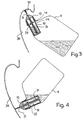
- the chamber 9 has an outlet in the form of a nozzle 21, which is preferably at an angle of approximately 40 degrees to the Bottle longitudinal axis 23 is directed upwards. This is caused, for example, by a corresponding inclination of the bottle neck. As FIG. 3 shows, this angle proves to be particularly expedient for cleaning the inner upper rinsing rim 37 of a toilet bowl 39.
- the chamber 19 is closed at the bottom by a closure 25.
- the riser pipe 31 extends from the nozzle 21 to close to the lower end of the chamber 19.
- the chamber 19 and the riser pipe expediently form a first part 22 which can be inserted into the bottle neck 15 or screwed in or screwed on.
- the closure 25 expediently forms a second part 24.
- These two parts 22, 24 can be produced, for example, by injection molding from plastic.
- FIGS. 3 to 5 show the use of the squeeze bottle when cleaning a toilet bowl.
- FIG. 3 shows, when the bottle of liquid is pressed, the riser pipe 31 is driven up and exits the nozzle 21.
- Most of the toilet bowl 39 can be treated with the bottle with an obliquely upward jet (FIG. 3).
- the dosage of the amount of liquid is determined by the volume of the chamber 19 under the inlet openings 20. If there are still any untreated areas in the lower part of the toilet bowl 39, the bottle can also be used with the jet directed downward (FIG. 4, 5).
Landscapes
- Physics & Mathematics (AREA)
- Fluid Mechanics (AREA)
- General Physics & Mathematics (AREA)
- Engineering & Computer Science (AREA)
- Ceramic Engineering (AREA)
- Mechanical Engineering (AREA)
- Containers And Packaging Bodies Having A Special Means To Remove Contents (AREA)
Applications Claiming Priority (2)
| Application Number | Priority Date | Filing Date | Title |
|---|---|---|---|
| CH204795 | 1995-07-12 | ||
| CH2047/95 | 1995-07-12 |
Publications (2)
| Publication Number | Publication Date |
|---|---|
| EP0753355A2 true EP0753355A2 (fr) | 1997-01-15 |
| EP0753355A3 EP0753355A3 (fr) | 1997-10-15 |
Family
ID=4224699
Family Applications (1)
| Application Number | Title | Priority Date | Filing Date |
|---|---|---|---|
| EP96810451A Withdrawn EP0753355A3 (fr) | 1995-07-12 | 1996-07-12 | Bouteille déformable, notamment pour nettoyer les toilettes |
Country Status (1)
| Country | Link |
|---|---|
| EP (1) | EP0753355A3 (fr) |
Cited By (3)
| Publication number | Priority date | Publication date | Assignee | Title |
|---|---|---|---|---|
| US6604642B1 (en) * | 2002-03-21 | 2003-08-12 | Charlotte Barruw | Bottle having an offset neck |
| NL1031135C2 (nl) * | 2006-02-13 | 2007-08-14 | Dispensing Technologies Bv | Doseerinrichting voor een fluïdum. |
| USD841471S1 (en) | 2017-02-24 | 2019-02-26 | S. C. Johnson & Son, Inc. | Bottle |
Families Citing this family (1)
| Publication number | Priority date | Publication date | Assignee | Title |
|---|---|---|---|---|
| USD845135S1 (en) | 2017-02-24 | 2019-04-09 | S. C. Johnson & Son, Inc. | Bottle neck with cap |
Family Cites Families (3)
| Publication number | Priority date | Publication date | Assignee | Title |
|---|---|---|---|---|
| GB1311086A (en) * | 1969-09-04 | 1973-03-21 | Beecham Group Ltd | Bottles |
| CH638114A5 (de) * | 1980-07-03 | 1983-09-15 | Duering Ag | Hand-quetschflasche zur erzeugung eines gerichteten fluessigkeitsstrahles. |
| DE9207892U1 (de) * | 1992-06-12 | 1992-08-27 | Hem GmbH, 4800 Bielefeld | Ausspritzverschluß für/an Quetschflaschen |
-
1996
- 1996-07-12 EP EP96810451A patent/EP0753355A3/fr not_active Withdrawn
Cited By (5)
| Publication number | Priority date | Publication date | Assignee | Title |
|---|---|---|---|---|
| US6604642B1 (en) * | 2002-03-21 | 2003-08-12 | Charlotte Barruw | Bottle having an offset neck |
| NL1031135C2 (nl) * | 2006-02-13 | 2007-08-14 | Dispensing Technologies Bv | Doseerinrichting voor een fluïdum. |
| WO2007094660A1 (fr) * | 2006-02-13 | 2007-08-23 | Dispensing Technologies B.V. | Dispositif de dosage pour fluide |
| CN101379374B (zh) * | 2006-02-13 | 2010-12-01 | 分配技术有限公司 | 用于流体的剂量分配装置 |
| USD841471S1 (en) | 2017-02-24 | 2019-02-26 | S. C. Johnson & Son, Inc. | Bottle |
Also Published As
| Publication number | Publication date |
|---|---|
| EP0753355A3 (fr) | 1997-10-15 |
Similar Documents
| Publication | Publication Date | Title |
|---|---|---|
| DE3121591C2 (de) | Hand-Quetschflasche, insbesondere zur Reinigung von WC-Schüsseln | |
| DE2946063A1 (de) | Flasche mit getrennten abteilungen | |
| EP0638276B1 (fr) | Distributeur de liquide | |
| DE1486422A1 (de) | Behaelter | |
| EP0875461B1 (fr) | Bouteille, en particulier pour le nettoyage des cuvettes de WC | |
| CH421383A (de) | Behälteraufsatz mit Bechern, insbesondere Flaschenaufsatz mit Dosierbechern | |
| EP0911616B1 (fr) | Bouteille, en particulier pour nettoyer des cuvettes de w.c. | |
| EP0753355A2 (fr) | Bouteille déformable, notamment pour nettoyer les toilettes | |
| WO1993025441A1 (fr) | Flacon en plastique pressable muni d'un dispositif de dosage et d'un bouchon gicleur | |
| DE946595C (de) | Trichter fuer Schankzwecke od. dgl. | |
| DE102022130554B4 (de) | Wiederverwendbarer und modular aufgebauter Spender für Fluide | |
| WO2003104106A1 (fr) | Recipient a plusieurs compartiments | |
| DE9310105U1 (de) | Dosierer für/an eine Reinigungsflüssigkeit beinhaltende Flaschen | |
| DE2141071A1 (de) | Tropf- oder giesseinsatz | |
| DE60303913T2 (de) | Verpackungseinheit zum Aufbewahren einer Flüssigkeit | |
| DE4422918B4 (de) | Vorrichtung zum dosierten Zuführen eines fließfähigen Zugabemittels in Spülwassersysteme o. dgl. | |
| DE9401797U1 (de) | Verschluß | |
| DE874647C (de) | Tropf- und/oder Giesseinsatz fuer Fluessigkeitsbehaelter, wie Flaschen od. dgl., auselastischem Material, wie Polyaethylen | |
| DE904004C (de) | Zusammenfaltbarer Giessbehaelter | |
| DE4333236A1 (de) | Verbindungseinrichtung für das Adaptieren einer Dosiervorrichtung an einen Behälter | |
| DE8625869U1 (de) | Dosierbehälter für Flüssigkeit aus elastischem Kunststoff | |
| CH674346A5 (en) | Device for dispensing predetermined liq. quantity from cask - contains metering chamber filled via ball valves when appts. is tilted, for emptying in upright position | |
| DE4425909A1 (de) | Behälter für fließfähige Körperpflegemittel, insbesondere Duschgele | |
| DE2024294A1 (de) | Ablageeinrichtung | |
| WO2001067921A1 (fr) | Brosse de nettoyage |
Legal Events
| Date | Code | Title | Description |
|---|---|---|---|
| PUAI | Public reference made under article 153(3) epc to a published international application that has entered the european phase |
Free format text: ORIGINAL CODE: 0009012 |
|
| AK | Designated contracting states |
Kind code of ref document: A2 Designated state(s): AT CH DE ES FR GB IT LI NL |
|
| PUAL | Search report despatched |
Free format text: ORIGINAL CODE: 0009013 |
|
| AK | Designated contracting states |
Kind code of ref document: A3 Designated state(s): AT CH DE ES FR GB IT LI NL |
|
| 17P | Request for examination filed |
Effective date: 19980406 |
|
| STAA | Information on the status of an ep patent application or granted ep patent |
Free format text: STATUS: THE APPLICATION HAS BEEN WITHDRAWN |
|
| 18W | Application withdrawn |
Withdrawal date: 20001011 |