EP0753367A2 - Tête d'outil utilisable dans des machines-outils - Google Patents
Tête d'outil utilisable dans des machines-outils Download PDFInfo
- Publication number
- EP0753367A2 EP0753367A2 EP96116560A EP96116560A EP0753367A2 EP 0753367 A2 EP0753367 A2 EP 0753367A2 EP 96116560 A EP96116560 A EP 96116560A EP 96116560 A EP96116560 A EP 96116560A EP 0753367 A2 EP0753367 A2 EP 0753367A2
- Authority
- EP
- European Patent Office
- Prior art keywords
- slide
- base body
- tool head
- head according
- tool
- Prior art date
- Legal status (The legal status is an assumption and is not a legal conclusion. Google has not performed a legal analysis and makes no representation as to the accuracy of the status listed.)
- Granted
Links
Images


Classifications
-
- B—PERFORMING OPERATIONS; TRANSPORTING
- B23—MACHINE TOOLS; METAL-WORKING NOT OTHERWISE PROVIDED FOR
- B23B—TURNING; BORING
- B23B29/00—Holders for non-rotary cutting tools; Boring bars or boring heads; Accessories for tool holders
- B23B29/03—Boring heads
- B23B29/034—Boring heads with tools moving radially, e.g. for making chamfers or undercuttings
- B23B29/03432—Boring heads with tools moving radially, e.g. for making chamfers or undercuttings radially adjustable during manufacturing
- B23B29/03446—Boring heads with tools moving radially, e.g. for making chamfers or undercuttings radially adjustable during manufacturing by means of inclined planes
-
- B—PERFORMING OPERATIONS; TRANSPORTING
- B23—MACHINE TOOLS; METAL-WORKING NOT OTHERWISE PROVIDED FOR
- B23B—TURNING; BORING
- B23B29/00—Holders for non-rotary cutting tools; Boring bars or boring heads; Accessories for tool holders
- B23B29/03—Boring heads
- B23B29/034—Boring heads with tools moving radially, e.g. for making chamfers or undercuttings
- B23B29/03432—Boring heads with tools moving radially, e.g. for making chamfers or undercuttings radially adjustable during manufacturing
- B23B29/03457—Boring heads with tools moving radially, e.g. for making chamfers or undercuttings radially adjustable during manufacturing by pivoting the tool carriers or by elastic deformation
-
- B—PERFORMING OPERATIONS; TRANSPORTING
- B23—MACHINE TOOLS; METAL-WORKING NOT OTHERWISE PROVIDED FOR
- B23B—TURNING; BORING
- B23B2229/00—Details of boring bars or boring heads
- B23B2229/16—Boring, facing or grooving heads with integral electric motor
-
- B—PERFORMING OPERATIONS; TRANSPORTING
- B23—MACHINE TOOLS; METAL-WORKING NOT OTHERWISE PROVIDED FOR
- B23B—TURNING; BORING
- B23B2270/00—Details of turning, boring or drilling machines, processes or tools not otherwise provided for
- B23B2270/48—Measuring or detecting
-
- Y—GENERAL TAGGING OF NEW TECHNOLOGICAL DEVELOPMENTS; GENERAL TAGGING OF CROSS-SECTIONAL TECHNOLOGIES SPANNING OVER SEVERAL SECTIONS OF THE IPC; TECHNICAL SUBJECTS COVERED BY FORMER USPC CROSS-REFERENCE ART COLLECTIONS [XRACs] AND DIGESTS
- Y10—TECHNICAL SUBJECTS COVERED BY FORMER USPC
- Y10T—TECHNICAL SUBJECTS COVERED BY FORMER US CLASSIFICATION
- Y10T408/00—Cutting by use of rotating axially moving tool
- Y10T408/83—Tool-support with means to move Tool relative to tool-support
- Y10T408/85—Tool-support with means to move Tool relative to tool-support to move radially
-
- Y—GENERAL TAGGING OF NEW TECHNOLOGICAL DEVELOPMENTS; GENERAL TAGGING OF CROSS-SECTIONAL TECHNOLOGIES SPANNING OVER SEVERAL SECTIONS OF THE IPC; TECHNICAL SUBJECTS COVERED BY FORMER USPC CROSS-REFERENCE ART COLLECTIONS [XRACs] AND DIGESTS
- Y10—TECHNICAL SUBJECTS COVERED BY FORMER USPC
- Y10T—TECHNICAL SUBJECTS COVERED BY FORMER US CLASSIFICATION
- Y10T408/00—Cutting by use of rotating axially moving tool
- Y10T408/83—Tool-support with means to move Tool relative to tool-support
- Y10T408/85—Tool-support with means to move Tool relative to tool-support to move radially
- Y10T408/858—Moving means including wedge, screw or cam
-
- Y—GENERAL TAGGING OF NEW TECHNOLOGICAL DEVELOPMENTS; GENERAL TAGGING OF CROSS-SECTIONAL TECHNOLOGIES SPANNING OVER SEVERAL SECTIONS OF THE IPC; TECHNICAL SUBJECTS COVERED BY FORMER USPC CROSS-REFERENCE ART COLLECTIONS [XRACs] AND DIGESTS
- Y10—TECHNICAL SUBJECTS COVERED BY FORMER USPC
- Y10T—TECHNICAL SUBJECTS COVERED BY FORMER US CLASSIFICATION
- Y10T408/00—Cutting by use of rotating axially moving tool
- Y10T408/83—Tool-support with means to move Tool relative to tool-support
- Y10T408/85—Tool-support with means to move Tool relative to tool-support to move radially
- Y10T408/858—Moving means including wedge, screw or cam
- Y10T408/8593—Wedge moving perpendicular to tool-axis
-
- Y—GENERAL TAGGING OF NEW TECHNOLOGICAL DEVELOPMENTS; GENERAL TAGGING OF CROSS-SECTIONAL TECHNOLOGIES SPANNING OVER SEVERAL SECTIONS OF THE IPC; TECHNICAL SUBJECTS COVERED BY FORMER USPC CROSS-REFERENCE ART COLLECTIONS [XRACs] AND DIGESTS
- Y10—TECHNICAL SUBJECTS COVERED BY FORMER USPC
- Y10T—TECHNICAL SUBJECTS COVERED BY FORMER US CLASSIFICATION
- Y10T408/00—Cutting by use of rotating axially moving tool
- Y10T408/83—Tool-support with means to move Tool relative to tool-support
- Y10T408/85—Tool-support with means to move Tool relative to tool-support to move radially
- Y10T408/858—Moving means including wedge, screw or cam
- Y10T408/8598—Screw extending perpendicular to tool-axis
Definitions
- the invention relates to a tool head for use in machine tools with a base body, a tool shaft projecting axially beyond the base body, which can be coupled with a rotating machine spindle, with at least one slide which can be adjusted transversely to the base body axis and has a tool holder projecting on the end face, with a measuring device for direct measurement of the Adjustment path of the slide relative to the base body, with a measuring electronics arranged in the base body and connected to the measuring device, with a preferably electric adjustment motor arranged in the base body, acting on the slide in the adjustment direction and with a power supply device for the measurement electronics and possibly the adjustment motor.
- the object of the invention is to develop a tool head of the type specified at the outset, which ensures a compact design and trouble-free operation.
- the measuring device has a plunger housing which is arranged in a coil housing which is fixed to the main body and engages in a pocket-like recess of the slide and a plunger-resistant rod-shaped magnet armature which extends through the pocket-like recess and the plunger in the direction of displacement of the slide and transversely to the axis of the motor housing.
- the measuring system working according to the moving coil principle has the advantage over the known capacitive measuring system that an absolute displacement measurement is possible without loss of data when the power is switched off and that the installation requires less stringent requirements.
- the magnet armature is expediently at one end an adjusting holder, which is screwed into a threaded bore aligned in the direction of displacement of the slide, is attached at the end in a projecting manner, while on its end opposite the adjusting holder it carries a guide pin which engages in a linear guide inside the slide.
- the adjustment holder can be fixed on the slide by an adjusting screw which is accessible from the outside in a predetermined displacement position of the slide.
- the coil housing which is preferably made of an antimagnetic material, has laterally projecting mounting tabs for attachment to the base body. It expediently has a round, closed coil space for receiving the moving coil, and is provided on the side facing the motor, preferably in the area between the two mounting tabs, with a recess which partially surrounds the motor housing on its circumference. The resulting mutual toothing between the coil housing and the motor housing enables a compact design of the tool head.
- the slide with its tool holder engages through an oblong face hole of the base body and outside the slot a radially sealed against the slide, moving with the slide ring disc, which is resiliently pressed against an arranged in a front annular groove of the base body, preferably designed as a quad ring elastomeric sealing ring that between the washer and base body a substantially constant over the circumference of the washer Gap with a width of 5 to 20 microns remains.
- the wall thickness of the ring disk is expediently adjustable by removing material from its surface facing the base body by setting the predetermined gap width, while the ring disk can be pressed against the sealing ring by a spring ring arranged in a circumferential groove on the slide side.
- the base body has a radially continuous, end-limit-free slide surface for the slide, and that on the side of the slide block Spacer is arranged between the base body and a cover part. The spacer also ensures that the back forces from the helical teeth of the adjustment mechanism for the slide can be absorbed and introduced into the base body.
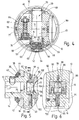
- the fine turret shown in the drawing consists essentially of a base body 10, an adjustable transverse to the axis of rotation 12 of the fine turret relative to the base body 10, a tool holder 14 for a cutting tool slider 16, a measuring device 18 for direct displacement measurement of the slider 16 relative to the base body 10 , an electrical acting on the slide in the direction of adjustment Adjusting motor 20, a power supply device 22 and a tool shaft 24 projecting axially beyond the base body 10 and which can be coupled to a machine spindle 26 of a machine tool 28.
- the slider 16 is arranged in the base body 10 in a continuous, end-limit-free guide groove 30 which is oriented transversely to the base body axis 12 and is delimited on the outside by a cover part 32 rigidly connected to the base body 10 at the end by means of spacers.
- the slide 16 engages through an elongated hole 34 of the cover part 32 to the outside and carries, outside the slot 34, an annular disk 38, which is sealed radially against the tool holder 14 via the sealing ring 36 and is moved with the slide and resiliently by means of the spring ring 40 can be pressed against a quad ring 44 arranged in an annular groove 42 of the cover part in such a way that an essentially constant gap with a width of 10 ⁇ m remains between the ring disc 38 and the cover part 32. This measure prevents the metallic ring disk 38 from rubbing against the metallic cover part 32 when the slide is moved.
- the adjusting motor 20 has an essentially cylindrical motor housing 45, which is arranged in a transverse recess in the base body 10 which runs transverse to the direction of displacement of the slide 16 and the base body axis 12 and intersects the base body axis 12 is.
- the axially projecting output shaft 48 is designed as a hexagon. It carries a cup-shaped output gear 50, the hexagon socket 52 of which is longer than the output shaft 48, so that a corresponding hexagon tool for manual adjustment of the output gearwheel can be inserted into the hexagon socket 52 from the outside when the screw plug 54 is removed.
- the output gear 50 overlaps the output-side end of the motor housing 45 and is supported there radially on the outside of a sleeve extension 58 receiving the relevant housing end via a slide bearing 60. Furthermore, the output gear 50 is mounted axially on the sleeve shoulder 58 with its inside of the pot via a roller bearing 62, while it is mounted on the outside of the pot with its hollow pin 63 having the hexagon socket 52 in a rotary bearing of a pot-shaped cover part 66 designed as a roller bearing 64.
- the adjusting motor 20 On its side opposite the output side, the adjusting motor 20 is axially clamped against the output-side sleeve extension 58 with a tensioning cover 68 and an elastomeric ring 70, the motor housing 45 being secured against rotation via the eccentric pins 72 arranged on the output side.
- the axially elastic clamping with torsional elasticity results in a soft starting of the motor, which can reduce starting current peaks. Taking into account the centrifugal force acting on the motor, this applies in particular when the center of gravity of the adjusting motor is towards the elastic ring 70 towards the axis of rotation 12 of the base body 10 is radially displaced.
- an eccentrically arranged adjusting mechanism for the slide is driven, which has a drive pinion 76 meshing with the ring gear 74 of the driven gear 50 and a threaded spindle 77 rigidly connected to it.
- a sliding block 78 with a helical toothing 80 is guided, which meshes with a complementary helical toothing 82 of a counterpart 84 arranged on the slide 16.
- the measuring device 18 has a plunger coil 86 fixed to the base body and a slide-proof rod-shaped magnet armature 88 which engages in the displacement direction in the plunger coil 86.
- the plunger coil 86 is arranged essentially centrally in the base body 10 in a coil housing 90 fixed to the base body, which engages from the motor side together with the plunger coil in a pocket-like recess 92 of the slide.
- the magnet armature 88 is fastened at one end to an adjustment holder 94 which is screwed into a threaded bore 95 oriented in the direction of displacement of the slide 16, while at its end opposite the adjustment holder 94 it has a guide pin which engages in a linear guide (bore) 96 within the slide 16 98 wears.
- the adjustment holder 94 is accessible from the outside by means of an adjusting screw which is accessible in a predetermined displacement position of the slide 100 definable on the slider 16.
- the coil housing is provided with laterally projecting mounting tabs 102 and, on its side opposite the coil space 104, has a recess 106 arranged in the area between the two mounting tabs 102 and partially encompassing the motor housing 45 on its circumference.
- the base body 10 is surrounded on its circumference by a jacket ring 108 made of metal or plastic, in which windows 110 for infrared transceivers 112 are arranged, which are distributed over the circumference at equal angular intervals.
- the transceivers ensure wireless data exchange between the tool head and an external, computer-aided remote control device. The data can also be exchanged galvanically via the interface 114 for adjustment purposes, for example.
- the tool shank 24 for connection to the machine spindle 26 is axially fastened to the base body 10 in a shank receptacle 117 with a single central screw 116.
- the eccentrically arranged dowel pins 118 ensure rotation and torque transmission.
- annular coil housing 120 On the side of the tool shaft 24, an annular coil housing 120 is additionally arranged, which is fastened together with the tool shaft 24 via the radially projecting collar 122 with the central screw 116 to the base body.
- the anti-rotation device of the Coil housing 120 takes place via the drive bolts 124, which are designed as countersunk screws and engage with their shafts in corresponding bores in the base body.
- the coil housing 120 there is a secondary coil embedded in a mechanically resilient casting compound made of plastic or synthetic resin with associated stabilization electronics, which is part of an inductive transmission path of the power supply device 22 and provides the power supply for the adjusting motor 20 and the electronic circuits contained in the tool head.
- a mechanically resilient casting compound made of plastic or synthetic resin with associated stabilization electronics, which is part of an inductive transmission path of the power supply device 22 and provides the power supply for the adjusting motor 20 and the electronic circuits contained in the tool head.
- the induction path for bidirectional data transmission, in that the data signals are optionally modulated onto the induction current in both directions.
- the primary coil of the inductive transmission path is arranged in a stator-side coil housing 126, which engages radially outside the tool shaft 24 in the free space between the end face of the machine spindle 26 and the end face of the tool head-side coil housing 120.
- the stator-side coil housing 126 is arranged on a stator-fixed holder 128 both in its distance from the tool head-side coil housing 120 and in its rotational position about an axis parallel to the axis of rotation 12.
- the holder 128 with the bobbin case 126 can also be retrofitted to an existing machine tool.
- the stator-side coil housing 126 extends only over a partial circumference of the tool shank and leaves most of the shank circumference free for the access of a tool gripper 130 for the automatic tool change.
- the tool head on the gripper groove 132 is gripped by the tool gripper 130 from the side opposite the stator-side coil housing 126 and axially displaced relative to the machine spindle 26 when the tool coupling is released.
- the coupling of the tool head to the machine spindle 26 takes place via a tensioning mechanism 136 which can be actuated on the machine side via the pull rod 134, which engages in the cavity 138 of the tool shaft 24 from the machine side and couples the tool head to the machine spindle 26 with the production of a plane surface tensioning and a radial tensioning.
Landscapes
- Engineering & Computer Science (AREA)
- Mechanical Engineering (AREA)
- Automatic Tool Replacement In Machine Tools (AREA)
- Jigs For Machine Tools (AREA)
- Connection Of Motors, Electrical Generators, Mechanical Devices, And The Like (AREA)
- Turning (AREA)
- Cutting Tools, Boring Holders, And Turrets (AREA)
- Machine Tool Units (AREA)
- Portable Nailing Machines And Staplers (AREA)
- Measurement Of Length, Angles, Or The Like Using Electric Or Magnetic Means (AREA)
Applications Claiming Priority (3)
| Application Number | Priority Date | Filing Date | Title |
|---|---|---|---|
| DE4330822A DE4330822A1 (de) | 1993-09-13 | 1993-09-13 | Werkzeugkopf für den Einsatz in Werkzeugmaschinen |
| DE4330822 | 1993-09-13 | ||
| EP94923723A EP0719195B1 (fr) | 1993-09-13 | 1994-07-12 | Tete d'outil utilisable dans des machines-outils |
Related Parent Applications (2)
| Application Number | Title | Priority Date | Filing Date |
|---|---|---|---|
| EP94923723A Division EP0719195B1 (fr) | 1993-09-13 | 1994-07-12 | Tete d'outil utilisable dans des machines-outils |
| EP94923723.4 Division | 1994-07-12 |
Publications (3)
| Publication Number | Publication Date |
|---|---|
| EP0753367A2 true EP0753367A2 (fr) | 1997-01-15 |
| EP0753367A3 EP0753367A3 (fr) | 1997-07-23 |
| EP0753367B1 EP0753367B1 (fr) | 1999-12-08 |
Family
ID=6497436
Family Applications (2)
| Application Number | Title | Priority Date | Filing Date |
|---|---|---|---|
| EP94923723A Expired - Lifetime EP0719195B1 (fr) | 1993-09-13 | 1994-07-12 | Tete d'outil utilisable dans des machines-outils |
| EP96116560A Expired - Lifetime EP0753367B1 (fr) | 1993-09-13 | 1994-07-12 | Tête d'outil utilisable dans des machines-outils |
Family Applications Before (1)
| Application Number | Title | Priority Date | Filing Date |
|---|---|---|---|
| EP94923723A Expired - Lifetime EP0719195B1 (fr) | 1993-09-13 | 1994-07-12 | Tete d'outil utilisable dans des machines-outils |
Country Status (10)
| Country | Link |
|---|---|
| US (1) | US5807037A (fr) |
| EP (2) | EP0719195B1 (fr) |
| JP (1) | JP3380557B2 (fr) |
| CN (1) | CN1047971C (fr) |
| AT (2) | ATE153262T1 (fr) |
| DE (3) | DE4330822A1 (fr) |
| DK (2) | DK0719195T3 (fr) |
| ES (2) | ES2140777T3 (fr) |
| SG (1) | SG47644A1 (fr) |
| WO (1) | WO1995007785A1 (fr) |
Cited By (1)
| Publication number | Priority date | Publication date | Assignee | Title |
|---|---|---|---|---|
| WO2021047940A1 (fr) * | 2019-09-11 | 2021-03-18 | Blum-Novotest Gmbh | Tête de réglage de lame d'outil et son procédé de fonctionnement et de correction de l'usure de la lame d'outil |
Families Citing this family (15)
| Publication number | Priority date | Publication date | Assignee | Title |
|---|---|---|---|---|
| DE19509524C2 (de) * | 1995-03-20 | 1999-01-14 | Mapal Fab Praezision | Spanendes Werkzeug zur Bohrungsfeinbearbeitung |
| CZ290502B6 (cs) * | 1996-05-03 | 2002-08-14 | Komet Präzisionswerkzeuge Robert Breuning Gmbh | Nástrojová hlava pro obráběcí stroje |
| DE19813615C2 (de) * | 1998-03-27 | 2001-02-15 | Widia Gmbh | Werkzeugkopf |
| US6186707B1 (en) | 1999-09-10 | 2001-02-13 | The Boeing Company | Apparatus for locating holes to be drilled in post cure composite structures and associated method |
| ES2169997B1 (es) * | 2000-05-16 | 2004-02-16 | Danobat | Maquina rectificadora con cabezal portamuela con reductor de accionamiento armonico. |
| KR100559119B1 (ko) * | 2004-03-19 | 2006-03-14 | (주)거상테크놀로지 | 싱크대 장착형 식기 세척장치 |
| GB0413986D0 (en) † | 2004-06-23 | 2004-07-28 | Rigibore Ltd | Cutting tool adjustment system |
| DE102005043851A1 (de) | 2005-09-13 | 2007-03-22 | Komet Group Holding Gmbh | Werkzeugkopf mit Verstellmotor |
| ATE492364T1 (de) * | 2008-02-26 | 2011-01-15 | Comau Spa | Bearbeitungseinheit mit einer regelungsvorrichtung zum einstellen des werkzeuges und eine drahtlose steuerung für die regelungsvorrichtung |
| DE102009017094A1 (de) * | 2009-04-15 | 2010-10-21 | Komet Group Gmbh | Schneidwerkzeugeinstellsystem |
| DE102010002557A1 (de) * | 2010-03-03 | 2011-09-08 | Sandvik Intellectual Property Ab | Zerspanungswerkzeug mit spielfreier Feinstverstellung |
| DE102010029288A1 (de) * | 2010-05-25 | 2011-12-01 | Komet Group Gmbh | Werkzeugmaschine für Drehbearbeitung |
| DE102011080701A1 (de) | 2011-08-09 | 2013-02-14 | Komet Group Gmbh | Werkzeugkopf für eine Werkzeugmaschine |
| JP6902691B2 (ja) * | 2016-11-10 | 2021-07-14 | エヌティーエンジニアリング株式会社 | 位置補正機能付き作業機械。 |
| IT201800004836A1 (it) * | 2018-04-24 | 2019-10-24 | Piattaforma a sfacciare con elevate prestazioni |
Citations (1)
| Publication number | Priority date | Publication date | Assignee | Title |
|---|---|---|---|---|
| WO1991003345A1 (fr) | 1989-09-09 | 1991-03-21 | Komet Stahlhalter- Und Werkzeugfabrik Robert Breuning Gmbh | Tete d'outil pour machines-outils |
Family Cites Families (17)
| Publication number | Priority date | Publication date | Assignee | Title |
|---|---|---|---|---|
| DE284176C (de) * | 1914-05-01 | 1915-05-04 | Basf Ag | Verfahren zur Herstellung von Wasserstoff durch katalytische Umsetzung von Wasserdampf mit Kohlenoxyd |
| CH351015A (fr) * | 1958-12-30 | 1960-12-31 | Genevoise Instr Physique | Equipement de machine-outil à broche porte-outil rotative |
| US3153354A (en) * | 1962-12-26 | 1964-10-20 | Joseph J Prince Jr | Adjustable tool head attachment |
| US3198037A (en) * | 1964-05-07 | 1965-08-03 | Valeron Corp | Turret nose boring bar |
| US3533195A (en) * | 1968-04-22 | 1970-10-13 | Rockwell Mfg Co | Jig grinder head |
| US3526159A (en) * | 1968-05-15 | 1970-09-01 | Heald Machine Co | Machine tool |
| FR2033145A5 (fr) * | 1969-03-04 | 1970-11-27 | Olivetti & Co Spa | |
| DE2728975C2 (de) * | 1977-06-28 | 1981-10-08 | Komet Stahlhalter- Und Werkzeugfabrik Robert Breuning Gmbh, 7122 Besigheim | Plan- und Ausdrehkopf |
| DE2935178A1 (de) * | 1979-08-31 | 1981-03-19 | Heyligenstaedt & Co, Werkzeugmaschinenfabrik Gmbh, 6300 Giessen | Fuehler fuer eine kopierwerkzeugmaschine |
| GB2115929B (en) * | 1982-02-17 | 1985-11-27 | Standard Telephones Cables Ltd | Inductive position transducer |
| FR2570008B2 (fr) * | 1984-04-24 | 1988-08-05 | Pfalzgraf Emile | Tete d'alesage |
| DE3416217A1 (de) * | 1984-05-02 | 1985-11-07 | Unima Maschinenbau Gmbh, 6603 Sulzbach | Spindeleinheit fuer eine werkzeugmaschine |
| JPS6144501A (ja) * | 1984-08-06 | 1986-03-04 | Hideo Mizoguchi | フェーシングヘッド |
| US4847975A (en) * | 1987-05-11 | 1989-07-18 | Amca International Corporation | Boring tool for machine tool |
| DE3726276A1 (de) * | 1987-08-07 | 1989-02-23 | Samson Ag | Einrichtung zum feinverstellen der werkzeugschneide eines umlaufenden radialstellkopfes |
| FR2645055A1 (fr) * | 1989-03-31 | 1990-10-05 | Gamet Precision | Appareil a aleser et surfacer, a avance et recul automatiques |
| DE3942219C1 (en) * | 1989-12-21 | 1991-02-21 | Bernhard Dr.-Ing. 4782 Erwitte De Juergenhake | Crimped connection quality measurement method - measuring distance positionally fixed tool or press base and active tool or press head |
-
1993
- 1993-09-13 DE DE4330822A patent/DE4330822A1/de not_active Ceased
-
1994
- 1994-07-12 CN CN94193362A patent/CN1047971C/zh not_active Expired - Fee Related
- 1994-07-12 WO PCT/EP1994/002273 patent/WO1995007785A1/fr not_active Ceased
- 1994-07-12 DK DK94923723.4T patent/DK0719195T3/da active
- 1994-07-12 AT AT94923723T patent/ATE153262T1/de not_active IP Right Cessation
- 1994-07-12 US US08/615,302 patent/US5807037A/en not_active Expired - Lifetime
- 1994-07-12 DK DK96116560T patent/DK0753367T3/da active
- 1994-07-12 ES ES96116560T patent/ES2140777T3/es not_active Expired - Lifetime
- 1994-07-12 AT AT96116560T patent/ATE187373T1/de not_active IP Right Cessation
- 1994-07-12 EP EP94923723A patent/EP0719195B1/fr not_active Expired - Lifetime
- 1994-07-12 DE DE59402847T patent/DE59402847D1/de not_active Expired - Lifetime
- 1994-07-12 ES ES94923723T patent/ES2103602T3/es not_active Expired - Lifetime
- 1994-07-12 SG SG1996003351A patent/SG47644A1/en unknown
- 1994-07-12 EP EP96116560A patent/EP0753367B1/fr not_active Expired - Lifetime
- 1994-07-12 DE DE59408994T patent/DE59408994D1/de not_active Expired - Lifetime
- 1994-07-12 JP JP50892795A patent/JP3380557B2/ja not_active Expired - Fee Related
Patent Citations (1)
| Publication number | Priority date | Publication date | Assignee | Title |
|---|---|---|---|---|
| WO1991003345A1 (fr) | 1989-09-09 | 1991-03-21 | Komet Stahlhalter- Und Werkzeugfabrik Robert Breuning Gmbh | Tete d'outil pour machines-outils |
Cited By (1)
| Publication number | Priority date | Publication date | Assignee | Title |
|---|---|---|---|---|
| WO2021047940A1 (fr) * | 2019-09-11 | 2021-03-18 | Blum-Novotest Gmbh | Tête de réglage de lame d'outil et son procédé de fonctionnement et de correction de l'usure de la lame d'outil |
Also Published As
| Publication number | Publication date |
|---|---|
| JPH09502398A (ja) | 1997-03-11 |
| DE59408994D1 (de) | 2000-01-13 |
| EP0719195B1 (fr) | 1997-05-21 |
| CN1047971C (zh) | 2000-01-05 |
| SG47644A1 (en) | 1998-04-17 |
| EP0753367A3 (fr) | 1997-07-23 |
| ES2103602T3 (es) | 1997-09-16 |
| DK0719195T3 (da) | 1997-12-15 |
| ATE153262T1 (de) | 1997-06-15 |
| DE4330822A1 (de) | 1995-03-16 |
| DE59402847D1 (de) | 1997-06-26 |
| EP0753367B1 (fr) | 1999-12-08 |
| US5807037A (en) | 1998-09-15 |
| ES2140777T3 (es) | 2000-03-01 |
| WO1995007785A1 (fr) | 1995-03-23 |
| DK0753367T3 (da) | 2000-06-13 |
| ATE187373T1 (de) | 1999-12-15 |
| JP3380557B2 (ja) | 2003-02-24 |
| CN1130886A (zh) | 1996-09-11 |
| EP0719195A1 (fr) | 1996-07-03 |
Similar Documents
| Publication | Publication Date | Title |
|---|---|---|
| EP0719195B1 (fr) | Tete d'outil utilisable dans des machines-outils | |
| EP1221350B1 (fr) | Tête d'usinage pour l'utilisation avec une machine outil | |
| EP0491724A1 (fr) | Tete d'outil pour machines-outils. | |
| EP1190798B1 (fr) | Tête d'usinage avec porte-outil ajustable | |
| EP2493647B1 (fr) | Outil de tournage précis | |
| EP0461357A2 (fr) | Tourelle révolver porte outil | |
| EP0719199B1 (fr) | Tete d'outil a alimentation exterieure en courant | |
| DE19813615C2 (de) | Werkzeugkopf | |
| WO2001043904A1 (fr) | Mecanisme d'entrainement d'outil destine a des machines-outils | |
| EP0297150A1 (fr) | Détecteur de position pour la part mobile d'un servomoteur actionné par fluide | |
| DE3111519A1 (de) | Mikrometer | |
| DE4204644A1 (de) | Vorrichtung zur einstellung der eingespannten laenge eines bohrers in einem bohrkopf | |
| DE29724877U1 (de) | Werkzeugkopf für den Einsatz in Werkzeugmaschinen | |
| DE2946271A1 (de) | Messkopf fuer eine messmaschine | |
| DE2608930C3 (de) | Plan- und Ausdrehkopf | |
| EP0756920B1 (fr) | Dispositif pour fraiser des rainures | |
| DE1752539A1 (de) | Einrichtung zur Erzeugung translatorischer Bewegungen,insbesondere fuer Werkzeugmaschinen | |
| JPS61230833A (ja) | 工作機械テーブル上で工作物をセンタリングするための装置 | |
| DE3440837A1 (de) | Zusammengesetzte kleinmodulzahnradwaelzfraeser mit reguliertem profil | |
| DE8234896U1 (de) | Drucksensor | |
| DE4323752A1 (de) | Wegsensor | |
| DD252677A5 (de) | Einrichtung fuer amplitudenmessungen | |
| DE3314769A1 (de) | Teilkopf | |
| DE3644954A1 (de) | Feinstverstellkopf fuer eine werkzeugmaschine, insbesondere eine bohrmaschine oder dgl. | |
| DE2344928A1 (de) | Langdrehmaschine zur herstellung von einzeldrehteilen aus stangenmaterial |
Legal Events
| Date | Code | Title | Description |
|---|---|---|---|
| PUAI | Public reference made under article 153(3) epc to a published international application that has entered the european phase |
Free format text: ORIGINAL CODE: 0009012 |
|
| AC | Divisional application: reference to earlier application |
Ref document number: 719195 Country of ref document: EP |
|
| AK | Designated contracting states |
Kind code of ref document: A2 Designated state(s): AT BE CH DE DK ES FR GB IT LI NL SE |
|
| PUAL | Search report despatched |
Free format text: ORIGINAL CODE: 0009013 |
|
| AK | Designated contracting states |
Kind code of ref document: A3 Designated state(s): AT BE CH DE DK ES FR GB IT LI NL SE |
|
| 17P | Request for examination filed |
Effective date: 19971011 |
|
| GRAG | Despatch of communication of intention to grant |
Free format text: ORIGINAL CODE: EPIDOS AGRA |
|
| 17Q | First examination report despatched |
Effective date: 19981218 |
|
| GRAG | Despatch of communication of intention to grant |
Free format text: ORIGINAL CODE: EPIDOS AGRA |
|
| GRAG | Despatch of communication of intention to grant |
Free format text: ORIGINAL CODE: EPIDOS AGRA |
|
| GRAH | Despatch of communication of intention to grant a patent |
Free format text: ORIGINAL CODE: EPIDOS IGRA |
|
| GRAH | Despatch of communication of intention to grant a patent |
Free format text: ORIGINAL CODE: EPIDOS IGRA |
|
| GRAA | (expected) grant |
Free format text: ORIGINAL CODE: 0009210 |
|
| AC | Divisional application: reference to earlier application |
Ref document number: 719195 Country of ref document: EP |
|
| AK | Designated contracting states |
Kind code of ref document: B1 Designated state(s): AT BE CH DE DK ES FR GB IT LI NL SE |
|
| REF | Corresponds to: |
Ref document number: 187373 Country of ref document: AT Date of ref document: 19991215 Kind code of ref document: T |
|
| REG | Reference to a national code |
Ref country code: CH Ref legal event code: EP |
|
| REF | Corresponds to: |
Ref document number: 59408994 Country of ref document: DE Date of ref document: 20000113 |
|
| GBT | Gb: translation of ep patent filed (gb section 77(6)(a)/1977) |
Effective date: 20000113 |
|
| ET | Fr: translation filed | ||
| ITF | It: translation for a ep patent filed | ||
| REG | Reference to a national code |
Ref country code: ES Ref legal event code: FG2A Ref document number: 2140777 Country of ref document: ES Kind code of ref document: T3 |
|
| REG | Reference to a national code |
Ref country code: DK Ref legal event code: T3 |
|
| PLBE | No opposition filed within time limit |
Free format text: ORIGINAL CODE: 0009261 |
|
| STAA | Information on the status of an ep patent application or granted ep patent |
Free format text: STATUS: NO OPPOSITION FILED WITHIN TIME LIMIT |
|
| 26N | No opposition filed | ||
| REG | Reference to a national code |
Ref country code: GB Ref legal event code: IF02 |
|
| PGFP | Annual fee paid to national office [announced via postgrant information from national office to epo] |
Ref country code: AT Payment date: 20030605 Year of fee payment: 10 |
|
| PGFP | Annual fee paid to national office [announced via postgrant information from national office to epo] |
Ref country code: DK Payment date: 20030610 Year of fee payment: 10 |
|
| PGFP | Annual fee paid to national office [announced via postgrant information from national office to epo] |
Ref country code: CH Payment date: 20030613 Year of fee payment: 10 |
|
| PGFP | Annual fee paid to national office [announced via postgrant information from national office to epo] |
Ref country code: BE Payment date: 20030710 Year of fee payment: 10 |
|
| PG25 | Lapsed in a contracting state [announced via postgrant information from national office to epo] |
Ref country code: AT Free format text: LAPSE BECAUSE OF NON-PAYMENT OF DUE FEES Effective date: 20040712 |
|
| PG25 | Lapsed in a contracting state [announced via postgrant information from national office to epo] |
Ref country code: LI Free format text: LAPSE BECAUSE OF NON-PAYMENT OF DUE FEES Effective date: 20040731 Ref country code: CH Free format text: LAPSE BECAUSE OF NON-PAYMENT OF DUE FEES Effective date: 20040731 Ref country code: BE Free format text: LAPSE BECAUSE OF NON-PAYMENT OF DUE FEES Effective date: 20040731 |
|
| PG25 | Lapsed in a contracting state [announced via postgrant information from national office to epo] |
Ref country code: DK Free format text: LAPSE BECAUSE OF NON-PAYMENT OF DUE FEES Effective date: 20040802 |
|
| BERE | Be: lapsed |
Owner name: *KOMET PRAZISIONSWERKZEUGE ROBERT BREUNING G.M.B.H Effective date: 20040731 |
|
| REG | Reference to a national code |
Ref country code: DK Ref legal event code: EBP |
|
| REG | Reference to a national code |
Ref country code: CH Ref legal event code: PL |
|
| BERE | Be: lapsed |
Owner name: *KOMET PRAZISIONSWERKZEUGE ROBERT BREUNING G.M.B.H Effective date: 20040731 |
|
| NLT1 | Nl: modifications of names registered in virtue of documents presented to the patent office pursuant to art. 16 a, paragraph 1 |
Owner name: KOMET GROUP HOLDING GMBH Owner name: KOMET GROUP GMBH |
|
| REG | Reference to a national code |
Ref country code: FR Ref legal event code: CD |
|
| PGFP | Annual fee paid to national office [announced via postgrant information from national office to epo] |
Ref country code: NL Payment date: 20100714 Year of fee payment: 17 Ref country code: ES Payment date: 20100727 Year of fee payment: 17 |
|
| PGFP | Annual fee paid to national office [announced via postgrant information from national office to epo] |
Ref country code: SE Payment date: 20100715 Year of fee payment: 17 Ref country code: IT Payment date: 20100726 Year of fee payment: 17 Ref country code: FR Payment date: 20100805 Year of fee payment: 17 |
|
| REG | Reference to a national code |
Ref country code: NL Ref legal event code: V1 Effective date: 20120201 |
|
| REG | Reference to a national code |
Ref country code: SE Ref legal event code: EUG |
|
| REG | Reference to a national code |
Ref country code: FR Ref legal event code: ST Effective date: 20120330 |
|
| PG25 | Lapsed in a contracting state [announced via postgrant information from national office to epo] |
Ref country code: FR Free format text: LAPSE BECAUSE OF NON-PAYMENT OF DUE FEES Effective date: 20110801 |
|
| PG25 | Lapsed in a contracting state [announced via postgrant information from national office to epo] |
Ref country code: IT Free format text: LAPSE BECAUSE OF NON-PAYMENT OF DUE FEES Effective date: 20110712 Ref country code: NL Free format text: LAPSE BECAUSE OF NON-PAYMENT OF DUE FEES Effective date: 20120201 |
|
| PGFP | Annual fee paid to national office [announced via postgrant information from national office to epo] |
Ref country code: GB Payment date: 20120719 Year of fee payment: 19 |
|
| REG | Reference to a national code |
Ref country code: ES Ref legal event code: FD2A Effective date: 20121207 |
|
| PG25 | Lapsed in a contracting state [announced via postgrant information from national office to epo] |
Ref country code: ES Free format text: LAPSE BECAUSE OF NON-PAYMENT OF DUE FEES Effective date: 20110713 |
|
| PG25 | Lapsed in a contracting state [announced via postgrant information from national office to epo] |
Ref country code: SE Free format text: LAPSE BECAUSE OF NON-PAYMENT OF DUE FEES Effective date: 20110713 |
|
| PGFP | Annual fee paid to national office [announced via postgrant information from national office to epo] |
Ref country code: DE Payment date: 20130724 Year of fee payment: 20 |
|
| GBPC | Gb: european patent ceased through non-payment of renewal fee |
Effective date: 20130712 |
|
| PG25 | Lapsed in a contracting state [announced via postgrant information from national office to epo] |
Ref country code: GB Free format text: LAPSE BECAUSE OF NON-PAYMENT OF DUE FEES Effective date: 20130712 |
|
| REG | Reference to a national code |
Ref country code: DE Ref legal event code: R071 Ref document number: 59408994 Country of ref document: DE |
|
| PG25 | Lapsed in a contracting state [announced via postgrant information from national office to epo] |
Ref country code: DE Free format text: LAPSE BECAUSE OF EXPIRATION OF PROTECTION Effective date: 20140715 |