EP0753405B1 - Mehrmotorenantrieb für eine Druckmaschine - Google Patents
Mehrmotorenantrieb für eine Druckmaschine Download PDFInfo
- Publication number
- EP0753405B1 EP0753405B1 EP96109627A EP96109627A EP0753405B1 EP 0753405 B1 EP0753405 B1 EP 0753405B1 EP 96109627 A EP96109627 A EP 96109627A EP 96109627 A EP96109627 A EP 96109627A EP 0753405 B1 EP0753405 B1 EP 0753405B1
- Authority
- EP
- European Patent Office
- Prior art keywords
- drive
- cylinder
- drives
- cylinders
- motors
- Prior art date
- Legal status (The legal status is an assumption and is not a legal conclusion. Google has not performed a legal analysis and makes no representation as to the accuracy of the status listed.)
- Expired - Lifetime
Links
- 238000007639 printing Methods 0.000 title claims abstract description 25
- 238000012423 maintenance Methods 0.000 claims 1
- 230000001360 synchronised effect Effects 0.000 abstract description 4
- 230000000712 assembly Effects 0.000 description 10
- 238000000429 assembly Methods 0.000 description 10
- 238000012546 transfer Methods 0.000 description 4
- 230000008878 coupling Effects 0.000 description 3
- 238000010168 coupling process Methods 0.000 description 3
- 238000005859 coupling reaction Methods 0.000 description 3
- 238000007645 offset printing Methods 0.000 description 3
- 238000010276 construction Methods 0.000 description 2
- 230000006378 damage Effects 0.000 description 2
- 238000000034 method Methods 0.000 description 2
- 230000005540 biological transmission Effects 0.000 description 1
- 239000003990 capacitor Substances 0.000 description 1
- 230000001419 dependent effect Effects 0.000 description 1
- 238000011161 development Methods 0.000 description 1
- 230000018109 developmental process Effects 0.000 description 1
- 230000000694 effects Effects 0.000 description 1
- ZINJLDJMHCUBIP-UHFFFAOYSA-N ethametsulfuron-methyl Chemical compound CCOC1=NC(NC)=NC(NC(=O)NS(=O)(=O)C=2C(=CC=CC=2)C(=O)OC)=N1 ZINJLDJMHCUBIP-UHFFFAOYSA-N 0.000 description 1
- 238000012545 processing Methods 0.000 description 1
- 230000001105 regulatory effect Effects 0.000 description 1
- 238000012549 training Methods 0.000 description 1
Images

Classifications
-
- B—PERFORMING OPERATIONS; TRANSPORTING
- B41—PRINTING; LINING MACHINES; TYPEWRITERS; STAMPS
- B41F—PRINTING MACHINES OR PRESSES
- B41F13/00—Common details of rotary presses or machines
- B41F13/004—Electric or hydraulic features of drives
- B41F13/0045—Electric driving devices
-
- B—PERFORMING OPERATIONS; TRANSPORTING
- B41—PRINTING; LINING MACHINES; TYPEWRITERS; STAMPS
- B41P—INDEXING SCHEME RELATING TO PRINTING, LINING MACHINES, TYPEWRITERS, AND TO STAMPS
- B41P2213/00—Arrangements for actuating or driving printing presses; Auxiliary devices or processes
- B41P2213/70—Driving devices associated with particular installations or situations
- B41P2213/73—Driving devices for multicolour presses
- B41P2213/734—Driving devices for multicolour presses each printing unit being driven by its own electric motor, i.e. electric shaft
Definitions
- the invention relates to a multi-motor drive for a printing press according to the Preamble of claim 1.
- DE 4 322 744 A1 describes an electrical drive system for a printing press known, in which it is provided in particular, the cylinders with one motor each to be provided and synchronized with each other via a corresponding control to drive.
- angular position sensors are arranged directly on the cylinders, their signals from a common control to a corresponding rotation-synchronous run of the individual cylinders can be evaluated. Because with the rotation of a cylinder However, the load moment fluctuates greatly, and the drive quality is correspondingly high To make demands. On the one hand, the angular position must be over a cylinder revolution be guaranteed constantly, furthermore the cylinder must be in a predetermined Speed range to be driven.
- DE 4 202 722 A1 describes a safety device for regulation or control known from drive units of a printing press, in which the cylinders are individual Have drives.
- a mechanical coupling is provided, which is designed such that the cylinder does not exceed this predetermined dimension can be rotated relative to each other.
- the Corresponding coupling parts no contact with each other on this is only then Case, if the above-mentioned and leading to a destruction of a relative rotation specified dimension is present.
- the cylinders are synchronously synchronized achieve, but must also be relatively expensive drives for the individual Aggregates or cylinders are used.
- EP 0 355 442 B1 describes a method and a device for reducing the Torque load on a system driven by an electric motor, known in particular a printing press.
- This system is controlled of the drive motor in such a way, so the changes in the load torque on a be kept approximately constant value. This means that the speed of a such a printing machine is no longer a constant size, so that such
- the drive principle can only be transferred to a machine in a very complex manner the cylinders and / or individual assemblies are each provided with an individual drive.
- the object of the present invention is therefore a multi-motor drive for a To expand printing machine in such a way that with given requirements regarding the synchronism of the individually driven cylinders and / or assemblies of the Costs with regard to the drives to be used can be significantly reduced. Furthermore, the system to be created should also provide security with regard to the failure electrical and / or other drive components.
- each individually driven cylinder and / or Module is provided with two drives.
- the first drive turns on Basic moment initiated in the cylinder and / or assembly, that is Drive torque, which the cylinder or the assembly averages at one revolution needed.
- the second drive assigned to this cylinder or assembly is According to the invention designed such that this is only such a dynamic with respect to the remaining drive torque, which during a cylinder or. Compensate module rotation occurring short-term load moments.
- highly dynamic drive which is preferably brushless DC motor is formed, causes.
- the basic torque in the cylinder or Module feeding first drive with less dynamics via a gear (Reduction gear) is connected to the cylinder or the assembly.
- This Drive can advantageously be a particularly inexpensive Three-phase motor, especially with a calculated field model.
- the second, highly dynamic and preferably designed as a brushless DC motor The drive is then directly or via a torsionally rigid and play-free gear with the pin of the cylinder or a pin of a cylinder of the assembly of the printing press connected.
- the drive concept according to the invention results in a number of advantages, wherein the cost advantage when implementing a single or group drive despite of the two drives to be provided for each cylinder or assembly already above has been explained.
- Another advantage of the invention is that in the event of failure
- the highly dynamic and the briefly fluctuating Torque situation designed drive this cylinder or the assembly on the second drive can be shut down in a defined manner to a standstill.
- the other cylinders or assemblies follow the time behavior of this cylinder or this assembly.
- Even the failure of the basic torque in the cylinder or the Module feeding drive is capable of those indicated at the beginning of the description help to avoid mechanical collisions.
- the shutdown takes place of the cylinder or the assembly above the highly dynamic drive, which is not a problem represents, since the drives available today can be temporarily overloaded.
- both drives of a cylinder or an assembly fail, that is provided according to the invention that the position transmitter signal of this cylinder or this module is used as the position setpoint for all other units. In this case, this cylinder or assembly will expire by Standstill, with all other cylinders or assemblies angularly synchronized follow the leading axis.
- the failure of the supply voltage can also be caused by the drive system according to the invention can be collected, in which here the converter for the drives, for example, via a DC link are connected. The individual drives are then ramped to a standstill shutdown, which is dimensioned such that at any time by the When braking energy is fed back, the full DC voltage is still available.
- the embodiment described below describes the inventive Drive solution based on a group drive.
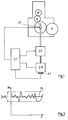
- 1 is here about two Drives 2.1 and 2.11 of the cylinder 1.1 leading the sheet to be printed on Printing unit driven.
- the assembly of the driven cylinder 1.1, that is corresponding printing unit of the sheetfed offset printing press also has one from the cylinder 1.1 driven transfer cylinder T, a blanket cylinder G and a plate cylinder P.
- These cylinders mentioned here are not one continuous wheel train shown connected.
- the drives 2.1 and 2.11 are in operative connection with a drive control 5.1, which on the one hand with a position sensor 3.1 and directly connected to the cylinder 1.1 on the other hand with a commutator encoder attached to the highly dynamic drive 2.11 4.1 is connected.
- the drive control 5.1 takes over the energization of the highly dynamic drive 2.11 according to the commutator signals Commutator encoder 4.1 in connection with the signals of the position encoder 3.1 on Cylinder 1.1.
- the energization of the trained in particular as an asynchronous motor and that Basic torque M1 in the drive 1.1 feeding the cylinder 1.1 also takes place via the drive control 5.1.
- Fig. 2 shows in principle several cylinders 1.1 to 1.6 of a not shown Sheet printing machine.
- Each of the cylinders 1.1 has a position sensor 3.1 to 3.6 in Shape of an absolute or incremental angle encoder.
- Each of these cylinders 1.1 to 1.6 is a combination according to the invention of a drive 2.1 to 2.6 for feeding of the basic torque M1 and a highly dynamic drive 2.11 to 2.16 for feeding of the corresponding residual torque.
- the highly dynamic and especially as Brushless DC motors designed drives 2.11 to 2.16 are additional still provided with commutator sensors 4.1 to 4.6.
- the control and energization of the drives 2.1 to 2.6 and the highly dynamic Drives 2.11 to 2.16 take place via corresponding drive controls 5.1 to 5.6, these on the one hand the respective signals of the position sensors 3.1 to 3.6 and in the case of Training of the highly dynamic drives 2.11 to 2.16 as brushless DC motors also read in the signals of the commutator encoder 4.1 to 4.6.
- the individual drive controls 5.1 to 5.6 are additionally a master computer 6 assigned. In particular, those measures are carried out via this master computer 6 which previously described in the event of failure of one or more components of the Multi-motor drive according to the invention are provided.
- each cylinder was driven 1.1 to 1.6, these cylinders 1.1 to 1.6 each consisting of an entire assembly Plate cylinder P, blanket cylinder G and a transfer cylinder T includes.
- a basic torque according to the invention M1 feeding drive as well as a highly dynamic and angular position regulating drive.
Landscapes
- Engineering & Computer Science (AREA)
- Mechanical Engineering (AREA)
- Inking, Control Or Cleaning Of Printing Machines (AREA)
- Rotary Presses (AREA)
- Control Of Motors That Do Not Use Commutators (AREA)
- Control Of Multiple Motors (AREA)
Description
- Fig. 1
- der erfindungsgemäße Antrieb für eine Baugruppe einer Bogenoffsetdruckmaschine,
- Fig. 2
- der Antrieb mehrerer Zylinder bzw. Baugruppen einer Bogenoffsetdruckmaschine, und
- Fig. 3
- schematisch den Drehmomentverlauf als Funktion der Zeit.
- 1.1 - 1.6
- Zylinder
- 2.1 - 2.6
- Antrieb (Grundmoment)
- 2.11-2.16
- Antrieb (dynamisch)
- 3.1 - 3.6
- Lagegeber
- 4.1 - 4.6
- Kommutatorgeber
- 5.1 - 5.6
- Antriebssteuerung
- 6
- Leitrechner
- M,. M1, M2
- Drehmoment
- T
- Transferzylinder
- G
- Gummituchzylinder
- P
- Plattenzylinder
Claims (4)
- Mehrmotorenantrieb für eine Druckmaschine, insbesondere Bogenoffsetdruckmaschine, bei welcher einzelne Achsen bsw. Zylinder und/oder mehrere Zylinder aufweisende Baugruppen durch jeweils zugeordnete Antriebe einzeln und winkelsynchron zueinander antreibbar sind,
dadurch gekennzeichnet,
daß jeder Achse bzw. Zylinder (1.1 - 1.6) bzw. mehrere Zylinder (1.1 - 1.6) aufweisenden Baugruppe jeweils einen ersten Antrieb (2.1 - 2.6) zur Einspeisung eines sich während einer Umdrehung der Zylinder (1.1 - 1.6)im Mittel ergebenden Momentes (M1) aufweist und ferner ein weiterer hochdynamischer Antrieb (2.11 - 2.16) vorgesehen ist, über welchen das verbleibende und die Winkelsynchronität realisierende Moment (M2) einspeisbar ist. - Mehrmotorenantrieb nach Anspruch 1,
dadurch gekennzeichnet,
daß der Antrieb (2.1 - 2.6), durch welchen das im Mittel bei einer Umdrehung eines Zylinders (1.1 - 1.6) einzuspeisende Grundmoment erfolgt, als ein Asynchronmotor ausgebildet ist. - Mehrmotorenantrieb nach Anspruch 1 oder 2,
dadurch gekennzeichnet,
daß die Antriebe (2.11 - 2.16), welche das zur Aufrechterhaltung der Winkelsynchronität einspeisende Moment (M2) aufbringen, als bürstenlose Gleichstrommotore ausgebildet sind, welche einen Komutatorgeber (4.1 - 4.11) aufweisen. - Mehrmotorenantrieb nach einem der vorhergehenden Ansprüche,
dadurch gekennzeichnet,
daß die den Antrieben (2.1 - 2.6) sowie den hochdynamischen Antrieben (2.11 - 2.16) zugeordneten Antriebssteuerungen (5.1 - 5.6) mit einem Leitrechner (6) verbunden sind.
Applications Claiming Priority (2)
| Application Number | Priority Date | Filing Date | Title |
|---|---|---|---|
| DE19525593A DE19525593C2 (de) | 1995-07-13 | 1995-07-13 | Mehrmotorenantrieb für eine Druckmaschine |
| DE19525593 | 1995-07-13 |
Publications (2)
| Publication Number | Publication Date |
|---|---|
| EP0753405A1 EP0753405A1 (de) | 1997-01-15 |
| EP0753405B1 true EP0753405B1 (de) | 1998-05-13 |
Family
ID=7766767
Family Applications (1)
| Application Number | Title | Priority Date | Filing Date |
|---|---|---|---|
| EP96109627A Expired - Lifetime EP0753405B1 (de) | 1995-07-13 | 1996-06-15 | Mehrmotorenantrieb für eine Druckmaschine |
Country Status (5)
| Country | Link |
|---|---|
| US (1) | US5720222A (de) |
| EP (1) | EP0753405B1 (de) |
| JP (1) | JP2804255B2 (de) |
| AT (1) | ATE166030T1 (de) |
| DE (2) | DE19525593C2 (de) |
Cited By (2)
| Publication number | Priority date | Publication date | Assignee | Title |
|---|---|---|---|---|
| EP2099113A1 (de) | 2008-03-05 | 2009-09-09 | WIFAG Maschinenfabrik AG | Verfahren und Vorrichtung zur Steuerung einer Druckmaschine bei einer Störung oder einem Ausfall im elektrischen Versorgungsnetz |
| EP2184833A2 (de) | 2007-07-13 | 2010-05-12 | WIFAG Maschinenfabrik AG | Verfahren und Vorrichtung zur Steuerung einer Druckmaschine bei einer Störung oder einem Ausfall im elektrischen Versorgungsnetz |
Families Citing this family (20)
| Publication number | Priority date | Publication date | Assignee | Title |
|---|---|---|---|---|
| JP3037650B2 (ja) * | 1997-10-29 | 2000-04-24 | 株式会社東京機械製作所 | 輪転機の印刷ユニットの駆動装置 |
| US6224022B1 (en) * | 1999-02-26 | 2001-05-01 | Smiths Industries Actuation Systems Inc. | Airplane high lift surface drive system |
| DE19914627B4 (de) * | 1999-03-31 | 2011-05-12 | Heidelberger Druckmaschinen Ag | Verfahren und Vorrichtung zur Kompensation der Drehschwingungen einer Druckmaschine |
| US6199481B1 (en) * | 1999-11-04 | 2001-03-13 | Shinohara Machinery Co., Ltd. | Power feeder apparatus for rotary shaft in printing press |
| DE10208791C5 (de) * | 2001-03-12 | 2014-12-11 | Heidelberger Druckmaschinen Ag | Druckmaschinenantriebssystem |
| DE10212534B4 (de) * | 2001-07-26 | 2015-07-02 | Heidelberger Druckmaschinen Ag | Verfahren zum Antreiben einer Druckmaschine |
| US6823792B2 (en) | 2001-07-26 | 2004-11-30 | Heidelberger Druckmaschinen Ag | Multi-motor drive and method for driving a printing press |
| DE10259494B4 (de) * | 2002-01-21 | 2017-01-26 | Heidelberger Druckmaschinen Ag | Verfahren zum Steuern einer Druckmaschine |
| DE10217707A1 (de) * | 2002-04-17 | 2003-11-06 | Heidelberger Druckmasch Ag | Kompensation von Zylinderschwingungen in bedruckstoffverarbeitenden Maschinen |
| DE10309092B3 (de) | 2003-03-03 | 2004-09-09 | Koenig & Bauer Ag | Antrieb einer Druckeinheit |
| ES1054281Y (es) * | 2003-03-17 | 2003-10-16 | Comexi Sa | Rodillo de maquinaria para la impresion flexografica con dispositivo de control de posicion angular. |
| DE102004022234B4 (de) * | 2004-05-04 | 2015-08-20 | manroland sheetfed GmbH | Druckmaschine mit Gleichspannungszwischenkreisen |
| DE102005033304A1 (de) * | 2005-07-16 | 2007-01-18 | Man Roland Druckmaschinen Ag | Druckmaschine und Verfahren zum Betreiben einer Duckmaschine |
| DE102005050433A1 (de) * | 2005-07-16 | 2007-01-25 | Man Roland Druckmaschinen Ag | Verarbeitungsmaschine und Verfahren zum Betreiben einer Verarbeitungsmaschine |
| DE102008009907B4 (de) | 2007-03-15 | 2018-06-28 | Heidelberger Druckmaschinen Ag | USV-Spannungsversorgungseinrichtung für Druckmaschinen |
| DE102008032717A1 (de) * | 2008-07-11 | 2010-01-14 | Koenig & Bauer Aktiengesellschaft | Leistungsausgleich in Bogen verarbeitenden Maschinen |
| US8295983B2 (en) * | 2008-11-10 | 2012-10-23 | Silent Printer Holdings, Llc | Apparatus and method for characterization and control of usage disturbances in a usage environment of printers and other dynamic systems |
| DE102009041485A1 (de) | 2009-09-14 | 2011-04-14 | Heidelberger Druckmaschinen Ag | Papierfreie Druckmaschine bei Stromausfall |
| DE102015207091A1 (de) * | 2015-04-20 | 2016-10-20 | Robert Bosch Gmbh | Verfahren zum Betreiben wenigstens einer Bearbeitungsmaschine |
| CN112511043B (zh) * | 2020-11-20 | 2022-07-29 | 北京精密机电控制设备研究所 | 一种基于重复运动多轴控制的同步控制系统及方法 |
Family Cites Families (9)
| Publication number | Priority date | Publication date | Assignee | Title |
|---|---|---|---|---|
| GB245947A (en) * | 1925-01-27 | 1926-01-21 | Bergmann Elek Citats Werke Ag | Improvements relating to electrically driven rotary printing presses and like machines |
| DE3828638C1 (de) * | 1988-08-24 | 1989-07-27 | Heidelberger Druckmaschinen Ag, 6900 Heidelberg, De | |
| DE4137979B4 (de) * | 1991-11-19 | 2004-05-06 | Heidelberger Druckmaschinen Ag | Antrieb für eine Druckmaschine mit mindestens zwei mechanisch voneinander entkoppelten Druckwerken |
| US5481971A (en) * | 1991-11-19 | 1996-01-09 | Heidelberger Druckmaschinen Ag | Drive for a printing press with a plurality of printing units |
| DE4202722B4 (de) * | 1992-01-31 | 2005-09-29 | Heidelberger Druckmaschinen Ag | Sicherheitseinrichtung für Regelungen oder Steuerungen von Antriebseinheiten einer Druckmaschine |
| DE4228506A1 (de) * | 1992-08-27 | 1994-03-03 | Heidelberger Druckmasch Ag | Verfahren und Antrieb für eine Druckmaschine mit mehreren Druckwerken |
| DE4234928A1 (de) * | 1992-10-16 | 1994-04-21 | Heidelberger Druckmasch Ag | Vorrichtung und Verfahren zur Dämpfung von mechanischen Schwingungen von Druckmaschinen |
| DE9216817U1 (de) * | 1992-12-10 | 1993-02-04 | Hebel AG, 8089 Emmering | Maueranschlußanker |
| DE4322744C2 (de) * | 1993-07-08 | 1998-08-27 | Baumueller Nuernberg Gmbh | Elektrisches Antriebssystem und Positionierverfahren zur synchronen Verstellung mehrerer dreh- und/oder verschwenkbarer Funktionsteile in Geräten und Maschinen, Antriebsanordnung mit einem Winkellagegeber und Druckmaschine |
-
1995
- 1995-07-13 DE DE19525593A patent/DE19525593C2/de not_active Expired - Fee Related
-
1996
- 1996-06-15 AT AT96109627T patent/ATE166030T1/de not_active IP Right Cessation
- 1996-06-15 DE DE59600201T patent/DE59600201D1/de not_active Expired - Lifetime
- 1996-06-15 EP EP96109627A patent/EP0753405B1/de not_active Expired - Lifetime
- 1996-06-28 JP JP8169953A patent/JP2804255B2/ja not_active Expired - Fee Related
- 1996-07-12 US US08/679,716 patent/US5720222A/en not_active Expired - Fee Related
Cited By (2)
| Publication number | Priority date | Publication date | Assignee | Title |
|---|---|---|---|---|
| EP2184833A2 (de) | 2007-07-13 | 2010-05-12 | WIFAG Maschinenfabrik AG | Verfahren und Vorrichtung zur Steuerung einer Druckmaschine bei einer Störung oder einem Ausfall im elektrischen Versorgungsnetz |
| EP2099113A1 (de) | 2008-03-05 | 2009-09-09 | WIFAG Maschinenfabrik AG | Verfahren und Vorrichtung zur Steuerung einer Druckmaschine bei einer Störung oder einem Ausfall im elektrischen Versorgungsnetz |
Also Published As
| Publication number | Publication date |
|---|---|
| JP2804255B2 (ja) | 1998-09-24 |
| US5720222A (en) | 1998-02-24 |
| DE19525593A1 (de) | 1997-01-16 |
| DE59600201D1 (de) | 1998-06-18 |
| JPH0929942A (ja) | 1997-02-04 |
| EP0753405A1 (de) | 1997-01-15 |
| DE19525593C2 (de) | 1997-04-30 |
| ATE166030T1 (de) | 1998-05-15 |
Similar Documents
| Publication | Publication Date | Title |
|---|---|---|
| DE19525593C2 (de) | Mehrmotorenantrieb für eine Druckmaschine | |
| DE19520642C1 (de) | Verfahren zum Steuern eines Mehrmotorenantriebs einer Druckmaschine sowie entsprechende Steuerung | |
| EP0846555B1 (de) | Antrieb für eine Druckmaschine | |
| EP0812682B1 (de) | Antrieb für eine Druckmaschine | |
| EP0693374B2 (de) | Elektrisches Antriebssystem insbesondere für Druckmaschinen | |
| EP0699524B2 (de) | Rollenrotationsoffsetdruckmaschine | |
| EP0904934B1 (de) | Vorrichtung und Verfahren zum Antrieb von Druckmaschinen mit mehreren entkoppelt angeordneten Motoren | |
| DE4345570B4 (de) | Antrieb für Zylinder einer Rotationsdruckmaschine | |
| DE4202722B4 (de) | Sicherheitseinrichtung für Regelungen oder Steuerungen von Antriebseinheiten einer Druckmaschine | |
| DE19903869B4 (de) | Verfahren zur Antriebssteuerung von Bogendruckmaschinen | |
| DE19537587C2 (de) | Antriebsregeleinrichtung für einen Mehrmotorenantrieb einer Druckmaschine | |
| DE4210988C2 (de) | Verfahren zum Regeln einer mechanischen Leistung eines Mehrmotorenantriebes für eine Bogendruckmaschine | |
| DE4344896C5 (de) | Antrieb für Zylinder einer Rollenrotationsdruckmaschine | |
| DE4228506A1 (de) | Verfahren und Antrieb für eine Druckmaschine mit mehreren Druckwerken | |
| EP1531992B1 (de) | Antriebsvorrichtung und ein verfahren zur steuerung eines aggregates einer druckmaschine | |
| EP0518234A1 (de) | Elektronisch steuerbare Farbkastenwalzenantriebseinrichtung und Verfahren | |
| EP1464488B1 (de) | Druckeinheit | |
| DE19716457C2 (de) | Steuerungsverfahren für ein elektrisches Antriebssystem zum synchronen Verstellen mehrerer bewegbarer Funktionsteile | |
| EP0692377B1 (de) | Verfahren und Vorrichtung zum synchronen Antreiben von Druckmaschinenkomponenten | |
| DE19704702B4 (de) | Elimination von Lose-Effekten in Druckmaschinen | |
| DE10018774B4 (de) | Verfahren und Schaltungsanordnung zum lagegeregelten Stillsetzen von rotierenden Bauteilen bei wellenlosen Antrieben bei Spannungsausfall | |
| EP1260363B1 (de) | Regelungsverfahren zum Betrieb von einzeln angetriebenen rotierenden Maschinenelementen | |
| DE10115546A1 (de) | Verfahren und Vorrichtung zum Betreiben einer Druckmaschine, insbesondere eine Bogenoffset-Druckmaschine | |
| DE102006014526B4 (de) | Verfahren und Vorrichtung zur Reduzierung von periodischen Drehwinkel-Lagedifferenzen | |
| DE4316261B4 (de) | Mehrmotorenantrieb für eine Bogen-Offset-Rotationsdruckmaschine |
Legal Events
| Date | Code | Title | Description |
|---|---|---|---|
| PUAI | Public reference made under article 153(3) epc to a published international application that has entered the european phase |
Free format text: ORIGINAL CODE: 0009012 |
|
| 17P | Request for examination filed |
Effective date: 19960703 |
|
| AK | Designated contracting states |
Kind code of ref document: A1 Designated state(s): AT CH DE FR GB IT LI NL SE |
|
| GRAG | Despatch of communication of intention to grant |
Free format text: ORIGINAL CODE: EPIDOS AGRA |
|
| GRAG | Despatch of communication of intention to grant |
Free format text: ORIGINAL CODE: EPIDOS AGRA |
|
| GRAH | Despatch of communication of intention to grant a patent |
Free format text: ORIGINAL CODE: EPIDOS IGRA |
|
| GRAH | Despatch of communication of intention to grant a patent |
Free format text: ORIGINAL CODE: EPIDOS IGRA |
|
| 17Q | First examination report despatched |
Effective date: 19971031 |
|
| ITF | It: translation for a ep patent filed | ||
| GRAA | (expected) grant |
Free format text: ORIGINAL CODE: 0009210 |
|
| AK | Designated contracting states |
Kind code of ref document: B1 Designated state(s): AT CH DE FR GB IT LI NL SE |
|
| PG25 | Lapsed in a contracting state [announced via postgrant information from national office to epo] |
Ref country code: NL Free format text: LAPSE BECAUSE OF FAILURE TO SUBMIT A TRANSLATION OF THE DESCRIPTION OR TO PAY THE FEE WITHIN THE PRESCRIBED TIME-LIMIT Effective date: 19980513 |
|
| REF | Corresponds to: |
Ref document number: 166030 Country of ref document: AT Date of ref document: 19980515 Kind code of ref document: T |
|
| REG | Reference to a national code |
Ref country code: CH Ref legal event code: EP |
|
| ET | Fr: translation filed | ||
| GBT | Gb: translation of ep patent filed (gb section 77(6)(a)/1977) |
Effective date: 19980513 |
|
| REF | Corresponds to: |
Ref document number: 59600201 Country of ref document: DE Date of ref document: 19980618 |
|
| NLV1 | Nl: lapsed or annulled due to failure to fulfill the requirements of art. 29p and 29m of the patents act | ||
| PLBE | No opposition filed within time limit |
Free format text: ORIGINAL CODE: 0009261 |
|
| STAA | Information on the status of an ep patent application or granted ep patent |
Free format text: STATUS: NO OPPOSITION FILED WITHIN TIME LIMIT |
|
| 26N | No opposition filed | ||
| REG | Reference to a national code |
Ref country code: GB Ref legal event code: IF02 |
|
| PGFP | Annual fee paid to national office [announced via postgrant information from national office to epo] |
Ref country code: CH Payment date: 20020517 Year of fee payment: 7 |
|
| PGFP | Annual fee paid to national office [announced via postgrant information from national office to epo] |
Ref country code: SE Payment date: 20020531 Year of fee payment: 7 |
|
| PGFP | Annual fee paid to national office [announced via postgrant information from national office to epo] |
Ref country code: GB Payment date: 20020605 Year of fee payment: 7 |
|
| PG25 | Lapsed in a contracting state [announced via postgrant information from national office to epo] |
Ref country code: GB Free format text: LAPSE BECAUSE OF NON-PAYMENT OF DUE FEES Effective date: 20030615 |
|
| PG25 | Lapsed in a contracting state [announced via postgrant information from national office to epo] |
Ref country code: SE Free format text: LAPSE BECAUSE OF NON-PAYMENT OF DUE FEES Effective date: 20030616 |
|
| PG25 | Lapsed in a contracting state [announced via postgrant information from national office to epo] |
Ref country code: LI Free format text: LAPSE BECAUSE OF NON-PAYMENT OF DUE FEES Effective date: 20030630 Ref country code: CH Free format text: LAPSE BECAUSE OF NON-PAYMENT OF DUE FEES Effective date: 20030630 |
|
| EUG | Se: european patent has lapsed | ||
| GBPC | Gb: european patent ceased through non-payment of renewal fee |
Effective date: 20030615 |
|
| REG | Reference to a national code |
Ref country code: CH Ref legal event code: PL |
|
| PG25 | Lapsed in a contracting state [announced via postgrant information from national office to epo] |
Ref country code: IT Free format text: LAPSE BECAUSE OF NON-PAYMENT OF DUE FEES Effective date: 20050615 |
|
| PGFP | Annual fee paid to national office [announced via postgrant information from national office to epo] |
Ref country code: FR Payment date: 20070615 Year of fee payment: 12 |
|
| REG | Reference to a national code |
Ref country code: FR Ref legal event code: ST Effective date: 20090228 |
|
| PG25 | Lapsed in a contracting state [announced via postgrant information from national office to epo] |
Ref country code: FR Free format text: LAPSE BECAUSE OF NON-PAYMENT OF DUE FEES Effective date: 20080630 |
|
| PGFP | Annual fee paid to national office [announced via postgrant information from national office to epo] |
Ref country code: AT Payment date: 20090615 Year of fee payment: 14 |
|
| PG25 | Lapsed in a contracting state [announced via postgrant information from national office to epo] |
Ref country code: AT Free format text: LAPSE BECAUSE OF NON-PAYMENT OF DUE FEES Effective date: 20100615 |
|
| PGFP | Annual fee paid to national office [announced via postgrant information from national office to epo] |
Ref country code: DE Payment date: 20110622 Year of fee payment: 16 |
|
| REG | Reference to a national code |
Ref country code: DE Ref legal event code: R119 Ref document number: 59600201 Country of ref document: DE Effective date: 20130101 |
|
| PG25 | Lapsed in a contracting state [announced via postgrant information from national office to epo] |
Ref country code: DE Free format text: LAPSE BECAUSE OF NON-PAYMENT OF DUE FEES Effective date: 20130101 |