EP0753601A2 - Dispositif de revêtement - Google Patents
Dispositif de revêtement Download PDFInfo
- Publication number
- EP0753601A2 EP0753601A2 EP95111291A EP95111291A EP0753601A2 EP 0753601 A2 EP0753601 A2 EP 0753601A2 EP 95111291 A EP95111291 A EP 95111291A EP 95111291 A EP95111291 A EP 95111291A EP 0753601 A2 EP0753601 A2 EP 0753601A2
- Authority
- EP
- European Patent Office
- Prior art keywords
- process chamber
- substrates
- lock
- coating
- prechamber
- Prior art date
- Legal status (The legal status is an assumption and is not a legal conclusion. Google has not performed a legal analysis and makes no representation as to the accuracy of the status listed.)
- Withdrawn
Links
- 238000000576 coating method Methods 0.000 title claims abstract description 22
- 239000011248 coating agent Substances 0.000 title claims abstract description 19
- 239000000758 substrate Substances 0.000 claims abstract description 59
- 238000000034 method Methods 0.000 claims abstract description 28
- 238000004544 sputter deposition Methods 0.000 claims abstract description 8
- 230000003287 optical effect Effects 0.000 claims description 5
- 230000009977 dual effect Effects 0.000 claims description 3
- 238000002360 preparation method Methods 0.000 claims description 3
- 238000000889 atomisation Methods 0.000 description 5
- 238000000926 separation method Methods 0.000 description 3
- 238000004519 manufacturing process Methods 0.000 description 2
- 239000000463 material Substances 0.000 description 2
- 239000011521 glass Substances 0.000 description 1
- 230000001105 regulatory effect Effects 0.000 description 1
- 238000007740 vapor deposition Methods 0.000 description 1
Images
Classifications
-
- H—ELECTRICITY
- H01—ELECTRIC ELEMENTS
- H01J—ELECTRIC DISCHARGE TUBES OR DISCHARGE LAMPS
- H01J37/00—Discharge tubes with provision for introducing objects or material to be exposed to the discharge, e.g. for the purpose of examination or processing thereof
- H01J37/32—Gas-filled discharge tubes
- H01J37/32431—Constructional details of the reactor
- H01J37/32458—Vessel
-
- C—CHEMISTRY; METALLURGY
- C03—GLASS; MINERAL OR SLAG WOOL
- C03C—CHEMICAL COMPOSITION OF GLASSES, GLAZES OR VITREOUS ENAMELS; SURFACE TREATMENT OF GLASS; SURFACE TREATMENT OF FIBRES OR FILAMENTS MADE FROM GLASS, MINERALS OR SLAGS; JOINING GLASS TO GLASS OR OTHER MATERIALS
- C03C17/00—Surface treatment of glass, not in the form of fibres or filaments, by coating
- C03C17/001—General methods for coating; Devices therefor
-
- C—CHEMISTRY; METALLURGY
- C23—COATING METALLIC MATERIAL; COATING MATERIAL WITH METALLIC MATERIAL; CHEMICAL SURFACE TREATMENT; DIFFUSION TREATMENT OF METALLIC MATERIAL; COATING BY VACUUM EVAPORATION, BY SPUTTERING, BY ION IMPLANTATION OR BY CHEMICAL VAPOUR DEPOSITION, IN GENERAL; INHIBITING CORROSION OF METALLIC MATERIAL OR INCRUSTATION IN GENERAL
- C23C—COATING METALLIC MATERIAL; COATING MATERIAL WITH METALLIC MATERIAL; SURFACE TREATMENT OF METALLIC MATERIAL BY DIFFUSION INTO THE SURFACE, BY CHEMICAL CONVERSION OR SUBSTITUTION; COATING BY VACUUM EVAPORATION, BY SPUTTERING, BY ION IMPLANTATION OR BY CHEMICAL VAPOUR DEPOSITION, IN GENERAL
- C23C14/00—Coating by vacuum evaporation, by sputtering or by ion implantation of the coating forming material
- C23C14/22—Coating by vacuum evaporation, by sputtering or by ion implantation of the coating forming material characterised by the process of coating
- C23C14/56—Apparatus specially adapted for continuous coating; Arrangements for maintaining the vacuum, e.g. vacuum locks
- C23C14/564—Means for minimising impurities in the coating chamber such as dust, moisture, residual gases
- C23C14/566—Means for minimising impurities in the coating chamber such as dust, moisture, residual gases using a load-lock chamber
-
- C—CHEMISTRY; METALLURGY
- C23—COATING METALLIC MATERIAL; COATING MATERIAL WITH METALLIC MATERIAL; CHEMICAL SURFACE TREATMENT; DIFFUSION TREATMENT OF METALLIC MATERIAL; COATING BY VACUUM EVAPORATION, BY SPUTTERING, BY ION IMPLANTATION OR BY CHEMICAL VAPOUR DEPOSITION, IN GENERAL; INHIBITING CORROSION OF METALLIC MATERIAL OR INCRUSTATION IN GENERAL
- C23C—COATING METALLIC MATERIAL; COATING MATERIAL WITH METALLIC MATERIAL; SURFACE TREATMENT OF METALLIC MATERIAL BY DIFFUSION INTO THE SURFACE, BY CHEMICAL CONVERSION OR SUBSTITUTION; COATING BY VACUUM EVAPORATION, BY SPUTTERING, BY ION IMPLANTATION OR BY CHEMICAL VAPOUR DEPOSITION, IN GENERAL
- C23C14/00—Coating by vacuum evaporation, by sputtering or by ion implantation of the coating forming material
- C23C14/22—Coating by vacuum evaporation, by sputtering or by ion implantation of the coating forming material characterised by the process of coating
- C23C14/56—Apparatus specially adapted for continuous coating; Arrangements for maintaining the vacuum, e.g. vacuum locks
- C23C14/568—Transferring the substrates through a series of coating stations
-
- H—ELECTRICITY
- H01—ELECTRIC ELEMENTS
- H01J—ELECTRIC DISCHARGE TUBES OR DISCHARGE LAMPS
- H01J37/00—Discharge tubes with provision for introducing objects or material to be exposed to the discharge, e.g. for the purpose of examination or processing thereof
- H01J37/32—Gas-filled discharge tubes
- H01J37/32431—Constructional details of the reactor
- H01J37/32733—Means for moving the material to be treated
- H01J37/32743—Means for moving the material to be treated for introducing the material into processing chamber
-
- H—ELECTRICITY
- H01—ELECTRIC ELEMENTS
- H01J—ELECTRIC DISCHARGE TUBES OR DISCHARGE LAMPS
- H01J37/00—Discharge tubes with provision for introducing objects or material to be exposed to the discharge, e.g. for the purpose of examination or processing thereof
- H01J37/32—Gas-filled discharge tubes
- H01J37/32431—Constructional details of the reactor
- H01J37/32733—Means for moving the material to be treated
- H01J37/32752—Means for moving the material to be treated for moving the material across the discharge
- H01J37/32761—Continuous moving
- H01J37/32779—Continuous moving of batches of workpieces
-
- H—ELECTRICITY
- H01—ELECTRIC ELEMENTS
- H01J—ELECTRIC DISCHARGE TUBES OR DISCHARGE LAMPS
- H01J37/00—Discharge tubes with provision for introducing objects or material to be exposed to the discharge, e.g. for the purpose of examination or processing thereof
- H01J37/32—Gas-filled discharge tubes
- H01J37/34—Gas-filled discharge tubes operating with cathodic sputtering
Definitions
- the invention relates to a device for coating by means of cathode sputtering of essentially flat substrates, preferably of optical elements.
- Coating methods are known from the prior art, for example in the field of large-area glass coating for flat, plate-shaped substrates, which predominantly take place in continuous or so-called “inline” systems.
- the coating systems must be designed as flexibly as possible and therefore usually have several sputtering cathodes.
- slot locks or rotary locks are used (DE-OS 42 03 473).
- This "gas separation principle" can be realized for flat substrates.
- a so-called buffer chamber with two additional transfer chambers must be used between cathodes to be operated in parallel, which work in different gas atmospheres.
- the buffer chamber creates gas separation using two lock valves.
- Multipass systems only have one atomization chamber with cathodes arranged directly next to each other and are therefore much smaller than comparable inline systems.
- the substrate to be coated passes the atomization chamber several times by definition.
- the known device is mainly suitable for processing comparatively large substrates and has the disadvantage of also requiring a large amount of space, since it requires several transfer chambers downstream of the atomization chamber as a pure continuous system.
- the present invention has for its object to provide a device which is particularly suitable for the coating of fine optical elements with multiple layers (ie for the processing of substrates of smaller dimensions, such as interference filters with a particularly large number of layers). where on a substrate holder or carrier one a comparatively very large number of substrates can be arranged, all of which can then be processed in a device which is comparatively simple in terms of structure and dimensions or is particularly space-saving.
- the invention allows various types of execution; one of them is shown schematically in the attached drawing.
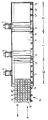
- the device consists of an evacuable prechamber 3, a process chamber 4 corresponding to it, the vacuum pumps 5, 6, 7 connected to the chambers 3, 4, the magnetron cathodes 8, 9 arranged in the process chamber 4, both of which are cathodes with two each Targets are formed (so-called twin mags), the substrate holder 10 and a device (not shown) for transporting the substrate holder 10 through the chambers 3, 4.
- the transport device can be formed from a chain of rollers 12, 12 ', ... , which are all driven by an electric motor and whose direction of rotation can be switched in each case.
- a lock 13 is provided between the two chambers 3, 4, which allows the substrate holder 10 to pass from the pre-chamber 3 into the process chamber 4 and vice versa.
- a further lock 14 is arranged in the wall of the pre-chamber 3, which allows the substrate holder 10 to enter the pre-chamber 3 from the supply station 15 or back into the preparation station 15.
- the substrate holder 10 with the attached to it Substrates 11, 11 ', 11'', ... moved in the arrow direction A through the lock 14 into the prechamber 3.
- the substrate holder 10 on the rollers 12, 12 ',... Continues in direction A to the first section I of the process chamber 4 transported, wherein both sections I and II are separated from each other by an aperture or a shield 16.
- the cathode 8 is arranged vertically, so that the individual substrates 11, 11 ', ... are coated evenly when moving in the direction of arrow A.
- the substrate holder 10 moves further into the part II of the process chamber 4, the substrates 11, 11 ', ... being provided with a further layer, since they all move past the cathode 9.
- the movement in the direction of arrow B is initiated by switching over the rotating device of the rollers 12, 12 ', ..., ie the substrate holder 10 is moved back into section I of the process chamber 4 and from here through the lock 13, which is open during the entire coating process, into the position shown in phantom in the pre-chamber 3, a third layer being applied from the cathode 8 to the substrates 11, 11 ',.
- the substrate carrier 10 can now oscillate back and forth between the dash-dotted and the dashed position or between the section III and the section I until the necessary layers are applied.
- the lock 13 is closed, the antechamber 3 is ventilated and the lock 14 is opened.
- optical multilayer systems on flat substrates are generally predestined for sputtering processes.
- the substrate carrier 10 reaches the prechamber 3 via a lock valve 14.
- the substrate carrier 10 is now moved alternately past the two coating stations. In this way, a package is formed from any number of individual layers, the thickness of which can be regulated via the sputtering power and the speed of the substrate carrier 10.
- a layer system with 15 individual layers is used as a design example.
- the coating performance is approx. 1 m 2 / h. This means that the cycle time for coating a carrier 10 is approximately 10 minutes.
- the sputtering system described is a conventional vapor deposition system (batch coater) think.
- the sputtering system described is a single-purpose system, which is preferably designed for coating flat substrates with optical multilayer systems.
Landscapes
- Chemical & Material Sciences (AREA)
- Engineering & Computer Science (AREA)
- Plasma & Fusion (AREA)
- Analytical Chemistry (AREA)
- Physics & Mathematics (AREA)
- Chemical Kinetics & Catalysis (AREA)
- Materials Engineering (AREA)
- Organic Chemistry (AREA)
- Mechanical Engineering (AREA)
- Metallurgy (AREA)
- Life Sciences & Earth Sciences (AREA)
- General Chemical & Material Sciences (AREA)
- Geochemistry & Mineralogy (AREA)
- Physical Vapour Deposition (AREA)
- Surface Treatment Of Optical Elements (AREA)
- Optical Filters (AREA)
Applications Claiming Priority (2)
| Application Number | Priority Date | Filing Date | Title |
|---|---|---|---|
| DE19500964A DE19500964A1 (de) | 1995-01-14 | 1995-01-14 | Vorrichtung zum Beschichten |
| DE19500964 | 1995-07-14 |
Publications (2)
| Publication Number | Publication Date |
|---|---|
| EP0753601A2 true EP0753601A2 (fr) | 1997-01-15 |
| EP0753601A3 EP0753601A3 (fr) | 1998-10-21 |
Family
ID=7751494
Family Applications (1)
| Application Number | Title | Priority Date | Filing Date |
|---|---|---|---|
| EP95111291A Withdrawn EP0753601A3 (fr) | 1995-01-14 | 1995-07-19 | Dispositif de revêtement |
Country Status (3)
| Country | Link |
|---|---|
| EP (1) | EP0753601A3 (fr) |
| JP (1) | JPH08232062A (fr) |
| DE (1) | DE19500964A1 (fr) |
Cited By (2)
| Publication number | Priority date | Publication date | Assignee | Title |
|---|---|---|---|---|
| WO2004042107A3 (fr) * | 2002-11-08 | 2005-09-01 | Applied Films Gmbh & Co Kg | Revetement destine a un substrat plastique |
| CN109023268A (zh) * | 2018-08-31 | 2018-12-18 | 重庆市渝大节能玻璃有限公司 | 玻璃镀膜加工用阴极底板清理机构 |
Families Citing this family (3)
| Publication number | Priority date | Publication date | Assignee | Title |
|---|---|---|---|---|
| JP4665155B2 (ja) * | 2004-10-22 | 2011-04-06 | 株式会社昭和真空 | 薄膜形成装置及びその方法 |
| DE102005016405A1 (de) * | 2005-04-08 | 2006-10-12 | Von Ardenne Anlagentechnik Gmbh | Vorrichtung zur Vakuumbeschichtung von Substraten unterschiedlicher Größe |
| DE102008024372B4 (de) * | 2008-05-20 | 2013-08-22 | Von Ardenne Anlagentechnik Gmbh | Verfahren zum Transport von Substraten in Vakuumbeschichtungseinrichtungen |
Citations (1)
| Publication number | Priority date | Publication date | Assignee | Title |
|---|---|---|---|---|
| DE4203473A1 (de) | 1992-02-07 | 1993-08-12 | Leybold Ag | Drehschleuse zum ein- und/oder ausbringen eines substrats aus der einen in eine benachbarte behandlungskammer |
Family Cites Families (9)
| Publication number | Priority date | Publication date | Assignee | Title |
|---|---|---|---|---|
| US4116806A (en) * | 1977-12-08 | 1978-09-26 | Battelle Development Corporation | Two-sided planar magnetron sputtering apparatus |
| DE3400843A1 (de) * | 1983-10-29 | 1985-07-18 | VEGLA Vereinigte Glaswerke GmbH, 5100 Aachen | Verfahren zum herstellen von autoglasscheiben mit streifenfoermigen blendschutzfiltern durch bedampfen oder sputtern, und vorrichtung zur durchfuehrung des verfahrens |
| AU572375B2 (en) * | 1985-01-31 | 1988-05-05 | Boc Group, Inc., The | Transporting of workpiece to and from vacuum coating apparatus |
| DE3612721C3 (de) * | 1986-04-16 | 1994-07-14 | Ver Glaswerke Gmbh | Durchlauf-Kathodenzerstäubungsanlage |
| US4920917A (en) * | 1987-03-18 | 1990-05-01 | Teijin Limited | Reactor for depositing a layer on a moving substrate |
| DE4005956C1 (fr) * | 1990-02-26 | 1991-06-06 | Siegfried Dipl.-Ing. Dr. 5135 Selfkant De Straemke | |
| US5232567A (en) * | 1990-09-29 | 1993-08-03 | Gold Star Co., Ltd. | Process for fabricating of a magneto-optical recording medium |
| DE4036339C2 (de) * | 1990-11-15 | 1993-10-21 | Leybold Ag | Vorrichtung für den Transport von Substraten |
| DE4111384C2 (de) * | 1991-04-09 | 1999-11-04 | Leybold Ag | Vorrichtung zur Beschichtung von Substraten |
-
1995
- 1995-01-14 DE DE19500964A patent/DE19500964A1/de not_active Withdrawn
- 1995-07-19 EP EP95111291A patent/EP0753601A3/fr not_active Withdrawn
-
1996
- 1996-01-12 JP JP8004106A patent/JPH08232062A/ja active Pending
Patent Citations (1)
| Publication number | Priority date | Publication date | Assignee | Title |
|---|---|---|---|---|
| DE4203473A1 (de) | 1992-02-07 | 1993-08-12 | Leybold Ag | Drehschleuse zum ein- und/oder ausbringen eines substrats aus der einen in eine benachbarte behandlungskammer |
Cited By (3)
| Publication number | Priority date | Publication date | Assignee | Title |
|---|---|---|---|---|
| WO2004042107A3 (fr) * | 2002-11-08 | 2005-09-01 | Applied Films Gmbh & Co Kg | Revetement destine a un substrat plastique |
| CN109023268A (zh) * | 2018-08-31 | 2018-12-18 | 重庆市渝大节能玻璃有限公司 | 玻璃镀膜加工用阴极底板清理机构 |
| CN109023268B (zh) * | 2018-08-31 | 2021-02-26 | 重庆市渝大节能玻璃有限公司 | 玻璃镀膜加工用阴极底板清理机构 |
Also Published As
| Publication number | Publication date |
|---|---|
| EP0753601A3 (fr) | 1998-10-21 |
| DE19500964A1 (de) | 1996-07-18 |
| JPH08232062A (ja) | 1996-09-10 |
Similar Documents
| Publication | Publication Date | Title |
|---|---|---|
| DE3786800T2 (de) | Anlage zur kontinuierlichen Verbundbeschichtung von bandförmigem Gut. | |
| DE69033441T2 (de) | Geometrie und Gestaltungen eines Geräts zum Magnetronzerstäuben | |
| DE68927920T2 (de) | Magnetronzerstäubungsanlage und -verfahren | |
| EP0943699B1 (fr) | Dispositif de sas pour le chargement et déchargement des substrats d'une chambre de traitement | |
| DE3925536A1 (de) | Anordnung zur dickenmessung von duennschichten | |
| DE4111384C2 (de) | Vorrichtung zur Beschichtung von Substraten | |
| DE4126236C2 (de) | Rotierende Magnetron-Kathode und Verwendung einer rotierenden Magnetron-Kathode | |
| EP1036212B1 (fr) | Dispositif de revetement sous vide de paliers lisses | |
| CH691376A5 (de) | Vakuumanlage zur Oberflächenbearbeitung von Werkstücken. | |
| DE69504716T2 (de) | System zum Behandeln und zum Handhaben von Substraten für Flachdisplays | |
| WO2006010451A2 (fr) | Installation de revetement sous vide et procede de revetement sous vide | |
| EP0783174B1 (fr) | Dispositif pour le revêtement d'un substrat | |
| DE2047749A1 (de) | Zirkuläres System zur kontinuierlichen Verrichtung verschiedener im Vakuum durch zuführender Prozesse | |
| EP2521804A1 (fr) | Installation de revêtement en ligne | |
| DE19606463C2 (de) | Mehrkammer-Kathodenzerstäubungsvorrichtung | |
| DE102004021734B4 (de) | Verfahren und Vorrichtung zur kontinuierlichen Beschichtung flacher Substrate mit optisch aktiven Schichtsystemen | |
| EP0753601A2 (fr) | Dispositif de revêtement | |
| EP0953657A2 (fr) | Appareillage de revêtement sous vide | |
| DE102012103254A1 (de) | Verfahren zum Einschleusen von Substraten in eine Vakuumbehandlungsanlage | |
| DE69215077T2 (de) | Verfahren und Vorrichtung zum Erzeugen von Dünnschichten | |
| DE102014107623B4 (de) | Prozessieranlage | |
| DE3242855A1 (de) | Verfahren und vorrichtung zur konturierung der dicke von aufgespruehten schichten | |
| DE69400404T2 (de) | Beschichtungsvorrichtung zum aufdampfen von metallischem material auf ein substrat | |
| DE10323295B4 (de) | Vakuumbeschichtungsanlage und Verfahren zur Beschichtung von Substraten | |
| EP4453270B1 (fr) | Système en ligne de revêtement de substrats individuels ou de groupes de substrats et procédé de revêtement de substrats individuels ou de groupes de substrats dans un système de revêtement en ligne |
Legal Events
| Date | Code | Title | Description |
|---|---|---|---|
| PUAI | Public reference made under article 153(3) epc to a published international application that has entered the european phase |
Free format text: ORIGINAL CODE: 0009012 |
|
| AK | Designated contracting states |
Kind code of ref document: A2 Designated state(s): CH DE ES FR GB IT LI |
|
| PUAL | Search report despatched |
Free format text: ORIGINAL CODE: 0009013 |
|
| AK | Designated contracting states |
Kind code of ref document: A3 Designated state(s): CH DE ES FR GB IT LI |
|
| 17P | Request for examination filed |
Effective date: 19981106 |
|
| 17Q | First examination report despatched |
Effective date: 20001211 |
|
| STAA | Information on the status of an ep patent application or granted ep patent |
Free format text: STATUS: THE APPLICATION IS DEEMED TO BE WITHDRAWN |
|
| 18D | Application deemed to be withdrawn |
Effective date: 20010424 |