EP0753694A1 - Vanne pyrotechnique à commande électrique - Google Patents
Vanne pyrotechnique à commande électrique Download PDFInfo
- Publication number
- EP0753694A1 EP0753694A1 EP96810428A EP96810428A EP0753694A1 EP 0753694 A1 EP0753694 A1 EP 0753694A1 EP 96810428 A EP96810428 A EP 96810428A EP 96810428 A EP96810428 A EP 96810428A EP 0753694 A1 EP0753694 A1 EP 0753694A1
- Authority
- EP
- European Patent Office
- Prior art keywords
- valve
- cartridge
- piston
- rod
- screwed
- Prior art date
- Legal status (The legal status is an assumption and is not a legal conclusion. Google has not performed a legal analysis and makes no representation as to the accuracy of the status listed.)
- Granted
Links
- 239000002360 explosive Substances 0.000 claims abstract description 22
- 238000004880 explosion Methods 0.000 claims description 9
- 230000000903 blocking effect Effects 0.000 claims 6
- 238000007789 sealing Methods 0.000 abstract description 3
- 230000000977 initiatory effect Effects 0.000 abstract 1
- 239000012530 fluid Substances 0.000 description 7
- 229910000831 Steel Inorganic materials 0.000 description 3
- 239000010959 steel Substances 0.000 description 3
- 239000004020 conductor Substances 0.000 description 2
- 239000007789 gas Substances 0.000 description 2
- 238000009434 installation Methods 0.000 description 2
- 239000002184 metal Substances 0.000 description 2
- 230000006835 compression Effects 0.000 description 1
- 238000007906 compression Methods 0.000 description 1
- 230000000694 effects Effects 0.000 description 1
- 238000010304 firing Methods 0.000 description 1
- 238000010438 heat treatment Methods 0.000 description 1
- 230000000149 penetrating effect Effects 0.000 description 1
- XLYOFNOQVPJJNP-UHFFFAOYSA-N water Substances O XLYOFNOQVPJJNP-UHFFFAOYSA-N 0.000 description 1
Images



Classifications
-
- F—MECHANICAL ENGINEERING; LIGHTING; HEATING; WEAPONS; BLASTING
- F42—AMMUNITION; BLASTING
- F42B—EXPLOSIVE CHARGES, e.g. FOR BLASTING, FIREWORKS, AMMUNITION
- F42B3/00—Blasting cartridges, i.e. case and explosive
- F42B3/006—Explosive bolts; Explosive actuators
-
- F—MECHANICAL ENGINEERING; LIGHTING; HEATING; WEAPONS; BLASTING
- F16—ENGINEERING ELEMENTS AND UNITS; GENERAL MEASURES FOR PRODUCING AND MAINTAINING EFFECTIVE FUNCTIONING OF MACHINES OR INSTALLATIONS; THERMAL INSULATION IN GENERAL
- F16K—VALVES; TAPS; COCKS; ACTUATING-FLOATS; DEVICES FOR VENTING OR AERATING
- F16K13/00—Other constructional types of cut-off apparatus; Arrangements for cutting-off
- F16K13/04—Other constructional types of cut-off apparatus; Arrangements for cutting-off with a breakable closure member
- F16K13/06—Other constructional types of cut-off apparatus; Arrangements for cutting-off with a breakable closure member constructed to be ruptured by an explosion
Definitions
- the present invention relates to a valve equipped with electrically actuated actuating means.
- valves In known electrically operated valves, the valve is actuated by means of an electromagnet, generally an electromagnet with a plunger core fixed directly to the valve and acting against the force of a spring which holds the valve in a first position, for example, against its seat, when the electromagnet coil is not energized.
- an electromagnet generally an electromagnet with a plunger core fixed directly to the valve and acting against the force of a spring which holds the valve in a first position, for example, against its seat, when the electromagnet coil is not energized.
- the sprinklers of the installation instantly sprinkle the fire, with a relatively high flow rate, when the fire detectors send a control signal to the valves.
- the water pressure must also be high.
- the object of the invention is to produce an instantaneous valve, of small volume, consuming very little electrical current and inexpensive.
- the valve according to the invention is characterized in that its actuation means consist of an electrically ignited explosive cartridge.
- the response time of such a valve is of the order of a millisecond, a response time that it is practically impossible to obtain by means of an electromagnet.
- the explosive cartridge is a low-cost, low-volume item. It can be easily replaced with a new cartridge.
- the actuating force is such that the valve can be held in the initial position very securely by an oversized element, in particular a spring.
- the valve can therefore be used for all fluid pressures and for all fluids. The actuation of the valve is also guaranteed.
- the electric firing of an explosive cartridge requires only a small electric current, so that the supply network does not need to be able to withstand high currents and that it is even possible to control such a valve or a battery of such valves by means of an autonomous current source, for example a battery or an accumulator.
- the cartridge is cylindrical and provided with a piston closing the cartridge in a sealed manner so that the pressure of the gases released by the explosion is maintained in the cartridge, which makes it possible to produce a very simple valve, the valve of which is kept actuated, against the pressure of a strong spring, by the piston of the explosive cartridge.
- Explosive cartridge actuation is applicable to a two- or three-way valve or more.
- the valve can be fitted with several explosive cartridges.
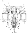
- Figure 1 is an axial sectional view of a two-way valve according to a first embodiment, in the closed position.
- Figure 2 shows the same valve in the open position, after explosion of the cartridge.
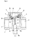
- Figure 3 is an axial sectional view of a two-way valve according to a second embodiment, showing the valve in the closed position and in the open position.
- Figure 4 is an axial section of a two-way valve according to a third embodiment showing the valve in the closed position and in the open position.
- Figure 5 is an axial sectional view of a two-way valve according to a fourth embodiment, showing the valve in the closed position and in the open position.
- the valve shown in Figure 1 includes a valve body 1 having an inlet 2 and an outlet 3 aligned between them and a valve seat 4, a cover 5 fixed to the body 1 by means of four screws 6 with the interposition of a seal 7, a valve 8 formed halfway up a valve stem 9 for the valve guide, a spring 10 working in compression between the cover 5 and the valve 8 to keep this valve applied on its seat 4, a steel sleeve 11 screwed into an orifice of the valve body 1 coaxially with the axis of the valve 8 and an explosive cartridge 12 consisting of a socket closed by a hexagonal head 12a and having a threaded portion 12b making it possible to screw the explosive cartridge 12 into the socket 11.
- the socket 11 has at its inner end a narrowing 11a used for guiding the rod 9 of the valve. Seals 13 and 14 respectively ensure the seal between the socket 11 and the valve body and between the explosive cartridge 12 and the socket 11. From the explosive cartridge 12, two insulated conductors 15 and 16 leave.
- the cartridge 12 contains a steel piston 17 with which is associated a plastic cylinder 18.
- the piston rod 17 is guided by a narrowing of the cartridge.
- the explosive 19 is ignited by the heating of a filament 20 connected to the conductors 15 and 16.
- valve Before the explosion of the cartridge, the valve is closed as shown in Figure 1.
- the valve 8 is applied strongly against its seat 4 by its spring 10 which can be without other very widely dimensioned.
- the piston 17 Under the effect of the explosion, the piston 17 is instantly pushed forward and opens the valve 8 by pushing it back by the end of its rod 9.
- the piston 18 made of plastic, very strongly pressed against the wall of the cartridge, ensures a hermetic closure of the cartridge. The pressure of the explosion gases in the cartridge is thus maintained and the piston 17 remains in the position shown in FIG. 2, in abutment against the cover 5, keeping the valve open.
- valve is of very simple design. To reset the valve, simply unscrew the cartridge 12 and replace it with a new cartridge.
- inventions shown in Figures 3 to 5 differ essentially from the first embodiment in that the explosive cartridge 12 is not hermetically closed after explosion. This is the case if the cartridge has only a metal piston.
- the valve shown in Figure 3 is provided with a cylindrical valve 22 mounted in a bore 23 formed in the cover 5 screwed into the body 1.
- the valve 22 is further provided with an attached rod 24 and a gasket 25 sealing the closure of the seat 4.
- the interior of the bore 23 forms with the valve 22 a chamber communicating with the inlet 2 by a groove 26 formed in the wall of the bore. In the bore 23 thus prevails a pressure equal to the pressure of the fluid in the inlet 2. This pressure is therefore added to the force of the spring 10 to keep the valve closed, so that the spring 10 can be relatively weak.
- valve In the left half of the figure, the valve is shown in the closed position, the piston 17 of the explosive cartridge 12 being retracted inside the cartridge and the rod 24 of the valve being almost in contact with the cartridge 12. After explosion of the cartridge, the valve occupies the position shown in the right part of the drawing. The piston 17 has pushed back the valve 22 which is kept open, in a known manner, by the pressure of the fluid flowing through the valve.
- Figure 3 shows the piston 22 in the intermediate position. At the end of the race, it abuts at the bottom of the bore 23 and remains in this position.
- the valve according to the third embodiment, shown in Figure 4 also includes a cover 5 screwed into the valve body 1 and a cylindrical valve 32 mounted in a bore 33 of the cover 5.
- the valve 32 has a central orifice defining an auxiliary seat 34 closed by an auxiliary valve 35 provided with a lining 36 and a cylindrical valve stem 37 mounted in a bore 38 formed in the cover 5.
- the stem 37 carries an O-ring 39 ensuring sealing.
- the auxiliary valve 35 is further provided with a rod 40 extending as close to the explosive cartridge 12. It will have been recognized that this valve is a servo-controlled valve.
- the left half of Figure 4 shows the valve in the closed position.
- the valve body 1 does not have a lateral hole for fixing an explosive cartridge, the explosive cartridge 12 being screwed into a metal body 41 which replaces the cover 5 and which is, like him, screwed into the valve body 1 with the interposition of a seal 7.
- the valve comprises a cylindrical valve 42 sliding in a bore 43 formed in the body 41.
- the valve 42 is provided with a rod 44 penetrating into the body 41.
- This body 41 has a hole 45 located in the extension of the cartridge 12 and in which a steel ball 46 is disposed.
- the hole 45 is closed by a screw 47 provided with a cylindrical extension 48 wearing an O-ring 49.
- the ball 46 is returned to the initial locking position by means of the screw 47. It can therefore be seen that the only function of the spring 10 is to facilitate the return of the ball 46 to the locking position.
- the spring 10 can therefore be very weak.
- the ball 46 could be replaced by any other locking part capable of being displaced by the explosion of the cartridge.
- Explosive cartridge actuation is applicable to any type of valve, any fluid and any pressure.
Landscapes
- Engineering & Computer Science (AREA)
- General Engineering & Computer Science (AREA)
- Mechanical Engineering (AREA)
- Safety Valves (AREA)
Abstract
Description
- La présente invention a pour objet une vanne équipée de moyens d'actionnement à commande électrique.
- Dans les vannes à commande électrique connues, le clapet est actionné au moyen d'un électroaimant, généralement un électroaimant à noyau plongeur fixé directement au clapet et agissant contre la force d'un ressort qui maintient le clapet dans une première position, par exemple, contre son siège, lorsque la bobine de l'électroaimant n'est pas alimentée.
- Dans certaines applications, telles que les installations automatiques d'extinction de feu dans des immeubles, il est souhaité que les gicleurs de l'installation aspergent instantanément le feu, avec un débit relativement important, lorsque les détecteurs de feu envoient un signal de commande aux vannes. La pression de l'eau doit en outre être élevée.
- Or, pour assurer l'ouverture instantanée d'une vanne capable d'assurer un débit suffisant, il serait nécessaire d'utiliser un électroaimant très puissant, c'est-à-dire très gros et surdimensionné. De telles vannes seraient très lourdes, encombrantes et coûteuses. Des essais ont montré que le temps de réponse d'une telle vanne est malgré tout encore de l'ordre d'une dizaine de millisecondes. La commande de telles électrovannes exige en outre un courant de haute intensité. Dans le cas où un grand nombre de vannes devraient être commandées simultanément, le courant sur le réseau d'alimentation atteindrait des valeurs inadmissibles.
- L'invention a pour but de réaliser une vanne à fonctionnement instantané, de faible volume, consommant très peu de courant électrique et peu coûteuse.
- La vanne selon l'invention est caractérisée en ce que ses moyens d'actionnement sont constitués d'une cartouche explosive mise à feu électriquement.
- Le temps de réponse d'une telle valve est de l'ordre d'une milliseconde, temps de réponse qu'il est pratiquement impossible d'obtenir au moyen d'un électroaimant. La cartouche explosive est un élément bon marché et de faible volume. Elle peut être facilement remplacée par une nouvelle cartouche.
- En outre, la force d'actionnement est telle que le clapet peut être maintenu en position initiale de façon très sûre par un élément surdimensionné, en particulier un ressort. La vanne est donc utilisable pour toutes pressions de fluide et pour tous fluides. L'actionnement de la vanne est en outre garanti.
- La mise à feu électrique d'une cartouche explosive ne nécessite qu'un faible courant électrique, de telle sorte que le réseau d'alimentation n'a pas besoin d'être en mesure de supporter des courants élevés et qu'il est même possible de commander une telle valve ou une batterie de telles valves au moyen d'une source de courant autonome, par exemple une pile ou un accumulateur.
- Selon une forme d'exécution préférée de l'invention, la cartouche est cylindrique et munie d'un piston fermant la cartouche de manière étanche de telle sorte que la pression des gaz dégagés par l'explosion est maintenue dans la cartouche, ce qui permet de réaliser une vanne très simple dont le clapet est maintenu actionné, contre la pression d'un fort ressort, par le piston de la cartouche explosive.
- L'actionnement par cartouche explosive est applicable à une vanne à deux ou trois voies ou davantage. La vanne peut être équipée de plusieurs cartouches explosives.
- Le dessin annexé représente, à titre d'exemple, quatre formes d'exécution de la vanne selon l'invention.
- La figure 1 est une vue en coupe axiale d'une vanne à deux voies selon une première forme d'exécution, en position fermée.
- La figure 2 représente la même vanne en position ouverte, après explosion de la cartouche.
- La figure 3 est une vue en coupe axiale d'une vanne à deux voies selon une deuxième forme d'exécution, représentant la vanne en position fermée et en position ouverte.
- La figure 4 est une coupe axiale d'une vanne à deux voies selon une troisième forme d'exécution montrant la vanne en position fermée et en position ouverte.
- La figure 5 est une vue en coupe axiale d'une vanne à deux voies selon une quatrième forme d'exécution, montrant la vanne en position fermée et en position ouverte.
- La vanne représentée à la figure 1 comprend un corps de vanne 1 présentant une entrée 2 et une sortie 3 alignées entre elles et un siège de clapet 4, un couvercle 5 fixé sur le corps 1 au moyen de quatre vis 6 avec interposition d'une garniture d'étanchéité 7, un clapet 8 formé à mi-hauteur d'une tige de clapet 9 pour le guidage du clapet, un ressort 10 travaillant en compression entre le couvercle 5 et le clapet 8 pour maintenir ce clapet appliqué sur son siège 4, une douille en acier 11 vissée dans un orifice du corps de vanne 1 coaxialement à l'axe du clapet 8 et une cartouche explosive 12 constituée d'une douille fermée par une tête hexagonale 12a et présentant une partie filetée 12b permettant de visser la cartouche explosive 12 dans la douille 11. La douille 11 présente à son extrémité intérieure un rétrécissement 11a servant au guidage de la tige 9 du clapet. Des garnitures d'étanchéité 13 et 14 assurent respectivement l'étanchéité entre la douille 11 et le corps de vanne et entre la cartouche explosive 12 et la douille 11. De la cartouche explosive 12 partent deux conducteurs isolés 15 et 16.
- La cartouche 12 contient un piston 17 en acier auquel est associé un cylindre de matière plastique 18. La tige du piston 17 est guidée par un rétrécissement de la cartouche. L'explosif 19 est mis à feu par l'échauffement d'un filament 20 relié aux conducteurs 15 et 16.
- Avant l'explosion de la cartouche, la vanne est fermée comme représentée à la figure 1. Le clapet 8 est appliqué fortement contre son siège 4 par son ressort 10 qui peut être sans autre très largement dimensionné.
- Sous l'effet de l'explosion, le piston 17 est poussé instantanément en avant et vient ouvrir le clapet 8 en le repoussant par l'extrémité de sa tige 9. Le piston 18 en matière plastique, très fortement pressé contre la paroi de la cartouche, assure une fermeture hermétique de la cartouche. La pression des gaz d'explosion dans la cartouche est ainsi maintenue et le piston 17 reste dans la position représentée à la figure 2, en butée contre le couvercle 5, en maintenant la vanne ouverte.
- On constate que la vanne est de conception très simple. Pour réarmer la vanne, il suffit de dévisser la cartouche 12 et de la remplacer par une nouvelle cartouche.
- On décrira maintenant d'autres formes d'exécution en relation avec les figures 3, 4 et 5. De manière à simplifier la description et éviter des répétitions, les éléments essentiels que l'on retrouve dans toutes les formes d'exécution seront désignés par les mêmes références que dans les figures 1 et 2, même si elles présentent une forme différente.
- Les formes d'exécution représentées aux figures 3 à 5 différent essentiellement de la première forme d'exécution en ce que la cartouche explosive 12 n'est pas fermée hermétiquement après explosion. Ceci est le cas si la cartouche est munie uniquement d'un piston en métal.
- La vanne représentée à la figure 3 est munie d'un clapet cylindrique 22 monté dans un alésage 23 formé dans le couvercle 5 vissé dans le corps 1. Le clapet 22 est en outre muni d'une tige rapportée 24 et d'une garniture 25 assurant l'étanchéité de la fermeture du siège 4. L'intérieur de l'alésage 23 forme avec le clapet 22 une chambre communiquant avec l'entrée 2 par une rainure 26 formée dans la paroi de l'alésage. Dans l'alésage 23 règne ainsi une pression égale à la pression du fluide dans l'entrée 2. Cette pression s'ajoute donc à la force du ressort 10 pour maintenir la vanne fermée, de sorte que le ressort 10 peut être relativement faible.
- Dans la moitié gauche de la figure, la vanne est représentée en position fermée, le piston 17 de la cartouche explosive 12 étant rétracté à l'intérieur de la cartouche et la tige 24 du clapet étant presque en contact avec la cartouche 12. Après explosion de la cartouche, la vanne occupe la position représentée dans la partie droite du dessin. Le piston 17 a repoussé le clapet 22 qui est maintenu ouvert, de manière connue, par la pression du fluide s'écoulant à travers la vanne. La figure 3 représente le piston 22 en position intermédiaire. En fin de course, il vient buter au fond de l'alésage 23 et reste dans cette position.
- La vanne selon la troisième forme d'exécution, représentée à la figure 4, comprend également un couvercle 5 vissé dans le corps de valve 1 et un clapet 32 cylindrique monté dans un alésage 33 du couvercle 5. Le clapet 32 présente un orifice central définissant un siège auxiliaire 34 fermé par un clapet auxiliaire 35 muni d'une garniture 36 et d'une tige de clapet cylindrique 37 montée dans un alésage 38 formé dans le couvercle 5. La tige 37 porte un O-ring 39 assurant l'étanchéité. Le clapet auxiliaire 35 est en outre muni d'une tige 40 s'étendant jusqu'à proximité de la cartouche explosive 12. On aura reconnu que cette vanne est une vanne servo-commandée. La moitié gauche de la figure 4 représente la vanne en position fermée.
- Lors de l'explosion de la cartouche 12, son piston 17 repousse la tige 40 et ouvre le clapet auxiliaire 35. La pression dans la chambre 33 chute brusquement de telle sorte que le clapet principal 32 peut être repoussé par la pression d'entrée et qu'il est maintenu repoussé par la pression du fluide traversant la vanne.
- Dans la quatrième forme d'exécution, représentée à la figure 5, le corps de vanne 1 ne présente pas de trou latéral pour la fixation d'une cartouche explosive, la cartouche explosive 12 étant vissée dans un corps métallique 41 qui remplace le couvercle 5 et qui est, comme lui, vissé dans le corps de vanne 1 avec interposition d'une garniture d'étanchéité 7. La vanne comprend un clapet cylindrique 42 coulissant dans un alésage 43 formé dans le corps 41. Le clapet 42 est muni d'une tige 44 pénétrant dans le corps 41. Ce corps 41 présente un trou 45 situé dans le prolongement de la cartouche 12 et dans lequel est disposée une bille en acier 46. Le trou 45 est fermé par une vis 47 munie d'un prolongement cylindrique 48 portant un O-ring 49.
- Dans la position fermée de la vanne représentée dans la demi-coupe de la moitié gauche du dessin, la bille 46 est située en face de l'extrémité de la tige 44 du clapet qui s'appuie contre la bille en pressant la garniture 25 sur le siège 4.
- Lors de l'explosion de la cartouche 12, la bille 46 est repoussée contre la vis 47 par le piston 17 de la cartouche. Le clapet 42 est alors libéré et il est repoussé par la pression du fluide dans la position représentée dans la demi-coupe de la moitié droite du dessin.
- En vue de la réutilisation de la vanne, la bille 46 est ramenée en position initiale de verrouillage au moyen de la vis 47. On voit donc que la seule fonction du ressort 10 est de faciliter le retour de la bille 46 en position de verrouillage. Le ressort 10 peut donc être très faible.
- La bille 46 pourrait être remplacée par toute autre pièce de verrouillage susceptible d'être déplacée par l'explosion de la cartouche.
- La vanne pourrait bien entendu être commandée à la fermeture. L'actionnement par cartouche explosive est applicable à tout type de vanne, à tout fluide et pour toute pression.
Claims (7)
- Vanne équipée de moyens d'actionnement à commande électrique, caractérisée en ce que les moyens d'actionnement sont constitués d'une cartouche explosive (12) mise à feu électriquement.
- Vanne selon la revendication 1, comprenant un clapet (8; 22) maintenu dans une position initiale par un moyen élastique (10), caractérisée en ce que la cartouche explosive (12) est munie d'un piston (17) actionnant directement le clapet.
- Vanne selon la revendication 2, caractérisée en ce que le piston (17, 18) assure une fermeture étanche de la cartouche (12), de telle sorte que le piston est maintenu en position d'actionnement après explosion.
- Vanne selon la revendication 1, comprenant une chambre de servo-commande (33) en arrière d'un clapet principal (32) maintenu contre un siège (4) par un moyen élastique (10) et un clapet auxiliaire (35) destiné à mettre en communication la chambre de servo-commande avec la sortie de la vanne, caractérisée en ce que la cartouche explosive (12) est munie d'un piston (17) actionnant le clapet auxiliaire.
- Vanne selon la revendication 1, caractérisée en ce qu'elle comprend une pièce de blocage (46) du clapet (42) en position initiale, cette pièce de blocage étant susceptible de se déplacer par poussée dans un guidage transversalement à la direction de déplacement du clapet et en ce que la cartouche explosive (12) est disposée de manière à déplacer cette pièce de blocage et à libérer ainsi le clapet.
- Vanne selon la revendication 5, caractérisée en ce qu'elle est munie d'une vis de réarmage (47) permettant de repousser ladite pièce de blocage (46) dans sa position de blocage.
- Vanne selon la revendication 6, caractérisée en ce que la pièce de blocage (46) est une bille.
Applications Claiming Priority (3)
| Application Number | Priority Date | Filing Date | Title |
|---|---|---|---|
| CH2079/95 | 1995-07-14 | ||
| CH02079/95A CH689839A5 (fr) | 1995-07-14 | 1995-07-14 | Vanne à commande électrique. |
| CH207995 | 1995-07-14 |
Publications (2)
| Publication Number | Publication Date |
|---|---|
| EP0753694A1 true EP0753694A1 (fr) | 1997-01-15 |
| EP0753694B1 EP0753694B1 (fr) | 2000-01-12 |
Family
ID=4225417
Family Applications (1)
| Application Number | Title | Priority Date | Filing Date |
|---|---|---|---|
| EP19960810428 Expired - Lifetime EP0753694B1 (fr) | 1995-07-14 | 1996-06-27 | Vanne pyrotechnique à commande électrique |
Country Status (3)
| Country | Link |
|---|---|
| EP (1) | EP0753694B1 (fr) |
| CH (1) | CH689839A5 (fr) |
| DE (1) | DE69606111D1 (fr) |
Cited By (5)
| Publication number | Priority date | Publication date | Assignee | Title |
|---|---|---|---|---|
| DE10357423A1 (de) * | 2003-12-04 | 2005-06-30 | Rolls-Royce Deutschland Ltd & Co Kg | Schnellschlussventil zum Unterbrechen eines Fluidstroms |
| DE102010009878A1 (de) * | 2010-03-02 | 2011-09-08 | Rolls-Royce Deutschland Ltd & Co Kg | Fluidstromunterbrechungsvorrichtung |
| CN103307343A (zh) * | 2013-05-14 | 2013-09-18 | 哈尔滨工程大学 | 爆燃冲击开启的短冲程快速释放阀 |
| CN112984186A (zh) * | 2021-02-05 | 2021-06-18 | 优普能源技术有限公司 | 一种拉断阀 |
| CN113847466A (zh) * | 2021-10-20 | 2021-12-28 | 武汉船用电力推进装置研究所(中国船舶重工集团公司第七一二研究所) | 一种可拆卸式小型化电爆阀 |
Citations (5)
| Publication number | Priority date | Publication date | Assignee | Title |
|---|---|---|---|---|
| US2020833A (en) * | 1930-05-12 | 1935-11-12 | Refrigerating Specialties Comp | Electrically controlled valve |
| US3017894A (en) * | 1960-04-04 | 1962-01-23 | Futurecraft Corp | Valve |
| US3141470A (en) * | 1961-04-21 | 1964-07-21 | Koehler Aircraft Products Comp | Valve assembly |
| US3473543A (en) * | 1964-07-13 | 1969-10-21 | Conax Corp | Chip-free explosively actuated valve |
| FR2644869A1 (fr) * | 1989-03-21 | 1990-09-28 | Socira | Dispositif d'ouverture pour reservoir sous pression |
-
1995
- 1995-07-14 CH CH02079/95A patent/CH689839A5/fr not_active IP Right Cessation
-
1996
- 1996-06-27 DE DE69606111T patent/DE69606111D1/de not_active Expired - Lifetime
- 1996-06-27 EP EP19960810428 patent/EP0753694B1/fr not_active Expired - Lifetime
Patent Citations (5)
| Publication number | Priority date | Publication date | Assignee | Title |
|---|---|---|---|---|
| US2020833A (en) * | 1930-05-12 | 1935-11-12 | Refrigerating Specialties Comp | Electrically controlled valve |
| US3017894A (en) * | 1960-04-04 | 1962-01-23 | Futurecraft Corp | Valve |
| US3141470A (en) * | 1961-04-21 | 1964-07-21 | Koehler Aircraft Products Comp | Valve assembly |
| US3473543A (en) * | 1964-07-13 | 1969-10-21 | Conax Corp | Chip-free explosively actuated valve |
| FR2644869A1 (fr) * | 1989-03-21 | 1990-09-28 | Socira | Dispositif d'ouverture pour reservoir sous pression |
Cited By (7)
| Publication number | Priority date | Publication date | Assignee | Title |
|---|---|---|---|---|
| DE10357423A1 (de) * | 2003-12-04 | 2005-06-30 | Rolls-Royce Deutschland Ltd & Co Kg | Schnellschlussventil zum Unterbrechen eines Fluidstroms |
| US7163186B2 (en) | 2003-12-04 | 2007-01-16 | Rolls-Royce Deutschland Ltd & Co Kg | Quick-closing valve for the interruption of a fluid flow |
| DE102010009878A1 (de) * | 2010-03-02 | 2011-09-08 | Rolls-Royce Deutschland Ltd & Co Kg | Fluidstromunterbrechungsvorrichtung |
| CN103307343A (zh) * | 2013-05-14 | 2013-09-18 | 哈尔滨工程大学 | 爆燃冲击开启的短冲程快速释放阀 |
| CN112984186A (zh) * | 2021-02-05 | 2021-06-18 | 优普能源技术有限公司 | 一种拉断阀 |
| CN112984186B (zh) * | 2021-02-05 | 2022-12-02 | 优捷特清洁能源有限公司 | 一种拉断阀 |
| CN113847466A (zh) * | 2021-10-20 | 2021-12-28 | 武汉船用电力推进装置研究所(中国船舶重工集团公司第七一二研究所) | 一种可拆卸式小型化电爆阀 |
Also Published As
| Publication number | Publication date |
|---|---|
| EP0753694B1 (fr) | 2000-01-12 |
| DE69606111D1 (de) | 2000-02-17 |
| CH689839A5 (fr) | 1999-12-15 |
Similar Documents
| Publication | Publication Date | Title |
|---|---|---|
| FR2673261A1 (fr) | Dispositif formant soupape. | |
| EP0225225B1 (fr) | Valve d'alimentation d'une capacité puis de décharge brutale de cette capacité | |
| FR2892799A1 (fr) | Dispositif de commande du remplissage et/ou du soutirage de fluide et reservoir comportant un tel dispositif | |
| FR2704924A1 (fr) | Vanne pyrotechnique. | |
| EP1160461B1 (fr) | Actionneur pyrotechnique à membrane déformable | |
| CH689839A5 (fr) | Vanne à commande électrique. | |
| FR2502729A1 (fr) | Vanne en tout ou rien a declenchement pyrotechnique | |
| FR2535435A1 (fr) | Valve d'arret a commande hydraulique en particulier pour la securite en cas de rupture de tuyauterie | |
| FR2701531A1 (fr) | Electrovalve pneumatique proportionnelle. | |
| EP3098403B1 (fr) | Dispositif de commande d'une alimentation en fluide sous pression | |
| EP0128096A1 (fr) | Actionneur à accumulateur d'énergie pneumatique notamment pour robinet | |
| FR2562631A1 (fr) | Soupape de commande pour fluide et appareil de pompage pour injection de carburant la comportant | |
| FR2583506A1 (fr) | Robinet a gaz muni d'une soupape de securite et presentant un encombrement en hauteur reduit, pour plaques chauffantes et appareils de cuisson a gaz, en particulier pour cuisinieres | |
| CA2719464A1 (fr) | Dispositif receveur de gaz sous pression, ensemble distributeur-dispositif receveur, et systeme d'alimentation correspondant | |
| EP0591064B1 (fr) | Actionneur électro-hydraulique | |
| CA2601763C (fr) | Dispositif de protection contre une surpression et sous-ensemble de raccordement en comportant application | |
| FR2537689A1 (fr) | Vanne d'extincteur a pression de fluide permanente | |
| FR2563312A1 (fr) | Soupape de reduction de pression | |
| FR2565667A1 (fr) | Robinet a gaz perfectionne pour l'alimentation d'un bruleur. | |
| FR2635178A1 (fr) | Dispositif d'ouverture d'empennage pour obus | |
| FR2587418A1 (fr) | Dispositif de commutation electrohydraulique | |
| WO1991003638A1 (fr) | Allumeur de securite pour propulseur | |
| FR2781861A1 (fr) | Dispositif de commande d'une vanne quart de tour | |
| FR2589976A2 (en) | Extinguisher valve with permanent fluid pressure | |
| EP0681129B1 (fr) | Valve hydraulique à commande électromagnétique pulsée |
Legal Events
| Date | Code | Title | Description |
|---|---|---|---|
| PUAI | Public reference made under article 153(3) epc to a published international application that has entered the european phase |
Free format text: ORIGINAL CODE: 0009012 |
|
| AK | Designated contracting states |
Kind code of ref document: A1 Designated state(s): DE DK FR GB IT NL SE |
|
| 17P | Request for examination filed |
Effective date: 19970128 |
|
| RAP1 | Party data changed (applicant data changed or rights of an application transferred) |
Owner name: PARKER LUCIFER SA |
|
| 17Q | First examination report despatched |
Effective date: 19980923 |
|
| GRAG | Despatch of communication of intention to grant |
Free format text: ORIGINAL CODE: EPIDOS AGRA |
|
| GRAG | Despatch of communication of intention to grant |
Free format text: ORIGINAL CODE: EPIDOS AGRA |
|
| GRAH | Despatch of communication of intention to grant a patent |
Free format text: ORIGINAL CODE: EPIDOS IGRA |
|
| GRAH | Despatch of communication of intention to grant a patent |
Free format text: ORIGINAL CODE: EPIDOS IGRA |
|
| GRAA | (expected) grant |
Free format text: ORIGINAL CODE: 0009210 |
|
| AK | Designated contracting states |
Kind code of ref document: B1 Designated state(s): DE DK FR GB IT NL SE |
|
| PG25 | Lapsed in a contracting state [announced via postgrant information from national office to epo] |
Ref country code: SE Free format text: THE PATENT HAS BEEN ANNULLED BY A DECISION OF A NATIONAL AUTHORITY Effective date: 20000112 Ref country code: NL Free format text: LAPSE BECAUSE OF FAILURE TO SUBMIT A TRANSLATION OF THE DESCRIPTION OR TO PAY THE FEE WITHIN THE PRESCRIBED TIME-LIMIT Effective date: 20000112 Ref country code: IT Free format text: LAPSE BECAUSE OF FAILURE TO SUBMIT A TRANSLATION OF THE DESCRIPTION OR TO PAY THE FEE WITHIN THE PRE;WARNING: LAPSES OF ITALIAN PATENTS WITH EFFECTIVE DATE BEFORE 2007 MAY HAVE OCCURRED AT ANY TIME BEFORE 2007. THE CORRECT EFFECTIVE DATE MAY BE DIFFERENT FROM THE ONE RECORDED.SCRIBED TIME-LIMIT Effective date: 20000112 Ref country code: GB Free format text: LAPSE BECAUSE OF FAILURE TO SUBMIT A TRANSLATION OF THE DESCRIPTION OR TO PAY THE FEE WITHIN THE PRESCRIBED TIME-LIMIT Effective date: 20000112 |
|
| REF | Corresponds to: |
Ref document number: 69606111 Country of ref document: DE Date of ref document: 20000217 |
|
| PG25 | Lapsed in a contracting state [announced via postgrant information from national office to epo] |
Ref country code: DK Free format text: LAPSE BECAUSE OF FAILURE TO SUBMIT A TRANSLATION OF THE DESCRIPTION OR TO PAY THE FEE WITHIN THE PRESCRIBED TIME-LIMIT Effective date: 20000412 |
|
| PG25 | Lapsed in a contracting state [announced via postgrant information from national office to epo] |
Ref country code: DE Free format text: LAPSE BECAUSE OF FAILURE TO SUBMIT A TRANSLATION OF THE DESCRIPTION OR TO PAY THE FEE WITHIN THE PRESCRIBED TIME-LIMIT Effective date: 20000413 |
|
| NLV1 | Nl: lapsed or annulled due to failure to fulfill the requirements of art. 29p and 29m of the patents act | ||
| GBV | Gb: ep patent (uk) treated as always having been void in accordance with gb section 77(7)/1977 [no translation filed] |
Effective date: 20000112 |
|
| PLBE | No opposition filed within time limit |
Free format text: ORIGINAL CODE: 0009261 |
|
| STAA | Information on the status of an ep patent application or granted ep patent |
Free format text: STATUS: NO OPPOSITION FILED WITHIN TIME LIMIT |
|
| 26N | No opposition filed | ||
| PG25 | Lapsed in a contracting state [announced via postgrant information from national office to epo] |
Ref country code: FR Free format text: LAPSE BECAUSE OF NON-PAYMENT OF DUE FEES Effective date: 20010831 |
|
| REG | Reference to a national code |
Ref country code: FR Ref legal event code: ST |
|
| PG25 | Lapsed in a contracting state [announced via postgrant information from national office to epo] |
Ref country code: FR Free format text: LAPSE BECAUSE OF NON-PAYMENT OF DUE FEES Effective date: 20000630 |