EP0753746A2 - Récipient pour réactif intégrable dans un analyseur - Google Patents
Récipient pour réactif intégrable dans un analyseur Download PDFInfo
- Publication number
- EP0753746A2 EP0753746A2 EP96890113A EP96890113A EP0753746A2 EP 0753746 A2 EP0753746 A2 EP 0753746A2 EP 96890113 A EP96890113 A EP 96890113A EP 96890113 A EP96890113 A EP 96890113A EP 0753746 A2 EP0753746 A2 EP 0753746A2
- Authority
- EP
- European Patent Office
- Prior art keywords
- reagent bottle
- analyzer
- pierced
- stopper
- removal
- Prior art date
- Legal status (The legal status is an assumption and is not a legal conclusion. Google has not performed a legal analysis and makes no representation as to the accuracy of the status listed.)
- Granted
Links
Images

Classifications
-
- B—PERFORMING OPERATIONS; TRANSPORTING
- B65—CONVEYING; PACKING; STORING; HANDLING THIN OR FILAMENTARY MATERIAL
- B65D—CONTAINERS FOR STORAGE OR TRANSPORT OF ARTICLES OR MATERIALS, e.g. BAGS, BARRELS, BOTTLES, BOXES, CANS, CARTONS, CRATES, DRUMS, JARS, TANKS, HOPPERS, FORWARDING CONTAINERS; ACCESSORIES, CLOSURES, OR FITTINGS THEREFOR; PACKAGING ELEMENTS; PACKAGES
- B65D23/00—Details of bottles or jars not otherwise provided for
- B65D23/10—Handles
- B65D23/102—Gripping means formed in the walls, e.g. roughening, cavities, projections
-
- B—PERFORMING OPERATIONS; TRANSPORTING
- B65—CONVEYING; PACKING; STORING; HANDLING THIN OR FILAMENTARY MATERIAL
- B65D—CONTAINERS FOR STORAGE OR TRANSPORT OF ARTICLES OR MATERIALS, e.g. BAGS, BARRELS, BOTTLES, BOXES, CANS, CARTONS, CRATES, DRUMS, JARS, TANKS, HOPPERS, FORWARDING CONTAINERS; ACCESSORIES, CLOSURES, OR FITTINGS THEREFOR; PACKAGING ELEMENTS; PACKAGES
- B65D1/00—Rigid or semi-rigid containers having bodies formed in one piece, e.g. by casting metallic material, by moulding plastics, by blowing vitreous material, by throwing ceramic material, by moulding pulped fibrous material or by deep-drawing operations performed on sheet material
- B65D1/02—Bottles or similar containers with necks or like restricted apertures, designed for pouring contents
- B65D1/0223—Bottles or similar containers with necks or like restricted apertures, designed for pouring contents characterised by shape
- B65D1/023—Neck construction
-
- G—PHYSICS
- G01—MEASURING; TESTING
- G01N—INVESTIGATING OR ANALYSING MATERIALS BY DETERMINING THEIR CHEMICAL OR PHYSICAL PROPERTIES
- G01N35/00—Automatic analysis not limited to methods or materials provided for in any single one of groups G01N1/00 - G01N33/00; Handling materials therefor
- G01N35/10—Devices for transferring samples or any liquids to, in, or from, the analysis apparatus, e.g. suction devices, injection devices
- G01N35/1002—Reagent dispensers
-
- Y—GENERAL TAGGING OF NEW TECHNOLOGICAL DEVELOPMENTS; GENERAL TAGGING OF CROSS-SECTIONAL TECHNOLOGIES SPANNING OVER SEVERAL SECTIONS OF THE IPC; TECHNICAL SUBJECTS COVERED BY FORMER USPC CROSS-REFERENCE ART COLLECTIONS [XRACs] AND DIGESTS
- Y10—TECHNICAL SUBJECTS COVERED BY FORMER USPC
- Y10T—TECHNICAL SUBJECTS COVERED BY FORMER US CLASSIFICATION
- Y10T436/00—Chemistry: analytical and immunological testing
- Y10T436/11—Automated chemical analysis
-
- Y—GENERAL TAGGING OF NEW TECHNOLOGICAL DEVELOPMENTS; GENERAL TAGGING OF CROSS-SECTIONAL TECHNOLOGIES SPANNING OVER SEVERAL SECTIONS OF THE IPC; TECHNICAL SUBJECTS COVERED BY FORMER USPC CROSS-REFERENCE ART COLLECTIONS [XRACs] AND DIGESTS
- Y10—TECHNICAL SUBJECTS COVERED BY FORMER USPC
- Y10T—TECHNICAL SUBJECTS COVERED BY FORMER US CLASSIFICATION
- Y10T436/00—Chemistry: analytical and immunological testing
- Y10T436/25—Chemistry: analytical and immunological testing including sample preparation
- Y10T436/2575—Volumetric liquid transfer
Definitions
- the invention relates to a reagent bottle which can be inserted into a sample analyzer, with a removal opening closed by an elastic, pierceable stopper and a ventilation opening, which elastic stopper is covered on the outside by a protective film and, in a position which can be pierced by a removal element of the analyzer, a recess for easier piercing of the film having.
- Sample analyzers for measuring samples from the environment, medicine and technology usually require a number of reagent bottles, from which calibration, control or washing solutions are fed to the analyzer. In most cases, several different vials with different calibration solutions are provided, which have to be docked onto removal elements in a corresponding receiving part of the analyzer. Furthermore, waste analyzers for receiving the measured sample and the used reagent, control and cleaning media are also necessary in such analyzers.
- Reagent bottles available on the market are, for example, the flat plastic bottles known from DE 39 38 559 A1 with essentially flat side surfaces and a rectangular cross section.
- a removal opening is arranged in the bottom area, which is closed by an elastic, pierceable stopper.
- the stopper is also covered with a protective film that can also be pierced.
- DE 21 66 571 discloses a reagent bottle with a ventilation opening, which is arranged on the same side of the reagent bottle as the removal opening, the axes of the two openings running parallel to one another.
- a certain amount of manipulation is also necessary in the embodiment according to DE 21 66 571 in order to connect the bottle to an analyzer. For example, a connecting hose that connects both openings must first be removed.
- the object of the invention is to propose a reagent bottle for use in a sample analyzer, which can be inserted into the device in a simple manner, with the manipulation effort being kept as low as possible.
- a pre-pierced, but elastically sealed area adjoins the recess of the stopper, that the removal opening and the ventilation opening are arranged on the same side of the reagent bottle, and the axes of the two openings run parallel to one another, and that both Openings when inserting the reagent bottle into the analyzer can be docked to the corresponding ventilation or removal elements of the analyzer in one operation.
- the foil covers of the two openings are pierced by the ventilation or removal elements and at the same time a connection to the analyzer is established. Only by pre-piercing the plug is it possible to insert the removal element with considerably less effort, and relatively blunt removal elements can also be used in the sample analyzer. When cleaning the needle area, the risk of injury to the user can be eliminated.
- the elastic bottle stopper can consist of an elastomer, for example silicone, EPDM or the like, and can be sealed with an aluminum / PE film.
- the sealing process serves on the one hand for flanging the edge of the bottle neck so that the elastomer stopper is held in the bottle and on the other hand as a permeation barrier and seal of quality. The user can thus see whether the bottle is intact.
- the elastic stopper can be pierced by an element for measuring the fill level in a second position in the installation position of the reagent bottle above the sampling tube, the pierceable position likewise having a recess and a pre-pierced area.
- the element for measuring the fill level transmits its signals to the evaluation unit of the analyzer, which can indicate corresponding warning signals for changing the reagent bottle from a certain fill level or can inform the user how many measurements are possible before changing the reagent bottle.
- conical sealing surfaces connect to the pre-pierced area or areas.
- the conical sealing surfaces which connect to the pre-pierced areas, always ensure an absolute when installed Tightness, since the conical areas nestle optimally against a removal element or an element for measuring the fill level.
- the ventilation opening is pierced with a piercing mandrel built into the device, and on the other hand the protective film is penetrated at the removal opening with a level sensor and a removal tube, and then the plug pre-punched during production.
- the stopper In order to protect the stopper from excessive deflection during the piercing, it has a support disc arranged on the inside, which is supported on a projection of the bottle neck and has openings in the region of the two pierceable positions.
- One embodiment of the invention provides that in the second pierceable position, a light guide rod for measuring the fill level can be pierced, with the bottle neck of the removal opening at least in the area at the top in the installation position, has an extension for accommodating air bubbles which interfere with the optical measurement.
- reagent bottle For better handling of the reagent bottle, it is advantageous if it has a recessed grip in two opposite side surfaces, which reduces the bottle cross-section in the region of the recessed grip and increases the dimensional stability of the reagent bottle.
- the reagent bottle can be used as a waste bottle in the analyzer after it has been emptied, with the connection line of a vacuum pump and a unit containing a feed line and an element for level measurement being usable in the elastic stopper of the removal opening and in the ventilation opening is.
- the reagent bottle Since the reagent bottle must withstand negative pressure forces when it is used as a waste container, it is advantageous if the reagent bottle has indentations approximately in the middle of two opposite side surfaces which support the two side surfaces against each other. According to the invention, these two indentations can be arranged in the region of the recessed handles.
- the bottle neck of the removal opening has a circumferential annular groove on the outside or at least two opposite indentations which serve to hold the reagent bottle in a filling system.
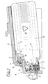
- the reagent bottle 1 shown in FIG. 1 is inserted in the receiving part 2 of a sample analyzer 3 (not shown in detail).
- the reagent bottle 1 has a removal opening 4 and a ventilation opening 5 on the same side, each of which is arranged in a bottle neck-like formation 4 ', 5' of the reagent bottle 1.
- the two axes e and b of the removal opening 4 and the ventilation opening 5 run parallel to one another and form an acute angle with the horizontal, so that the reagent bottle 1 in the inserted state has a removal opening 4 which is inclined downwards and allows emptying with only a small amount of residual liquid .
- the reagent bottle 1 can be inserted into the receiving part 2 of the sample analyzer 3 by a simple linear insertion movement along the axes e or b, with corresponding removal or ventilation elements 8, 13 of the analyzer being inserted into the two openings 4 and 5 in one operation .
- the removal opening 4 is closed by an elastic stopper 6 which is pierced in a first position 7 by an extraction tube 8 of the analyzer and in a second position 9 by an element 10 for measuring the fill level.
- the element for measuring the fill level is designed as a light guide rod 10 ', although other known elements, such as electrodes for measuring the conductivity, can of course also be used as a variant for measuring the fill level.
- the ventilation opening 5 is covered with a film 11 which, when inserted, is pierced by a piercing mandrel 13 having a plurality of ribs 12.
- the elastic stopper 6 is also covered by a protective film 14, which also covers the upper part of the bottle neck 4 'of the removal opening 4.
- a protective film 14 which also covers the upper part of the bottle neck 4 'of the removal opening 4.
- recesses 15 are provided in both pierceable positions 7 and 9 for better piercing of the film 14.
- Pre-pierced areas 16 adjoin these two recesses 15, which are pierced with a pointed mandrel (diameter 1 to 2 mm) during the insertion process of the stopper 6 into the removal opening 4.
- these areas 16 remain absolutely tight and only serve to facilitate the passage of the sampling tube 8 and the light guide 10 when the reagent bottle 1 is inserted into the analyzer.
- the areas 16 are adjoined by conical sealing surfaces 17, which tightly enclose the extraction tube 8 and the light guide rod 10 '.
- the latter In order to better withstand the stresses when piercing the stopper 6, the latter has a support disk 18 on its inside, which is supported on a projection 19 of the bottle neck 4 '. In the area of the two pierceable positions 7 and 9, the support disk 18 has openings 20 which are penetrated by the light guide rod 10 ′ and the removal tube 8 when the reagent bottle 1 is inserted into the analyzer.
- FIG. 5 shows a plan view of the support disk 18 according to arrow V in FIG. 4
- FIG. 6 shows a section according to FIG. 4
- FIG. 7 shows a section along the line VII-VII in FIG. 5.
- the support disk 18 has on one side cylindrical extensions 35 for anchoring in the elastic plug 6 and is reinforced on the other side by stiffening ribs 36. Furthermore, the support disc has guide elements 37 for handling it in the bottling plant.
- the bottle neck 4' of the removal opening 4 has an extension 21 for receiving air bubbles which are introduced into the reagent bottle 1 when the light guide rod is inserted and which could interfere with the optical measurement. Any air bubbles can rise into extension 21.
- the reagent bottle 1 has a recessed grip 24 on each of two opposite side surfaces 22, 23, which reduces the bottle cross-section in the region of the recessed grip and increases the dimensional stability of the reagent bottle 1.
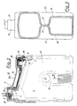
- Empty reagent bottles can also be used as waste containers in the sample analyzer 3, as can be seen from FIG. 2.
- the empty reagent bottle is removed from the analyzer, the elastic stopper in the regions 16 closing again due to elastic deformation.
- the reagent bottle can then be inserted into a receiving part 25 of the analyzer 3, the elastic stopper 6 in the removal opening 4 being pierced by a connecting line 26 to a vacuum pump (not shown).
- an indentation 27 is provided approximately in the middle of two opposite side surfaces 22, 23, which supports the two side surfaces 22, 23 against each other.
- a sealing element 28 is inserted into the ventilation opening 5.
- a unit 29 is inserted into the ventilation opening 5, which has a feed line 30 for the liquid and gaseous media occurring in the analyzer and an element 31 for level measurement.
- This element can also be designed as a light guide rod.
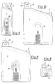
- FIGS. 8 to 11 A set of such bottles is shown in FIGS. 8 to 11, FIG. 8 showing a 25 ml vial, FIG. 9 showing a 100 ml vial, FIG. 10 showing a 500 ml vial and FIG. 11 showing an 800 ml vial.
- the largest bottle of this set the one shown in FIG 800ml bottle, can be used as a waste bottle after emptying.
- the reagent bottles in FIGS. 8 to 11 show on the bottle neck 4 'of the removal opening 4 on the outside a circumferential annular groove 32 (FIG. 8) or two opposite indentations 33. These serve to hold the reagent bottles in a filling system.
Landscapes
- Engineering & Computer Science (AREA)
- Mechanical Engineering (AREA)
- Immunology (AREA)
- Pathology (AREA)
- Analytical Chemistry (AREA)
- Biochemistry (AREA)
- General Health & Medical Sciences (AREA)
- General Physics & Mathematics (AREA)
- Physics & Mathematics (AREA)
- Chemical & Material Sciences (AREA)
- Life Sciences & Earth Sciences (AREA)
- Health & Medical Sciences (AREA)
- Ceramic Engineering (AREA)
- Automatic Analysis And Handling Materials Therefor (AREA)
- Medical Preparation Storing Or Oral Administration Devices (AREA)
- Investigating Or Analysing Biological Materials (AREA)
- Sampling And Sample Adjustment (AREA)
Applications Claiming Priority (3)
| Application Number | Priority Date | Filing Date | Title |
|---|---|---|---|
| AT120395 | 1995-07-14 | ||
| AT1203/95 | 1995-07-14 | ||
| AT0120395A AT406913B (de) | 1995-07-14 | 1995-07-14 | In einen probenanalysator einsetzbare reagenzienflaschen |
Publications (3)
| Publication Number | Publication Date |
|---|---|
| EP0753746A2 true EP0753746A2 (fr) | 1997-01-15 |
| EP0753746A3 EP0753746A3 (fr) | 1998-06-10 |
| EP0753746B1 EP0753746B1 (fr) | 2000-10-18 |
Family
ID=3508852
Family Applications (1)
| Application Number | Title | Priority Date | Filing Date |
|---|---|---|---|
| EP96890113A Expired - Lifetime EP0753746B1 (fr) | 1995-07-14 | 1996-07-01 | Récipient pour réactif intégrable dans un analyseur |
Country Status (5)
| Country | Link |
|---|---|
| US (1) | US5683658A (fr) |
| EP (1) | EP0753746B1 (fr) |
| JP (1) | JP2967153B2 (fr) |
| AT (1) | AT406913B (fr) |
| DE (1) | DE59606006D1 (fr) |
Cited By (4)
| Publication number | Priority date | Publication date | Assignee | Title |
|---|---|---|---|---|
| DE19837434C2 (de) * | 1997-08-20 | 2001-05-17 | Hitachi Ltd | Automatische chemische Analyseeinrichtung |
| DE19849591C2 (de) * | 1997-10-27 | 2001-07-19 | Hitachi Ltd | Automatisches Analysegerät |
| DE19737173B4 (de) * | 1997-08-26 | 2007-04-05 | Eppendorf Ag | Mikrodosiersystem |
| DE102005057191B4 (de) * | 2005-11-29 | 2011-12-08 | Leica Biosystems Nussloch Gmbh | Gewebeprozessor |
Families Citing this family (16)
| Publication number | Priority date | Publication date | Assignee | Title |
|---|---|---|---|---|
| USD433149S (en) * | 1998-03-27 | 2000-10-31 | Roche Diagnostics Corporation | Reagent kit |
| EP1225450A1 (fr) * | 2001-01-02 | 2002-07-24 | Randox Laboratories Ltd. | Appareil de distribution ou de remplissage en réactif, et récipient à réactif |
| IL141111A0 (en) * | 2001-01-25 | 2002-02-10 | Biopreventive Ltd | Reaction vessel and system incorporating same |
| USD482793S1 (en) | 2001-09-11 | 2003-11-25 | Sysmex Corporation | Vessel |
| JP4839417B2 (ja) * | 2003-11-19 | 2011-12-21 | ウイリアム エー クック オーストラリア ピィティワイ リミテッド | 吸引装置用の栓 |
| US7731414B2 (en) * | 2007-02-08 | 2010-06-08 | Instrumentation Laboratory Company | Reagent cartridge mixing tube |
| CN105759019B (zh) * | 2010-02-26 | 2019-05-31 | 希森美康株式会社 | 试剂容器以及试剂容器组件 |
| USD718871S1 (en) * | 2011-08-03 | 2014-12-02 | Roche Diagnostics International Ag | Cartridge filling device |
| CA2931609A1 (fr) | 2013-12-04 | 2015-06-11 | Pocared Diagnostics Ltd. | Agencement de filtre avec robinet a curseur et son procede d'utilisation |
| GB2524004A (en) * | 2014-03-10 | 2015-09-16 | Stratec Biomedical Ag | Dispenser |
| US12442829B2 (en) | 2015-05-01 | 2025-10-14 | Abbott Laboratories | Containers and caps having ket rings for enabling removal of liquid contents of a container |
| EP3289366B1 (fr) | 2015-05-01 | 2021-12-29 | Abbott Laboratories | Appareil pour retirer un contenu liquide présent dans un récipient |
| USD1105913S1 (en) | 2016-04-28 | 2025-12-16 | Abbott Laboratories | Bottle cap |
| DE102017005835B4 (de) * | 2017-06-20 | 2020-04-02 | Diehl Metering Gmbh | Vorrichtung zur mobilen Bestimmung einer Eigenschaft einer flüssigen, festen oder gasförmigen Probe |
| CN111065904A (zh) | 2017-08-02 | 2020-04-24 | 普凯尔德诊断技术有限公司 | 包括通过过滤器去除废液的方法和装置的处理器过滤器布置 |
| AU201817586S (en) * | 2018-12-17 | 2019-01-21 | Leica Biosystems Melbourne Pty | A reagent container |
Family Cites Families (18)
| Publication number | Priority date | Publication date | Assignee | Title |
|---|---|---|---|---|
| FR1115785A (fr) * | 1954-12-06 | 1956-04-30 | Bouchon pour flacons ou analogues | |
| US3630418A (en) * | 1970-02-11 | 1971-12-28 | Technicon Instr | Dispenser for supplying liquid by suction |
| US4046610A (en) * | 1974-10-07 | 1977-09-06 | Lilja Duane F | Fluid product reservoir and method |
| US4163500A (en) * | 1978-01-23 | 1979-08-07 | Siemens Aktiengesellschaft | Bottle seal |
| US4243150A (en) * | 1978-01-23 | 1981-01-06 | Siemens Aktiengesellschaft | Bottle seal |
| US4381776A (en) * | 1980-06-20 | 1983-05-03 | Haemonetics Corporation | Anticoagulant dispensing apparatus and method of use |
| JPS57158551A (en) * | 1981-03-27 | 1982-09-30 | Hitachi Ltd | Automatic liquid sampler |
| US4844870A (en) * | 1987-07-17 | 1989-07-04 | Fisher Scientific Company | Liquid monitoring |
| GB2208227A (en) * | 1988-08-11 | 1989-03-15 | Ici Plc | Introducing additive into a container |
| US5125522A (en) * | 1988-12-22 | 1992-06-30 | Abbott Laboratories | Enteral delivery set assembly |
| GB8914456D0 (en) * | 1989-06-23 | 1989-08-09 | Radiometer As | Apparatus for analysis of samples of fluids |
| DE3938559A1 (de) * | 1989-11-21 | 1991-05-23 | Boehringer Mannheim Gmbh | Reagenzbevorratungssystem fuer ein medizinisches analysegeraet |
| FR2663291A1 (fr) * | 1990-06-15 | 1991-12-20 | Oreal | Procede pour le conditionnement d'un produit dans un flacon, permettant d'assurer une meilleure conservation du produit au cours du stockage et ensemble de conditionnement correspondant. |
| JP3030881B2 (ja) * | 1991-01-30 | 2000-04-10 | セイコーエプソン株式会社 | インクジェット記録装置 |
| US5419316A (en) * | 1991-08-21 | 1995-05-30 | Bernstein; Jerome | Anesthesia evaporators |
| US5213967A (en) * | 1992-02-25 | 1993-05-25 | Merck & Co., Inc. | Automated sterility testing system with concurrent sample dissolving, diluting and mixing |
| US5334178A (en) * | 1993-04-14 | 1994-08-02 | Habley Medical Technology Corporation | Pierceable pharmaceutical container closure with check valve |
| US5472112A (en) * | 1994-10-31 | 1995-12-05 | The United States Of America As Represented By The Secretary Of The Navy | Quick-pour container |
-
1995
- 1995-07-14 AT AT0120395A patent/AT406913B/de not_active IP Right Cessation
-
1996
- 1996-06-26 US US08/670,433 patent/US5683658A/en not_active Expired - Lifetime
- 1996-07-01 EP EP96890113A patent/EP0753746B1/fr not_active Expired - Lifetime
- 1996-07-01 DE DE59606006T patent/DE59606006D1/de not_active Expired - Lifetime
- 1996-07-11 JP JP8181062A patent/JP2967153B2/ja not_active Expired - Fee Related
Cited By (5)
| Publication number | Priority date | Publication date | Assignee | Title |
|---|---|---|---|---|
| DE19837434C2 (de) * | 1997-08-20 | 2001-05-17 | Hitachi Ltd | Automatische chemische Analyseeinrichtung |
| US6599477B1 (en) | 1997-08-20 | 2003-07-29 | Hitachi, Ltd. | Chemical analysis apparatus |
| DE19737173B4 (de) * | 1997-08-26 | 2007-04-05 | Eppendorf Ag | Mikrodosiersystem |
| DE19849591C2 (de) * | 1997-10-27 | 2001-07-19 | Hitachi Ltd | Automatisches Analysegerät |
| DE102005057191B4 (de) * | 2005-11-29 | 2011-12-08 | Leica Biosystems Nussloch Gmbh | Gewebeprozessor |
Also Published As
| Publication number | Publication date |
|---|---|
| EP0753746B1 (fr) | 2000-10-18 |
| DE59606006D1 (de) | 2000-11-23 |
| JP2967153B2 (ja) | 1999-10-25 |
| JPH0949844A (ja) | 1997-02-18 |
| ATA120395A (de) | 2000-02-15 |
| US5683658A (en) | 1997-11-04 |
| AT406913B (de) | 2000-10-25 |
| EP0753746A3 (fr) | 1998-06-10 |
Similar Documents
| Publication | Publication Date | Title |
|---|---|---|
| AT406913B (de) | In einen probenanalysator einsetzbare reagenzienflaschen | |
| DE60212522T2 (de) | Vorrichtung für die Entnahme von flüssigen Proben | |
| DE69810554T2 (de) | Kugelgelenkverschluss mit integraler flexibler Dichtung für Probenaufnahmebehälter | |
| DE69917386T2 (de) | Mikroplattenaufbau und Verschluss | |
| DE60210891T2 (de) | Geschlossene Mikroplatten | |
| EP0431352B1 (fr) | Système d'alimentation en réactifs pour analyseur clinique | |
| DE60031526T2 (de) | Durchdringbare kappe mit innerer spitze | |
| DE69212712T2 (de) | Kapillarisches Röhrchen mit einer Entlüftungskappe | |
| DE19746169A1 (de) | Kappe für einen Reagenzbehälter | |
| EP0951939A2 (fr) | Dispositif de stockage d'éléments d'analyse | |
| EP0872279B1 (fr) | Dispositif de dosage pour delivrer de petites quantités de liquide | |
| DE69828122T2 (de) | Kugelgelenkverschluss für Probenaufnahmebehälter | |
| CN103459036B (zh) | 用于密封容器的盖 | |
| CA2083489A1 (fr) | Methode et appareil pour prelever a la pipette un liquide dans un contenant hermetique | |
| EP1981637A1 (fr) | Récipient d'échantillonnage servant à contenir de petites quantités de liquide pour analyses | |
| DE69033868T2 (de) | Gerät zur Analyse von Flüssigkeitsproben | |
| EP0853495B1 (fr) | Usage de recipients pour liquides | |
| EP1934574B1 (fr) | Systeme de prelevement d'echantillons pour des echantillons fluides | |
| DE4306821A1 (de) | Vorrichtung zum Umfüllen einer Lösung zwischen abgedichteten Behältern | |
| DE102009043226A1 (de) | Flachkörper nach Art einer Chip-Karte zur biochemischen Analyse und Verfahren zu dessen Verwendung | |
| JPH07167754A (ja) | 容 器 | |
| DE69111394T2 (de) | Einwegvorrichtung zur Prüfung einer Flüssigkeit. | |
| EP3502005B1 (fr) | Élément de fermeture pourvu d'ouverture d'aération | |
| DE69103437T2 (de) | Vorrichtung zum automatischen Verschliessen einer Pipettenspitze. | |
| CH615589A5 (en) | Device for preparing and mixing medical nutrient solutions for the intravenous alimentation of patients |
Legal Events
| Date | Code | Title | Description |
|---|---|---|---|
| PUAI | Public reference made under article 153(3) epc to a published international application that has entered the european phase |
Free format text: ORIGINAL CODE: 0009012 |
|
| AK | Designated contracting states |
Kind code of ref document: A2 Designated state(s): DE FR GB |
|
| PUAL | Search report despatched |
Free format text: ORIGINAL CODE: 0009013 |
|
| AK | Designated contracting states |
Kind code of ref document: A3 Designated state(s): DE FR GB |
|
| 17P | Request for examination filed |
Effective date: 19980730 |
|
| 17Q | First examination report despatched |
Effective date: 19990609 |
|
| GRAG | Despatch of communication of intention to grant |
Free format text: ORIGINAL CODE: EPIDOS AGRA |
|
| GRAG | Despatch of communication of intention to grant |
Free format text: ORIGINAL CODE: EPIDOS AGRA |
|
| GRAH | Despatch of communication of intention to grant a patent |
Free format text: ORIGINAL CODE: EPIDOS IGRA |
|
| GRAH | Despatch of communication of intention to grant a patent |
Free format text: ORIGINAL CODE: EPIDOS IGRA |
|
| GRAA | (expected) grant |
Free format text: ORIGINAL CODE: 0009210 |
|
| AK | Designated contracting states |
Kind code of ref document: B1 Designated state(s): DE FR GB |
|
| ET | Fr: translation filed | ||
| GBT | Gb: translation of ep patent filed (gb section 77(6)(a)/1977) |
Effective date: 20001026 |
|
| REF | Corresponds to: |
Ref document number: 59606006 Country of ref document: DE Date of ref document: 20001123 |
|
| PLBE | No opposition filed within time limit |
Free format text: ORIGINAL CODE: 0009261 |
|
| STAA | Information on the status of an ep patent application or granted ep patent |
Free format text: STATUS: NO OPPOSITION FILED WITHIN TIME LIMIT |
|
| 26N | No opposition filed | ||
| REG | Reference to a national code |
Ref country code: GB Ref legal event code: IF02 |
|
| PGFP | Annual fee paid to national office [announced via postgrant information from national office to epo] |
Ref country code: GB Payment date: 20140624 Year of fee payment: 19 |
|
| PGFP | Annual fee paid to national office [announced via postgrant information from national office to epo] |
Ref country code: DE Payment date: 20140731 Year of fee payment: 19 |
|
| PGFP | Annual fee paid to national office [announced via postgrant information from national office to epo] |
Ref country code: FR Payment date: 20140624 Year of fee payment: 19 |
|
| REG | Reference to a national code |
Ref country code: DE Ref legal event code: R119 Ref document number: 59606006 Country of ref document: DE |
|
| GBPC | Gb: european patent ceased through non-payment of renewal fee |
Effective date: 20150701 |
|
| PG25 | Lapsed in a contracting state [announced via postgrant information from national office to epo] |
Ref country code: DE Free format text: LAPSE BECAUSE OF NON-PAYMENT OF DUE FEES Effective date: 20160202 Ref country code: GB Free format text: LAPSE BECAUSE OF NON-PAYMENT OF DUE FEES Effective date: 20150701 |
|
| REG | Reference to a national code |
Ref country code: FR Ref legal event code: ST Effective date: 20160331 |
|
| PG25 | Lapsed in a contracting state [announced via postgrant information from national office to epo] |
Ref country code: FR Free format text: LAPSE BECAUSE OF NON-PAYMENT OF DUE FEES Effective date: 20150731 |