EP0754143B1 - Künstlicher satellit mit aerodynamischen und magnetischen drehmomentgebern und steuerungsverfahren für einen derartigen satelliten - Google Patents
Künstlicher satellit mit aerodynamischen und magnetischen drehmomentgebern und steuerungsverfahren für einen derartigen satelliten Download PDFInfo
- Publication number
- EP0754143B1 EP0754143B1 EP95915219A EP95915219A EP0754143B1 EP 0754143 B1 EP0754143 B1 EP 0754143B1 EP 95915219 A EP95915219 A EP 95915219A EP 95915219 A EP95915219 A EP 95915219A EP 0754143 B1 EP0754143 B1 EP 0754143B1
- Authority
- EP
- European Patent Office
- Prior art keywords
- satellite
- panels
- sin
- moments
- magnetic
- Prior art date
- Legal status (The legal status is an assumption and is not a legal conclusion. Google has not performed a legal analysis and makes no representation as to the accuracy of the status listed.)
- Expired - Lifetime
Links
- 230000005291 magnetic effect Effects 0.000 title claims description 57
- 238000000034 method Methods 0.000 title claims description 11
- 238000005096 rolling process Methods 0.000 claims description 3
- 238000006073 displacement reaction Methods 0.000 claims 1
- 238000009432 framing Methods 0.000 claims 1
- 239000007789 gas Substances 0.000 description 5
- 239000013598 vector Substances 0.000 description 4
- 230000007935 neutral effect Effects 0.000 description 3
- 230000001174 ascending effect Effects 0.000 description 2
- 239000000969 carrier Substances 0.000 description 2
- 230000015556 catabolic process Effects 0.000 description 2
- 230000000694 effects Effects 0.000 description 2
- 239000003380 propellant Substances 0.000 description 2
- 238000004804 winding Methods 0.000 description 2
- WGLPBDUCMAPZCE-UHFFFAOYSA-N Trioxochromium Chemical compound O=[Cr](=O)=O WGLPBDUCMAPZCE-UHFFFAOYSA-N 0.000 description 1
- QVGXLLKOCUKJST-UHFFFAOYSA-N atomic oxygen Chemical compound [O] QVGXLLKOCUKJST-UHFFFAOYSA-N 0.000 description 1
- 230000009286 beneficial effect Effects 0.000 description 1
- 230000005540 biological transmission Effects 0.000 description 1
- 238000006243 chemical reaction Methods 0.000 description 1
- 229910000423 chromium oxide Inorganic materials 0.000 description 1
- 150000001875 compounds Chemical class 0.000 description 1
- 230000001276 controlling effect Effects 0.000 description 1
- 238000012937 correction Methods 0.000 description 1
- 230000007797 corrosion Effects 0.000 description 1
- 238000005260 corrosion Methods 0.000 description 1
- 230000007547 defect Effects 0.000 description 1
- 230000005294 ferromagnetic effect Effects 0.000 description 1
- 239000000446 fuel Substances 0.000 description 1
- 238000002955 isolation Methods 0.000 description 1
- 238000005259 measurement Methods 0.000 description 1
- 239000002245 particle Substances 0.000 description 1
- 230000001105 regulatory effect Effects 0.000 description 1
- 230000035939 shock Effects 0.000 description 1
- 238000006467 substitution reaction Methods 0.000 description 1
- 239000013589 supplement Substances 0.000 description 1
Images




Classifications
-
- B—PERFORMING OPERATIONS; TRANSPORTING
- B64—AIRCRAFT; AVIATION; COSMONAUTICS
- B64G—COSMONAUTICS; VEHICLES OR EQUIPMENT THEREFOR
- B64G1/00—Cosmonautic vehicles
- B64G1/22—Parts of, or equipment specially adapted for fitting in or to, cosmonautic vehicles
- B64G1/24—Guiding or controlling apparatus, e.g. for attitude control
- B64G1/32—Guiding or controlling apparatus, e.g. for attitude control using earth's magnetic field
-
- B—PERFORMING OPERATIONS; TRANSPORTING
- B64—AIRCRAFT; AVIATION; COSMONAUTICS
- B64G—COSMONAUTICS; VEHICLES OR EQUIPMENT THEREFOR
- B64G1/00—Cosmonautic vehicles
- B64G1/22—Parts of, or equipment specially adapted for fitting in or to, cosmonautic vehicles
- B64G1/24—Guiding or controlling apparatus, e.g. for attitude control
- B64G1/244—Spacecraft control systems
-
- B—PERFORMING OPERATIONS; TRANSPORTING
- B64—AIRCRAFT; AVIATION; COSMONAUTICS
- B64G—COSMONAUTICS; VEHICLES OR EQUIPMENT THEREFOR
- B64G1/00—Cosmonautic vehicles
- B64G1/22—Parts of, or equipment specially adapted for fitting in or to, cosmonautic vehicles
- B64G1/24—Guiding or controlling apparatus, e.g. for attitude control
- B64G1/36—Guiding or controlling apparatus, e.g. for attitude control using sensors, e.g. sun-sensors, horizon sensors
- B64G1/366—Guiding or controlling apparatus, e.g. for attitude control using sensors, e.g. sun-sensors, horizon sensors using magnetometers
Definitions
- the invention relates to a satellite artificial equipped with means for creating moments both magnetic and aerodynamic in origin, and a method of controlling such a satellite.
- the aerodynamic control surfaces present the advantage of saving on-board propellant compared to propellants or the like used usually to move and orient satellites, but they still consume them, directly to move them and indirectly to compensate for the trolling effects they cause. That is why, while appreciating these means, we can want to reduce their number or save their jobs.
- the guiding idea of the invention therefore consists in combining the aerodynamic control surfaces with other means, which are magneto-couplers or generators of magnetic couples supplied with renewable energy by photovoltaic cells and having the ability to produce moments of rotation.
- other means which are magneto-couplers or generators of magnetic couples supplied with renewable energy by photovoltaic cells and having the ability to produce moments of rotation.
- an ambient magnetic field such as the earth's magnetic field, according to the formula or is a couple in newton meters, a magnetic moment in ampere turns / square meters and is a magnetic field in tesla.
- a negative consequence of this formula is that the couples around the direction of the ambient magnetic field cannot be produced. It is for this reason in particular that aerodynamic control surfaces will be used although they can also be used as means of complementing magnetic couples produced around other axes.
- the aerodynamic control surfaces will produce couples and rotations around two of the axes of the satellite, whose orientation will be chosen according to the position of the orbit by relation to the magnetic field of the Earth or the planet considered. Magnetic couplers will produce moments around the three main axes from the satellite.
- the referral system will then provided with competing means, but which will not be superfluous because the satellite traversing the orbit and headed in an unchanging direction will never be at a fixed orientation relative to the direction of the field so the magnetic couplers will all useful in turn, and it is so beneficial to resort to them that we will do it preferably to even if the effect of some is weak.
- the invention relates under its most generally forms an artificial satellite, characterized in that it includes generators magnetic moments of rotation around of three main axes of the satellite, and panels rotating exteriors to provide moments aerodynamics of rotation around two axes main depending on the type of satellite and orbit of the satellite according to control laws associating the magnetic generators and the panels to make them produce variable moments; and she is also relating to a method usable for such a satellite orbiting a planet and plunged into a atmosphere and a magnetic field, characterized in that it consists in periodically measuring or estimating the magnetic field of the planet with respect to the axes main points of the satellite and to calculate moments of rotation to be produced around the main axes by the magnetic generators and exterior panels.
- Figure 1 shows couplers magnetic 1, 2 and 3 all similar in their constitution and compounds of a ferromagnetic core 4 cylindrical around which two electric coils 5 and 6 wind their turns. Windings 5 and 6 are connected to batteries 7 themselves supplied by 8 photovoltaic cells lining the panels exposed to the Sun from the satellite. Couplers 1, 2 and 3 have their 4 oriented cores respectively along three main axes of satellite, X, Y and Z, all perpendicular to each other.
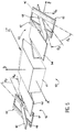
- FIG. 2 There is shown in Figure 2 a satellite 10A carrying magnetic couplers 1, 2 and 3, which will be assumed to be housed in a central body 11 of the satellite 10A from which two masts 12 and 13 protrude which are deployed when the 10A satellite is released from the launch rocket and put into orbit.
- Masts 12 and 13 are similar, aligned and located on both sides of the central body 11, and they carry away from this one a solar panel 14, carrying cells photovoltaic 8 mentioned above, then a control surface aerodynamics 15 composed of a central panel 16 and two extreme panels 17 and 18 which frame the previous.
- the extreme panels 17 and 18 are actually half-panels rotating in unison around an axis in the extension of masts 12 and 13 and which corresponds here at the pitch axis Y of satellite 10A, and the central panel 16 rotates around the same axis regardless of the previous ones.
- the axis of rotation is materialized by hollow trees carrying the panels and rotating in a fixed support shaft pointing from the end of the solar panel 14. This mechanical system simple is shown in figure 7.
- the fixed shaft bears the reference 25, the hollow panel shafts 16 at 18 the references 26 to 28 respectively; we design by 29 the rods which connect the end panels 17 and 18 between them, beyond the edges of the central panel 16; by 30 the bearings which allow the hollow trees 26 and 28 to be carried by the hollow shaft 29; by 31 the bearings which allow the hollow shaft 27 to be carried by the hollow shaft 26; and by 32 and 33 the electric motor and transmission systems which move the hollow shafts 26 and 27 respectively and therefore independently rotate the central panel 16 and the extreme panels 17 and 18 respectively, in supported by the solar panel 14.
- control panels 16 to 18 are symmetrically arranged on the other of the masts 12 and 13 while having dimensions identical to their counterparts and being driven by systems independent of the previous ones.
- the panels central 16 have an area equal to the sum of that extreme panels 17 and 18.
- the satellite 10A traverses an orbit A to which the roll axis X is tangent and oriented in the opposite direction to the path of the satellite.
- the yaw axis Z belongs to the plane of orbit A and is opposite to the direction T of the center of the Earth.
- the pitch axis Y is therefore perpendicular to the plane of orbit A, as well as the masts 12 and 13, and directed to make the coordinate system X, Y and Z direct.
- orbit A is a sun-synchronous orbit at 12 and 24 local hours, which passes almost above the poles of the Earth because the orbital plane makes an angle of about 100 ° with the equatorial plane. Earth's magnetic field is then almost parallel to the orbital plane, to about 20 °. This result is valid for all quasi-polar orbits.
- a roll rotation around the X axis can be controlled by changing the orientation of the central panel 16 or of the panels extremes 17 and 18, as desired, from one of the masts 12 and 13 and by imposing a corresponding rotation in direction opposite similar panels on the other mast 13 or 12, from the neutral position where all the panels extend in a plane parallel to that which is tangent to orbit 1.
- the increase in resistance to the rarefied air which is thus produced results in forces directed along the yaw axis Z, offset in opposite directions and whose value depends on the importance of the tilt.
- Drag forces along the axis X rolls are also produced, which do not create moment because they are equal and in the same direction but brake the 10A satellite and require the use of energy to keep it at the desired speed, which explains that we prefer not to abuse this means.
- the control panels 16, 17 and 18 from one of the masts 12 and 13 of equal angles in opposite directions from the neutral position of these panels (in the plane of orbit A) a rotation around the yaw axis Z is produced because the satellite is braked on the side of this mast 12 or 13 only, and no other rotation is produced because the central panel 16 has an area equal to the area total of the extreme panels 17 and 18, so that the forces oriented in the yaw axis Z cancel each other out.
- the aerodynamic control surfaces 15 therefore make it possible to communicate roll and yaw rotations to 10A satellite. Pitch rotations will be ensured by magnetic couplers only, which is always possible since the pitch axis 10 remains almost perpendicular to the direction of the field Earth magnetic B, whatever the position of the 10A satellite in orbit A. Magnetic couplers 1, 2 and 3 can also exercise rolling moments and lace of variable value according to the position of the satellite 10A: the magnetic yaw moment will be almost zero above the poles, the moment of almost zero roll at ascending and descending nodes from orbit A, and the two moments will be better distributed at intermediate latitudes; the action of aerodynamic control surfaces 15 will supplement the moments magnetic failures.
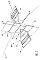
- FIG. 3 represents a 10B satellite equipped to traverse a Sun-synchronous orbit at 6 a.m. and 6 p.m. local.
- Orbit B is still almost polar and at one inclination of approximately 100 ° on the equatorial plane.
- the situation is not fundamentally different from the previous, and we find a central body 11 of which stand masts 12 and 13 carrying rudders aerodynamics similar to the previous ones to ensure the roll and yaw movements of the 10B satellite.
- the main difference consists of masts additional 19 and 20 carriers of solar panels 21 replacing solar panels 14.
- Masts additional 19 and 20 extend along the axis of yaw Z and the solar panels 21 are oriented in the direction of the pitch axis Y and towards the Sun, whose direction is almost perpendicular to that of the orbital plane, unlike the realization former.
- the satellite 10B includes masts 12, 13, 19 and 20 identical to the previous achievement, i.e. carriers of control panels 16, 17 and 18 only for some, and solar panels 21 for others.
- the control panels 16, 17 and 18 extend along yaw axis Z and are directed in the pitch axis Y, while the reverse is true for solar panels 21.
- the aerodynamic control surfaces 15 allow here to produce moments around the pitch axis Y and the axis of roll X by tilting them in the same way as in previous achievements. For this last axis, there will therefore have competition from both means guidance, which will be resolved using primarily the magnetic coupler, for the reasons already mentioned fuel saving.
- an on-board computer responsible for regulating the supply of current to the magnetic couplers 1, 2 and 3 and to the motors 32 and 33, and which operates with software which calculates at any time the orientation of the terrestrial magnetic field. with respect to the satellite 10.
- the satellite may include a magnetometer which provides this measurement, but it is still possible to model the direction of the magnetic field according to its components with respect to the main axes of the satellite 10 as a function of time, c ' that is to say the course of the orbit. It is assumed that no significant defect in orientation appears and that the roll, pitch and yaw axes remain tangent to the orbit and at invariable positions relative to the orbit.
- Total torque produced on satellite 10 is the vector sum of the magnetic torque and the aerodynamic torque. This equation can be broken down on each of the axes and, as already mentioned, the aerodynamic torque Ay around the pitch axis Y is zero, i.e. As in addition we want the overall value of the aerodynamic torque to be as small as possible, it is desirable that the vectors VS A and VS M are perpendicular, and we deduce the following relations which finally give MX MZ :
- the magnetic couplers 1, 2 and 3 whose cores 4 are aligned with the axes X, Y and Z respectively produce the magnetic moments x , y z .
- central panels 16 have an area equal to that of the sum of the panels extremes 17 and 18 of the same mast 12 or 13. This surface is denoted S / 2, and l denotes the distance between the center of inertia of satellite 10 and the center of the panel central 16.
- the aerodynamic control surfaces 15 can be assigned to the braking of the satellite 10 and therefore to certain orbit corrections. Just get to produce zero aerodynamic moments and a total drag force proportional to
- control laws given here can be easily modified to suit others forms of orbit.
- arrangement of the control surfaces given here allows the satellite to be used for all the inclinations of low orbit.
Landscapes
- Engineering & Computer Science (AREA)
- Remote Sensing (AREA)
- Chemical & Material Sciences (AREA)
- Combustion & Propulsion (AREA)
- Radar, Positioning & Navigation (AREA)
- Aviation & Aerospace Engineering (AREA)
- Life Sciences & Earth Sciences (AREA)
- Environmental & Geological Engineering (AREA)
- General Life Sciences & Earth Sciences (AREA)
- Geochemistry & Mineralogy (AREA)
- Geology (AREA)
- Automation & Control Theory (AREA)
- Control Of Position, Course, Altitude, Or Attitude Of Moving Bodies (AREA)
Claims (11)
- Künstlicher Satellit mit magnetischen Drehmomentgebern (1, 2, 3) um drei Hauptachsen (X, Y, Z) des Satelliten herum,
dadurch gekennzeichnet,
daß er dreh- bzw. schwenkbare Außentafeln bzw. -panels (16, 17, 18) umfaßt, um aerodynamische Momente um zwei der drei Hauptachsen (X,Z oder X,Y) zu liefern, je nach Satellitentyp und Satellitenumlaufbahn, in Abhängigkeit von Steuergesetzen, welche die magnetischen Geber und die Panels verbinden, damit sie variable Momente erzeugen. - Künstlicher Satellit nach Anspruch 1, dadurch gekennzeichnet, daß die Außenpanels zwei Paare umfassen und symmetrisch angeordnet sind in bezug auf ein Trägheitszentrum des Satelliten.
- Künstlicher Satellit nach Anspruch 2, dadurch gekennzeichnet, daß die Außenpanels zwei Paare umfassen und sich um im wesentlichen fluchtende Achsen drehen.
- Künstlicher Satellit nach Anspruch 3, dadurch gekennzeichnet, daß die Panels jedes Paars eine identische Fläche haben und gebildet werden durch ein zentrales Panel (16) und zwei identische Halbpanel (17, 18), die aus einem Stück sind und das zentrale Panel umrahmen.
- Verfahren zum Steuern eines künstlichen Satelliten nach Anspruch 1, der sich im Orbit um einen Planeten und in einer Atmosphäre und einem Magnetfeld befindet,
dadurch gekennzeichnet,
daß es darin besteht, periodisch das Magnetfeld (B) des Planeten in bezug auf die Hauptachsen des Satelliten zu messen und durch die magnetischen Geber und die Außenpanels um die Hauptachsen herum zu erzeugende Drehmomente zu berechnen. - Verfahren zum Steuern eines künstlichen Satelliten nach Anspruch 5, dadurch gekennzeichnet, daß es darin besteht, Drehmomente zu berechnen und durch die magnetischen Geber zu erzeugen, bei denen die durch die Außenpanels erzeugten Drehmomente einen minimalen Gesamtwert haben.
- Verfahren zum Steuern eines künstlichen Satelliten nach Anspruch 5, dadurch gekennzeichnet, daß der Satellit eine quasipolare Umlaufbahn durchläuft, und dadurch, daß die durch die Außenpanels erzeugten Drehmomente Roll- und Giermomente sind.
- Verfahren zum Steuern eines künstlichen Satelliten nach Anspruch 5, dadurch gekennzeichnet, daß der Satellit eine äquatoriale Umlaufbahn durchläuft und die durch die Außenpanels erzeugten Momente Nick- und Rollmomente sind.
- Verfahren zum Steuern eines künstlichen Satelliten nach Anspruch 5, dadurch gekennzeichnet, daß die Außenpanels gesteuert werden, um die durch die Atmosphäre erzeugten Luftwiderstandskräfte zu minimieren.
- Verfahren zum Steuern eines künstlichen Satelliten nach Anspruch 6, dadurch gekennzeichnet, daß die magnetischen Momente (M) erzeugt werden nach den Formeln
 wo x, y und z die Hauptachsen des Satelliten bezeichnen,Bx, By, und Bz die Komponenten des Umgebungsmagnetfelds
B entsprechend den Hauptachsen bezeichnen, im Satelliten erzeugt durch die magnetischen Geber und die Panels entsprechend den Hauptachsen, undCx,Cy und Cz die Komponenten des GesamtmomentsC bezeichnen, im Satelliten erzeugt durch die magnetischen Geber und die Panels entsprechend den Hauptachsen, undwo - Verfahren zum Steuern eines künstlichen Satelliten nach den Ansprüchen 9 und 10, dadurch gekennzeichnet, daß die Außenpanels den folgenden Formeln entsprechend gesteuert werden, wenn der Satellit vier Außenpanels aufweist, flächengleich und paarweise symmetrisch angeordnet, indem sie Winkel 1 bis 4 mit einer Fortbewegungsrichtung des Satelliten bilden, wobei die Panels des einen Paars die Winkel 1 und 2 und die des anderen Paars die Winkel 3 und 4 bilden und die Panels, die einerseits die Winkel 1 und 3 und andererseits die Winkel 2 und 4 bilden, sich seitlich auf derselben Seite des Satelliten befinden, und dadurch, daß man schreibt:1°) Wenn Cax≠0 :a) Wenn Caz≥0 und
und 3=4=0.b) Wenn Caz≥0 und 1≤C2
indem man schreibt
und 1=3=0.c) Wenn Caz≤0 und 0≤C2≤1 mit X wie vorhergehend,
und 3=4=0.d) Wenn Caz≤0 und 1≤C2,
mit α wie vorhergehend,
und2°) Wenn Cax≈0, das heißt mit kleinerem Modul als z.B. 10-4,a) Wenn Caz≥0,b) Wenn Caz≤0,
Applications Claiming Priority (3)
| Application Number | Priority Date | Filing Date | Title |
|---|---|---|---|
| FR9403765 | 1994-03-30 | ||
| FR9403765A FR2718105B1 (fr) | 1994-03-30 | 1994-03-30 | Satellite artificiel muni de générateurs de moments magnétiques et aérodynamiques et procédé de commande d'un tel satellite. |
| PCT/FR1995/000393 WO1995026905A1 (fr) | 1994-03-30 | 1995-03-29 | Satellite artificiel muni de generateurs de moments magnetiques et aerodynamiques et procede de commande d'un tel satellite |
Publications (2)
| Publication Number | Publication Date |
|---|---|
| EP0754143A1 EP0754143A1 (de) | 1997-01-22 |
| EP0754143B1 true EP0754143B1 (de) | 1998-03-04 |
Family
ID=9461593
Family Applications (1)
| Application Number | Title | Priority Date | Filing Date |
|---|---|---|---|
| EP95915219A Expired - Lifetime EP0754143B1 (de) | 1994-03-30 | 1995-03-29 | Künstlicher satellit mit aerodynamischen und magnetischen drehmomentgebern und steuerungsverfahren für einen derartigen satelliten |
Country Status (8)
| Country | Link |
|---|---|
| US (1) | US6371413B1 (de) |
| EP (1) | EP0754143B1 (de) |
| JP (1) | JPH09511471A (de) |
| CN (1) | CN1068282C (de) |
| CA (1) | CA2186472A1 (de) |
| DE (1) | DE69501728T2 (de) |
| FR (1) | FR2718105B1 (de) |
| WO (1) | WO1995026905A1 (de) |
Families Citing this family (22)
| Publication number | Priority date | Publication date | Assignee | Title |
|---|---|---|---|---|
| IL126210A (en) | 1998-07-01 | 2002-12-01 | Israel Aircraft Ind Ltd | Lightweight and low-excitation magnetoturker |
| FR2836450B1 (fr) * | 2002-02-25 | 2004-12-03 | Centre Nat Etd Spatiales | Vehicule spatial et procede de pilotage d'un tel vehicule |
| US6745984B2 (en) * | 2002-04-23 | 2004-06-08 | Astrium Sas | Method of controlling the attitude and stabilization of a satellite in low orbit |
| CN102514736B (zh) * | 2011-11-15 | 2014-12-24 | 上海卫星工程研究所 | 摆动机构控制器 |
| RU2496689C1 (ru) * | 2012-03-29 | 2013-10-27 | Открытое акционерное общество "Информационные спутниковые системы" имени академика М.Ф. Решетнёва" | Способ коррекции орбитального движения космического аппарата |
| RU2535352C2 (ru) * | 2012-06-22 | 2014-12-10 | Открытое акционерное общество "Информационные спутниковые системы" имени академика М.Ф. Решетнёва" | Способ тестирования двигателей коррекции космического аппарата |
| FR2997519B1 (fr) * | 2012-10-30 | 2014-12-12 | Astrium Sas | Procede de commande de magneto-coupleurs d'un systeme de controle d'attitude d'un vehicule spatial |
| RU2558529C2 (ru) * | 2013-10-02 | 2015-08-10 | Акционерное общество "Информационные спутниковые системы" имени академика М.Ф. Решетнёва" | Способ коррекции орбитального движения космического аппарата |
| CN103818566B (zh) * | 2014-03-18 | 2015-10-14 | 西北工业大学 | 一种三轴磁力矩器的模块化制作方法 |
| TWI551513B (zh) * | 2014-03-18 | 2016-10-01 | 國立屏東科技大學 | 減轉裝置 |
| US10036830B2 (en) * | 2014-12-31 | 2018-07-31 | Bae Systems Information And Electronics Systems Integration Inc. | Device and method for making weather observations using infrared spectral radiometry |
| US10647450B2 (en) * | 2016-03-18 | 2020-05-12 | The Boeing Company | Satellite control system using electrically controllable variable reflection glass panels |
| US10590068B2 (en) * | 2016-12-06 | 2020-03-17 | Skeyeon, Inc. | System for producing remote sensing data from near earth orbit |
| US10752385B2 (en) * | 2017-03-09 | 2020-08-25 | Princeton Satellite Systems, Inc. | Magnetic dipole cancellation |
| US20210284361A1 (en) * | 2019-07-17 | 2021-09-16 | Skeyeon, Inc. | Systems and methods for attitude control for a satellite |
| KR102232860B1 (ko) * | 2019-10-15 | 2021-03-26 | 한국항공우주연구원 | 비행체 자세제어 시스템 및 비행체 자세제어방법 |
| CN111232248B (zh) * | 2020-02-14 | 2021-07-27 | 哈尔滨工业大学 | 一种基于轨控推力器脉宽调制的姿轨一体化控制方法 |
| CN113071713B (zh) * | 2021-03-11 | 2022-11-22 | 中国空间技术研究院 | 卫星磁矩的分配方法和装置 |
| WO2024028817A1 (en) * | 2022-08-05 | 2024-02-08 | Zenno Astronautics Limited | An improved satellite system |
| CN116331524B (zh) * | 2023-05-30 | 2023-07-21 | 北京钧天航宇技术有限公司 | 一种卫星磁力矩器安装位置的确定方法及装置 |
| TWI886967B (zh) * | 2024-05-21 | 2025-06-11 | 國立清華大學 | 磁性反作用輪操作方法及磁性反作用輪 |
| JP2026056063A (ja) * | 2024-09-19 | 2026-04-01 | 国立研究開発法人宇宙航空研究開発機構 | 空力装置および衛星 |
Family Cites Families (13)
| Publication number | Priority date | Publication date | Assignee | Title |
|---|---|---|---|---|
| US3116035A (en) * | 1959-10-01 | 1963-12-31 | Bell Telephone Labor Inc | Attitude control of earth satellites |
| US3061239A (en) * | 1960-08-04 | 1962-10-30 | Lockheed Aircraft Corp | Magnetic moment device for applying corrective torque to a space vehicle |
| US3162764A (en) * | 1961-01-03 | 1964-12-22 | Gen Electric | Space vehicle attitude control |
| US3145948A (en) * | 1962-07-09 | 1964-08-25 | Richard B Kershner | Satellite rotation by radiation pressure |
| US3304028A (en) * | 1964-08-11 | 1967-02-14 | Hugh L Dryden | Attitude control for spacecraft |
| US3390848A (en) * | 1966-05-19 | 1968-07-02 | Air Force Usa | Magnetic torquing of spin axis stabilization |
| USRE29177E (en) * | 1972-03-20 | 1977-04-12 | Rca Corporation | Solar torque compensation for a satellite |
| FR2513589A1 (fr) * | 1981-09-28 | 1983-04-01 | Aerospatiale | Procede et dispositif pour aligner l'axe de roulis d'un satellite avec une direction desiree |
| DE3214373A1 (de) * | 1982-04-20 | 1983-10-27 | Messerschmitt-Bölkow-Blohm GmbH, 8000 München | Verfahren und einrichtung fuer die lageregelung eines satelliten |
| DE3606636C1 (de) * | 1986-02-28 | 1987-11-05 | Messerschmitt Boelkow Blohm | Verfahren zur Bestimmung von Erdmagnetfeldkomponenten bezueglich eines satellitenfesten Koordinatensystems |
| US4807835A (en) * | 1987-04-10 | 1989-02-28 | Ithaco, Inc. | Spacecraft attitude stabilization system |
| JP2685225B2 (ja) * | 1988-05-26 | 1997-12-03 | 宇宙開発事業団 | 人工衛星の姿勢制御装置 |
| FR2704515B1 (fr) | 1993-04-27 | 1995-07-13 | Centre Nat Etd Spatiales | Satellite artificiel muni de gouvernes aerodynamiques d'orientation. |
-
1994
- 1994-03-30 FR FR9403765A patent/FR2718105B1/fr not_active Expired - Fee Related
-
1995
- 1995-03-29 CA CA002186472A patent/CA2186472A1/en not_active Abandoned
- 1995-03-29 US US08/716,281 patent/US6371413B1/en not_active Expired - Fee Related
- 1995-03-29 JP JP7525448A patent/JPH09511471A/ja not_active Ceased
- 1995-03-29 WO PCT/FR1995/000393 patent/WO1995026905A1/fr not_active Ceased
- 1995-03-29 EP EP95915219A patent/EP0754143B1/de not_active Expired - Lifetime
- 1995-03-29 CN CN95193154A patent/CN1068282C/zh not_active Expired - Fee Related
- 1995-03-29 DE DE69501728T patent/DE69501728T2/de not_active Expired - Lifetime
Also Published As
| Publication number | Publication date |
|---|---|
| JPH09511471A (ja) | 1997-11-18 |
| US6371413B1 (en) | 2002-04-16 |
| CN1148836A (zh) | 1997-04-30 |
| EP0754143A1 (de) | 1997-01-22 |
| DE69501728T2 (de) | 1998-09-17 |
| DE69501728D1 (de) | 1998-04-09 |
| CN1068282C (zh) | 2001-07-11 |
| FR2718105B1 (fr) | 1996-06-14 |
| FR2718105A1 (fr) | 1995-10-06 |
| CA2186472A1 (en) | 1995-10-12 |
| WO1995026905A1 (fr) | 1995-10-12 |
Similar Documents
| Publication | Publication Date | Title |
|---|---|---|
| EP0754143B1 (de) | Künstlicher satellit mit aerodynamischen und magnetischen drehmomentgebern und steuerungsverfahren für einen derartigen satelliten | |
| EP0435708B1 (de) | Verfahren zur Steuerung der Neigung eines Satelliten bezüglich der Roll- und der Gierachse | |
| EP1002716B1 (de) | Methode und Vorrichtung zur Lageregelung eines Satelliten | |
| EP0778201B1 (de) | Verfahren zur Lagesteuerung eines Satteliten mit niederer Umlaufbahn mittels Sonnenerfassung | |
| RU2114770C1 (ru) | Спутник с трехосной стабилизацией углового положения (варианты) и способ управления этим спутником | |
| EP2690020B1 (de) | Verfahren zur Reduzierung des Drehimpulses und zur Fluglageregelung eines Raumfahrzeugs | |
| EP0436425B1 (de) | System zur Steuerung der Lage eines stabilisierten Satelliten durch Solarzellen | |
| EP2810875B1 (de) | Bimodulares Antriebssystem für Orbit- und Fluglageregelung eines Satelliten | |
| EP0076179B1 (de) | Verfahren zur Ausrichtung der Rollachse eines Satelliten mit einer gewünschten Richtung | |
| CA2015121A1 (fr) | Procede de mise a poste d'un satellite de telecommunications geostationnaire | |
| EP0854083A1 (de) | Verfahren und System, um Satelliten in nicht-koplanare Umlaufbahnen unter Verwendung von sehr excentrischen Umlaufbahnen und atmosphärischem Strömungswiderstand gleichzeitig zu bringen | |
| EP2878539B1 (de) | Düsensystem und verfahren zur kontrolle der umlaufbahn und des verhaltens für geostationären satelliten | |
| EP0522930A1 (de) | Verfahren und Vorrichtung zur kontinuierlichen und unidirektionalen Roll- und Gierlagesteuerung eines Satelliten | |
| FR2522614A1 (fr) | Configuration de satellite a orbite equatoriale a moyens solaires perfectionnes | |
| CN102880183A (zh) | 一种用于偏航机动的控制力矩陀螺角动量管理方法 | |
| FR2789653A1 (fr) | Satellite a generateur solaire sur bras depliable et procede de mise a poste d'un tel satellite | |
| EP0101333B1 (de) | Verfahren und Vorrichtung zur Lagersteuerung eines geosynchronen Satelliten | |
| WO1994025344A1 (fr) | Satellite artificiel muni de gouvernes aerodynamiques d'orientation | |
| CA1267949A (fr) | Procedure de repointage rapide des satellites a pointage terrestre, et notamment des satellites geostationnaires de telecommunication a stabilisation par volant d'inertie | |
| EP2727844A2 (de) | Optimierte Antriebsvorrichtung für die Kontrolle der Umlaufbahn und der Höhe von Satelliten | |
| EP0469945B1 (de) | Drehstabilisierter Satellit mit passiver Kompensation des Sonnenwinddruckes | |
| EP1569847B1 (de) | Verfahren zur lageregelung eines raumfahrzeuges mittels sonnenstrahlungskraft | |
| EP1676777B1 (de) | Satellit mit Mitteln gegen den Sonnendruck | |
| EP0796786A1 (de) | Verfahren und Vorrichtung für schnelle Betätigung von Nutzlasten an Bord einer Raumplattform | |
| EP1590243A1 (de) | Vorrichtung zur steuerung der lage eines satelliten mittelsgyroskopischer stellantriebe |
Legal Events
| Date | Code | Title | Description |
|---|---|---|---|
| PUAI | Public reference made under article 153(3) epc to a published international application that has entered the european phase |
Free format text: ORIGINAL CODE: 0009012 |
|
| 17P | Request for examination filed |
Effective date: 19960925 |
|
| AK | Designated contracting states |
Kind code of ref document: A1 Designated state(s): DE FR GB IT NL SE |
|
| GRAG | Despatch of communication of intention to grant |
Free format text: ORIGINAL CODE: EPIDOS AGRA |
|
| 17Q | First examination report despatched |
Effective date: 19970514 |
|
| GRAG | Despatch of communication of intention to grant |
Free format text: ORIGINAL CODE: EPIDOS AGRA |
|
| GRAH | Despatch of communication of intention to grant a patent |
Free format text: ORIGINAL CODE: EPIDOS IGRA |
|
| GRAH | Despatch of communication of intention to grant a patent |
Free format text: ORIGINAL CODE: EPIDOS IGRA |
|
| GRAA | (expected) grant |
Free format text: ORIGINAL CODE: 0009210 |
|
| AK | Designated contracting states |
Kind code of ref document: B1 Designated state(s): DE FR GB IT NL SE |
|
| ITF | It: translation for a ep patent filed | ||
| REF | Corresponds to: |
Ref document number: 69501728 Country of ref document: DE Date of ref document: 19980409 |
|
| GBT | Gb: translation of ep patent filed (gb section 77(6)(a)/1977) |
Effective date: 19980501 |
|
| PLBE | No opposition filed within time limit |
Free format text: ORIGINAL CODE: 0009261 |
|
| STAA | Information on the status of an ep patent application or granted ep patent |
Free format text: STATUS: NO OPPOSITION FILED WITHIN TIME LIMIT |
|
| 26N | No opposition filed | ||
| REG | Reference to a national code |
Ref country code: GB Ref legal event code: IF02 |
|
| PGFP | Annual fee paid to national office [announced via postgrant information from national office to epo] |
Ref country code: NL Payment date: 20140224 Year of fee payment: 20 Ref country code: SE Payment date: 20140313 Year of fee payment: 20 Ref country code: DE Payment date: 20140311 Year of fee payment: 20 |
|
| PGFP | Annual fee paid to national office [announced via postgrant information from national office to epo] |
Ref country code: IT Payment date: 20140314 Year of fee payment: 20 |
|
| PGFP | Annual fee paid to national office [announced via postgrant information from national office to epo] |
Ref country code: GB Payment date: 20140317 Year of fee payment: 20 |
|
| PGFP | Annual fee paid to national office [announced via postgrant information from national office to epo] |
Ref country code: FR Payment date: 20140331 Year of fee payment: 20 |
|
| REG | Reference to a national code |
Ref country code: DE Ref legal event code: R071 Ref document number: 69501728 Country of ref document: DE |
|
| REG | Reference to a national code |
Ref country code: NL Ref legal event code: V4 Effective date: 20150329 |
|
| REG | Reference to a national code |
Ref country code: GB Ref legal event code: PE20 Expiry date: 20150328 |
|
| REG | Reference to a national code |
Ref country code: SE Ref legal event code: EUG |
|
| PG25 | Lapsed in a contracting state [announced via postgrant information from national office to epo] |
Ref country code: GB Free format text: LAPSE BECAUSE OF EXPIRATION OF PROTECTION Effective date: 20150328 |