EP0754642A2 - Dispositif de sortie de produits en forme de feuille - Google Patents
Dispositif de sortie de produits en forme de feuille Download PDFInfo
- Publication number
- EP0754642A2 EP0754642A2 EP96108055A EP96108055A EP0754642A2 EP 0754642 A2 EP0754642 A2 EP 0754642A2 EP 96108055 A EP96108055 A EP 96108055A EP 96108055 A EP96108055 A EP 96108055A EP 0754642 A2 EP0754642 A2 EP 0754642A2
- Authority
- EP
- European Patent Office
- Prior art keywords
- grippers
- deflection
- transport
- delay unit
- conveying device
- Prior art date
- Legal status (The legal status is an assumption and is not a legal conclusion. Google has not performed a legal analysis and makes no representation as to the accuracy of the status listed.)
- Granted
Links
Images


Classifications
-
- B—PERFORMING OPERATIONS; TRANSPORTING
- B65—CONVEYING; PACKING; STORING; HANDLING THIN OR FILAMENTARY MATERIAL
- B65H—HANDLING THIN OR FILAMENTARY MATERIAL, e.g. SHEETS, WEBS, CABLES
- B65H29/00—Delivering or advancing articles from machines; Advancing articles to or into piles
- B65H29/68—Reducing the speed of articles as they advance
-
- B—PERFORMING OPERATIONS; TRANSPORTING
- B65—CONVEYING; PACKING; STORING; HANDLING THIN OR FILAMENTARY MATERIAL
- B65H—HANDLING THIN OR FILAMENTARY MATERIAL, e.g. SHEETS, WEBS, CABLES
- B65H29/00—Delivering or advancing articles from machines; Advancing articles to or into piles
- B65H29/003—Delivering or advancing articles from machines; Advancing articles to or into piles by grippers
-
- B—PERFORMING OPERATIONS; TRANSPORTING
- B65—CONVEYING; PACKING; STORING; HANDLING THIN OR FILAMENTARY MATERIAL
- B65H—HANDLING THIN OR FILAMENTARY MATERIAL, e.g. SHEETS, WEBS, CABLES
- B65H29/00—Delivering or advancing articles from machines; Advancing articles to or into piles
- B65H29/02—Delivering or advancing articles from machines; Advancing articles to or into piles by mechanical grippers engaging the leading edge only of the articles
- B65H29/06—Delivering or advancing articles from machines; Advancing articles to or into piles by mechanical grippers engaging the leading edge only of the articles the grippers being carried by rotating members
-
- B—PERFORMING OPERATIONS; TRANSPORTING
- B65—CONVEYING; PACKING; STORING; HANDLING THIN OR FILAMENTARY MATERIAL
- B65H—HANDLING THIN OR FILAMENTARY MATERIAL, e.g. SHEETS, WEBS, CABLES
- B65H2301/00—Handling processes for sheets or webs
- B65H2301/30—Orientation, displacement, position of the handled material
- B65H2301/33—Modifying, selecting, changing orientation
-
- B—PERFORMING OPERATIONS; TRANSPORTING
- B65—CONVEYING; PACKING; STORING; HANDLING THIN OR FILAMENTARY MATERIAL
- B65H—HANDLING THIN OR FILAMENTARY MATERIAL, e.g. SHEETS, WEBS, CABLES
- B65H2301/00—Handling processes for sheets or webs
- B65H2301/40—Type of handling process
- B65H2301/44—Moving, forwarding, guiding material
- B65H2301/447—Moving, forwarding, guiding material transferring material between transport devices
- B65H2301/4471—Grippers, e.g. moved in paths enclosing an area
- B65H2301/44712—Grippers, e.g. moved in paths enclosing an area carried by chains or bands
-
- B—PERFORMING OPERATIONS; TRANSPORTING
- B65—CONVEYING; PACKING; STORING; HANDLING THIN OR FILAMENTARY MATERIAL
- B65H—HANDLING THIN OR FILAMENTARY MATERIAL, e.g. SHEETS, WEBS, CABLES
- B65H2301/00—Handling processes for sheets or webs
- B65H2301/40—Type of handling process
- B65H2301/44—Moving, forwarding, guiding material
- B65H2301/447—Moving, forwarding, guiding material transferring material between transport devices
- B65H2301/4474—Pair of cooperating moving elements as rollers, belts forming nip into which material is transported
-
- B—PERFORMING OPERATIONS; TRANSPORTING
- B65—CONVEYING; PACKING; STORING; HANDLING THIN OR FILAMENTARY MATERIAL
- B65H—HANDLING THIN OR FILAMENTARY MATERIAL, e.g. SHEETS, WEBS, CABLES
- B65H2404/00—Parts for transporting or guiding the handled material
- B65H2404/50—Surface of the elements in contact with the forwarded or guided material
- B65H2404/56—Flexible surface
- B65H2404/561—Bristles, brushes
-
- B—PERFORMING OPERATIONS; TRANSPORTING
- B65—CONVEYING; PACKING; STORING; HANDLING THIN OR FILAMENTARY MATERIAL
- B65H—HANDLING THIN OR FILAMENTARY MATERIAL, e.g. SHEETS, WEBS, CABLES
- B65H2405/00—Parts for holding the handled material
- B65H2405/50—Gripping means
- B65H2405/53—Rotary gripping arms
- B65H2405/531—Rotary gripping arms with relative movement of the arms relatively to the axis of rotation during rotation
Definitions
- the present invention relates to a device for delivering sheet-shaped products which come from a folder, a cutting device or the like.
- US 4,886,260 discloses a method and an apparatus for receiving folded printed copies from a printing press.
- This device includes grippers which are attached to a chain mechanism located under a paddle wheel. The grippers grip the trailing edges of the folded copies hitting a scraper wheel.
- the printed products are transported by means of a driven circulating belt, which contacts the rear edges of the printed products, before they are gripped by the grippers.
- No. 4,565,363 shows a device for the spacing of sheet-like paper products transported on a conveyor device in a shingled stream from one another.
- the scale flow of the paper products can obviously be shaped with greater accuracy by means of movable scraper stops which are moved and positioned into the movement path of a paddle wheel which grips the paper products.
- the stripped products are deposited in a shingled stream on a conveyor belt, the regular distance between the products in the continuous shingled stream being determined by the different specific paper weights and fluctuating high speeds, as is to be expected in newspaper production.
- US 4,487,408 shows a unit for parallelizing a stream of copies in the delivery of a printing press.
- a driver moving at a higher speed
- the specimens are placed on a delivery belt in a controlled manner.
- the drivers contact the trailing edges of the signatures, while the delivery tape contacts the leading edges.
- EP 0 033 300 A2 discloses a gripper device for a chain delivery system in rotary printing machines. By means of this device, the products are gripped from paddle wheel pockets and laid out on a belt arrangement.
- US 4,205,837 shows a device with which a stream of overlapping products is formed.
- a chain extends between two adjacent disks of a bucket wheel arrangement, on which there are a plurality of gripping elements spaced apart from one another. Each of these gripping elements grips a respective product and carries it to a transport device where the products are arranged overlapping.
- the above-described devices of the prior art all have the disadvantage that they do not relate to the subsequent deflection required for the further processing of folded copies, their new conveying cycle and the speed. For example, after folding, it is generally necessary to redirect the copies so that their spines form the leading edge. Likewise, it is often necessary to move the folded copies further at a different rate or pace, for example changing the regular distance between the overlapping folded copies. In the case of this deflection, the different conveying cycle or the speed of the folded copies, in the systems of the prior art there is a temporary interruption in the control of the grabbed copies, the risk of misalignment of the folded copies being increased.
- a device for delivering sheet-like products which comprises a delay unit and a deflection mechanism.
- the delay unit takes fold copies from an upstream part of a folder or similar device, e.g. a high-speed belt.
- the delay unit comprises a plurality of first grippers, each of these grippers gripping a respective fold copy in a copy gripping area and releasing the respective fold copy in a first transfer area.
- the deflection mechanism receives the folded copies from the delay unit.
- the deflection mechanism comprises a multiplicity of second grippers, each of which grips a folded copy from the delay unit before or at the time when the folded copy is released by the delay unit. After a fold gripper is gripped by a second gripper, the latter deflects the fold copy before it is released in a second transfer area.
- the folded copies according to the present invention are controlled without interruption during the transfer from the delay unit, their deflection and their transport to the first transfer area.
- the device comprises a transport mechanism which receives the folded copies from the deflection mechanism.
- the transport mechanism comprises a plurality of third grippers, each of which grips a fold copy from the delay unit before or at the time the fold copy is released by the deflection mechanism.
- the fold copies are controlled by the deflection mechanism without interruption even when they are handed over.
- a regular Distance between the second grippers which is greater than the regular distance between the third grippers, the speed of the folded copies during the transfer from the deflection mechanism to the transport mechanism can be increased without the control of the folded copies being interrupted.
- the deflection mechanism is constructed as a first rotating conveying device which follows a first conveying path, part of the first conveying path running essentially parallel to the first transfer area.
- the second grippers are each attached to the rotating conveyor.
- the gripping of the folded copies by the second gripper can be controlled by providing a first release member in the first transfer area and a first actuating member on each of the second grippers. When the first actuating element moves past the first triggering element, the second gripper contacts and grasps the folded copy.
- the transport mechanism can be designed as a second rotating conveying device following a second conveying path, part of the second conveying path running essentially parallel to the first conveying path in the second transfer area.
- the third grippers are each attached to the second rotating conveyor.
- the gripping of the folded copies by the third gripper can be controlled by providing a second actuating member on one side of every second gripper and a third actuating member on the adjacent side of every third gripper.
- the second grippers are attached to the first conveyor device via an axis of rotation, and the folded copies are deflected into a back-to-back position by rotating the second gripper about its axis of rotation.
- Rotation of the second gripper can be activated by providing a second release member at a location on the first conveyor path where rotation is desired and by providing a fifth release member on the second gripper so that when the second gripper moves Via the second trigger of the latter, the second gripper rotates by 90 ° in a plane which is essentially parallel to the path of the first conveyor.
- a stationary guide can be provided along the part of the first transport path in which the folded copies are deflected. This stationary guide can be attached to support the fold copies under the first transport path and thus prevent damage to the fold copies during the deflection.
- the delay unit comprises a multiplicity of rotating arms which move about a respective axis of rotation, with all axes of rotation moving about a single center axis.
- Each of the first grippers is mounted on a respective rotating arm and moves along a deceleration path.
- the specimen grab area is on a first arc length along the delay path and the first transfer area is on a second arc length along the delay path.
- the gripping and releasing of the folded copies by the first grippers can be controlled by the position of the first grippers relative to the path of the delay unit.
- the device according to the present invention provides for uninterrupted control of the folded copy during its transport from the delay unit through the deflection mechanism and the transport mechanism. This prevents damage to the rear edge or other parts of the folded copy.
- an additional work station for deflecting the folded copies can be dispensed with, since the deflection takes place during transport into the deflection mechanism.
- the deflection could be achieved without interrupting the control of the fold copies, the risk of misalignment of the fold copies, which is inherent in the systems of the prior art, is substantially reduced.
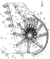
- FIG. 1a shows a folder 100 with a transport system according to an embodiment of the present invention.
- the transport system comprises a delay unit 6 and a conveyor 14 with deflection grippers.
- the folder 100 comprises a set of high-speed belts 1 which are guided by a plurality of belt rollers 3.
- the high-speed belts 1 transport the folded copies in a transport direction 100.
- the folded copies emerge from the high-speed belts 1 on a stationary guide 2.
- the stationary guide 2 has a curved surface, whereupon the folded copies 5 are guided along the outer circumference of the delay unit 6.
- the delay unit 6 receives the folded copies 5 moved along the stationary guide 2.
- Brush guides 4 are provided under the delay unit 6 to prevent the folded copies 5 from bending when they are transported through the delay unit to the deflection / conveying device 14.
- the delay unit 6 comprises a plurality of gripper heads 7 which are attached to the respective ends of rotating arms 30.
- Each gripper head 7 has a finger-shaped element 8 which can be rotated about an axis of rotation 9.
- An actuating rod 10 is connected to the axis of rotation 9 and moves the gripper head 7 about the axis of rotation 9.
- the actuating rod 10 is also coupled to a lever connection 13 having an eccentric roller 11. When the gripper head 7 moves about a central axis 40 of the delay unit 6, the eccentric rollers 11 contact an eccentrically arranged control unit 12.
- the delay unit 6 shown in FIG. 1a is disclosed in detail in the pending patent application DE 44 17 178 A1.
- the folded copies 5 are conveyed individually and not in an overlapped arrangement when they are in the delay unit 6 occur, and as a result of the delay, they are released in an overlapped, scale-like arrangement.
- the deflection / conveyor device 14, which is in contact with the delay device 6, comprises rotatable gripping elements 17 mounted on a conveyor track 15.
- the conveyor track 15 runs counterclockwise around the delay unit 6.
- the rotatable gripping elements 17 have a respective axis of rotation 18 and are further arranged along the conveyor track 15 so that there is a first regular distance 16 between them.
- the conveyor track 15 moves about the central axis 40 of the deceleration unit 6, the conveyor track 15 is largely parallel to the path which the gripper heads 7 follow along the first transfer area 500 determined by the arc length 50. This enables the folded copies 5 to be gripped by the rotatable gripping elements 17.
- the finger-shaped elements 8 of the gripper heads 7 are actuated by the controller 12, the delayed fold copies 5 being released by the delay unit 6 before they emerge from the sheet length 50.
- the rotatable gripping elements 17 grip the back of the folded copy 5 as it moves through the arc length 50. As shown in Fig. 1b, the gripper element 17 grips the back 51 of the folded copy 5, while the gripper head 7 still holds the right edge 52 of the folded copy 5.
- the folded copy is thus transferred from the gripper 7 of the delay unit 6 to the rotatable gripping elements 17 of the deflection mechanism and is continuously controlled in the process.
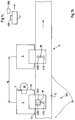
- FIG. 2a shows a top view of the deflection / conveying device 14 and a transport device 22.
- the folded copies 5 move into a second stationary guide 19 after they have been gripped by their grippers 17 on their back.
- the folded copies 5 are conveyed in a scale-like arrangement when they leave the delay unit 6.
- the folded copies 5 are gripped by the rotatable grippers 17, which have a first regular spacing 16.
- the back 51 and a rear edge 21 of the folded copies 5 are essentially parallel to one another.
- the deflection / conveying device 14 moves the folded copies 5 along the conveyor track 15.
- the second stationary guide 19 is arranged under the conveyor track 15 and supports the folded copies 5 during their transport along the conveyor track 15.
- the folded copies 5 by turning the rotatable gripping elements 17 about 90 ° around the axis 18 while moving over the second fixed guide 19. It is thus achieved that the folded copies 5 are moved backwards; d. H. that the folded copy spine 51 is deflected so that it - seen in the direction of transport - becomes the folded copy leading edge.
- the width of the second stationary guide 19 increases, namely at the position along the conveyor path 15 where rotation takes place. In this way, the second guide 19 supports the folded copies 5 during the turning process, thereby preventing damage to the folded copies.
- a transport device 22 is coupled to the deflection / conveying device 14, which comprises transport grippers 25 and a transport track 27.
- the transport grippers 25 are arranged at a second regular distance 23, which is smaller than the first regular distance 16 of the deflection grippers 17 of the conveyor device 14.
- the transport grippers 25 are mounted on the transport track 27 and follow them, which moves at a speed which is lower than the speed of the deflection conveyor track 15.
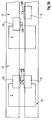
- FIG 3a shows an enlarged side view of the second transfer area, which is located between the deflection / conveying device 14 and the transport device 22.
- the deflection / conveyor device 14 extends in a curve from below the transport device 22 upwards and has a multiplicity of rotating gripping elements 17 - as described above in connection with FIGS. 1 and 2 - and each of the gripping elements 17 grips a folded copy 5 in its back-ahead position.
- the transport device 22 (which can, for example, be a conventional conveying device for individual copies) extends in a curve from top to bottom, and the deflection / conveying device 14 runs in a second transfer area 24 with a length 26 largely parallel to the transport device 22.
- the rotatable gripping elements 17 Due to the larger first regular distance 16 between the rotatable gripping elements 17 of the deflection / conveying device 14 and the higher relative speed of the deflection conveyor track 15, the rotatable gripping elements 17 overtake the transport grippers 25.
- the rotatable gripper element 17 When the rotatable gripper element 17 has moved the gripped specimen 5 completely into the slower moving transport gripper 25 of the transport device 22, the rotatable gripper element 17 releases the specimen 5 and thus its control. Shortly before or simultaneously with this release by the rotatable gripper element 17, the transport gripper 25 closes around the specimen 5 and takes over its control. Due to their higher speed, the rotatable gripping elements 17 move away from the specimens, swing upwards, follow their conveyor path 15 and complete their movement circle back to the delay unit 6.
- the transport device 22 then conveys the folded copies 5 in a shingled arrangement with a second regular spacing 23 and transmits them to further processing and production facilities or to various copy release stations.
- FIG. 4 shows an overall view of the transport system according to the present invention with the delay unit 6, the deflection / conveying device 14 and the transport device 22.
- the delay unit 6 slows down the folded copies 5, so that an arrangement lined up in a row results in an overlapping, scale-like arrangement .
- the deflecting / conveying device 14 grips the copies in a first transfer area 500 and conveys them in the scale-like arrangement at a first regular distance 16 to a second transfer area 24 with the length 26.
- the folded copies 5 are transferred to the transport device 22 which move at a lower speed than the deflection / conveying device 14, the folded copies 5 being arranged at a second regular distance 23 which is smaller than the first regular distance 16 in the deflecting / conveying device 14.
- the fold copies are controlled during the entire deflection process.
- the change of the folded copies 5 to the transport device 22 takes place via different conveying distances 16, 23. Since the release of the folded copies 5 by the deflection / conveying device 14 is only activated after the copies have been gripped by the grippers 25 of the further transport device 22, the copies are controlled 5 also maintained during their speed change.
- a first release member 300 is attached along the path of the deflection conveyor 15, within the arc length 50 of the first transfer area 500.
- Each rotatable gripper 17 comprises a first actuator 400 and a second actuator 410. If if the gripper 17 moves past the first release member 300, the latter contacts the first actuation member 400, and the latter causes the gripper 17 to take the folder 5.
- the first triggering element 300 could be designed as a rounded block and fixedly attached along the path of the deflection conveyor track 15, and the actuating element 400 could be designed as a spring-loaded projection.
- the gripping movement of the gripper 17 can, for. B.
- the grippers 7 stand out from the delay unit 6 and thus transfer control of the folded copies to the deflection / conveying device 14, the folded copies 5 being gripped by the grippers 17 on their back 51.
- the folded copies 5, which are gripped by the rotatable grippers 17, move along the deflection / conveyor track 15 to the second stationary guide 19.
- a second trigger element 310 is along the path of the deflection / conveyor track 15 attached stationary.
- the gripper 17 moves past the second release member 310, it contacts the second actuator 410 and the latter causes the gripper 17 to rotate 90 ° counterclockwise, as shown in Fig. 2b.
- the second triggering element 310 could be designed as a rounded block and fixedly attached along the path of the deflection / conveyor track 15, and the second actuating element 410 could be designed as a spring-loaded projection.
- the rotary movement of the gripper 17 about the axis 18 (which is shown as a triangle to distinguish it from the actuators 400, 410) can e.g. B. controlled by a spring, a pneumatic cylinder or other suitable device triggered by the second actuator 410.
- the folded copies 5 are gripped by grippers 25 of a transport device 27 when they have reached the transfer area 24.
- a gripper 17 overtakes a gripper 25 within the length 26 of the second transfer area 24 at the point , where a gripper 17 and a gripper 25 are parallel to one another, the grips Gripper 25 the folded copy 5. A moment later, but at least within the transfer area 26, the gripper 17 releases the folded copy 5.
- a third actuator 420 is attached to the rotatable gripper 17 and a fourth actuator 430 to the gripper 25.
- the gripper 25 grips the folder 5.
- the gripper 17 provides the folder 5 free. Since the deflection / conveyor device 14 now moves faster than the transport device 27, the gripper 17 withdraws from the folded copy and moves out of the path of the folded copy 5 after leaving the second transfer area 24. Thus, the regular distance between the overlapped folds 5 has decreased while they were continuously controlled.
Landscapes
- Engineering & Computer Science (AREA)
- Mechanical Engineering (AREA)
- Feeding Of Articles By Means Other Than Belts Or Rollers (AREA)
- Discharge By Other Means (AREA)
- Separation, Sorting, Adjustment, Or Bending Of Sheets To Be Conveyed (AREA)
- Packaging For Recording Disks (AREA)
- Folding Of Thin Sheet-Like Materials, Special Discharging Devices, And Others (AREA)
- Vending Machines For Individual Products (AREA)
Applications Claiming Priority (2)
| Application Number | Priority Date | Filing Date | Title |
|---|---|---|---|
| US50486795A | 1995-07-20 | 1995-07-20 | |
| US504867 | 1995-07-20 |
Publications (3)
| Publication Number | Publication Date |
|---|---|
| EP0754642A2 true EP0754642A2 (fr) | 1997-01-22 |
| EP0754642A3 EP0754642A3 (fr) | 1997-08-27 |
| EP0754642B1 EP0754642B1 (fr) | 2000-10-18 |
Family
ID=24008060
Family Applications (1)
| Application Number | Title | Priority Date | Filing Date |
|---|---|---|---|
| EP96108055A Expired - Lifetime EP0754642B1 (fr) | 1995-07-20 | 1996-05-21 | Méthode et dispositif de sortie de produits en forme de feuille |
Country Status (5)
| Country | Link |
|---|---|
| US (1) | US5727783A (fr) |
| EP (1) | EP0754642B1 (fr) |
| JP (1) | JPH0940261A (fr) |
| AT (1) | ATE197033T1 (fr) |
| DE (2) | DE59606007D1 (fr) |
Cited By (2)
| Publication number | Priority date | Publication date | Assignee | Title |
|---|---|---|---|---|
| EP0990535A1 (fr) * | 1998-09-28 | 2000-04-05 | Grapha-Holding Ag | Méhode pour fabriquer des produits d'imprimerie par insertion d'au moins un produit constituant dans un produit principal et dispositif pour mettre en oeuvre la méthode |
| EP1227052A1 (fr) * | 2001-01-24 | 2002-07-31 | Ferag AG | Procédé et dispositif pour changer la position de saisie des objets plats, convoyés par des pinces |
Families Citing this family (13)
| Publication number | Priority date | Publication date | Assignee | Title |
|---|---|---|---|---|
| US5957449A (en) * | 1995-04-11 | 1999-09-28 | Grapha-Holding Ag | Process and device for conveying a stream of print shop products |
| US5992610A (en) * | 1997-08-15 | 1999-11-30 | Heidelberger Druckmashinen Ag | Method and device for producing a rotated stream with a corner gripper |
| US6213459B1 (en) * | 1998-07-10 | 2001-04-10 | Heidelberger Druckmaschinen Ag | Signature gripper and delivery device |
| DE19916668B4 (de) * | 1999-04-14 | 2010-06-24 | Michael Hörauf Maschinenfabrik GmbH & Co. KG | Vorrichtung zum Transportieren von flach liegenden Zuschnitten |
| US6910690B1 (en) | 1999-07-06 | 2005-06-28 | Goss International Americas, Inc. | Positive control lower folder |
| US6357741B1 (en) | 2000-01-20 | 2002-03-19 | Heidelberger Druckmaschinen Ag | Velocity adjustable grippers on sliding carriage |
| CA2365149C (fr) * | 2000-12-27 | 2010-10-05 | Ferag Ag | Methode et dispositif pour le ramassage d'articles plats |
| JP3793948B2 (ja) * | 2003-08-25 | 2006-07-05 | 株式会社東京機械製作所 | 掴み機構付き印刷物搬送装置 |
| US8042795B2 (en) * | 2008-09-05 | 2011-10-25 | Kern International, Inc. | Transporting apparatus for discrete sheets into envelopes and related methods |
| CH701204B1 (de) * | 2009-06-02 | 2013-05-31 | Ferag Ag | Vorrichtung und Verfahren zum Fördern und gleichzeitigen Stabilisieren von flexiblen, flächigen Gegenständen. |
| CN102774685B (zh) * | 2012-08-08 | 2015-09-09 | 江苏紫荆花纺织科技股份有限公司 | 一种全自动的切膜装置 |
| CH706917A1 (de) * | 2012-09-05 | 2014-03-14 | Ferag Ag | Fördereinrichtung enthaltend einen Zuförderer, einen Wegförderer sowie einen Übergabeförderer zum Übergeben von Produkteinheiten vom Zuförderer zum Wegförderer. |
| EP3044363B1 (fr) * | 2013-09-09 | 2019-11-13 | Hangzhou Hongying Digital Technology Co., Ltd | Procédé d'imagerie numérique pour matériau de revêtement de sol |
Family Cites Families (14)
| Publication number | Priority date | Publication date | Assignee | Title |
|---|---|---|---|---|
| US3236162A (en) * | 1964-02-07 | 1966-02-22 | Ferag Fehr & Reist A G | Delivery apparatus for the products of a rotary press |
| CH468923A (de) * | 1967-07-21 | 1969-02-28 | Ferag Ag | Transporteinrichtung für in einer Schuppenformation anfallende flächenhafte Gebilde |
| US3459421A (en) * | 1967-08-09 | 1969-08-05 | John C Motter Printing Press C | Folder delivery apparatus |
| CH546197A (de) * | 1971-09-14 | 1974-02-28 | Fehr & Reist Ag | Wendefoerderer fuer flaechengebilde, insbesondere druckprodukte. |
| SE413007B (sv) * | 1977-04-12 | 1980-03-31 | Wifag Maschf | Anordning for att bilda en strom av overlappade falsade tryckprodukter |
| SE8000613L (sv) * | 1980-01-25 | 1981-07-26 | Wifag Maschf | Automatiskt verkande gripare for kedjeutleggare till tryckmaskiner |
| US4565363A (en) * | 1984-05-09 | 1986-01-21 | Custom-Bilt Machinery, Inc. | Apparatus for accurately spacing a sequence of shingled paper sheet products on a conveyor |
| EP0242702B1 (fr) * | 1986-04-18 | 1989-09-20 | Ferag AG | Procédé et dispositif pour tourner des objets plats |
| EP0265735B1 (fr) * | 1986-10-22 | 1991-01-16 | Ferag AG | Procédure et dispositif pour enlever les produits imprimés et pliés des machines d'imprimerie |
| DE3862535D1 (de) * | 1987-07-21 | 1991-05-29 | Ferag Ag | Verfahren und vorrichtung zum trennen von in schuppenformation anfallenden erzeugnissen, insbesondere druckprodukten. |
| US5007624A (en) * | 1989-05-25 | 1991-04-16 | Am International Incorporated | Sheet material handling apparatus and method |
| DE59306763D1 (de) * | 1992-04-27 | 1997-07-24 | Ferag Ag | Aktive Schnittstelle für einen Schuppenstrom von Druckprodukten |
| US5261520A (en) * | 1992-11-04 | 1993-11-16 | Am International, Inc. | Custodial book transfer system |
| US5452886A (en) * | 1993-08-09 | 1995-09-26 | Heidelberger Druckmaschinen Ag | Device for slowing down signatures in a folding machine |
-
1996
- 1996-05-21 EP EP96108055A patent/EP0754642B1/fr not_active Expired - Lifetime
- 1996-05-21 AT AT96108055T patent/ATE197033T1/de not_active IP Right Cessation
- 1996-05-21 DE DE59606007T patent/DE59606007D1/de not_active Expired - Lifetime
- 1996-05-28 DE DE19621332A patent/DE19621332A1/de not_active Withdrawn
- 1996-07-19 JP JP8191074A patent/JPH0940261A/ja active Pending
-
1997
- 1997-04-03 US US08/827,876 patent/US5727783A/en not_active Expired - Lifetime
Cited By (5)
| Publication number | Priority date | Publication date | Assignee | Title |
|---|---|---|---|---|
| EP0990535A1 (fr) * | 1998-09-28 | 2000-04-05 | Grapha-Holding Ag | Méhode pour fabriquer des produits d'imprimerie par insertion d'au moins un produit constituant dans un produit principal et dispositif pour mettre en oeuvre la méthode |
| US6254088B1 (en) | 1998-09-28 | 2001-07-03 | Grapha-Holding Ag | Method of manufacturing printed products by insetting at least one subproduct into a main product and apparatus for carrying out the method |
| EP1227052A1 (fr) * | 2001-01-24 | 2002-07-31 | Ferag AG | Procédé et dispositif pour changer la position de saisie des objets plats, convoyés par des pinces |
| US6588745B2 (en) | 2001-01-24 | 2003-07-08 | Ferag Ag | Method and device for changing the hold of flat articles being conveyed held by grippers |
| AU782812B2 (en) * | 2001-01-24 | 2005-09-01 | Ferag Ag | Method and device for changing the hold of flat articles being conveyed held by grippers |
Also Published As
| Publication number | Publication date |
|---|---|
| US5727783A (en) | 1998-03-17 |
| DE19621332A1 (de) | 1997-01-23 |
| EP0754642B1 (fr) | 2000-10-18 |
| JPH0940261A (ja) | 1997-02-10 |
| DE59606007D1 (de) | 2000-11-23 |
| EP0754642A3 (fr) | 1997-08-27 |
| ATE197033T1 (de) | 2000-11-15 |
Similar Documents
| Publication | Publication Date | Title |
|---|---|---|
| EP0911291B1 (fr) | Dispositif de pliage dans une machine plieuse à grande vitesse | |
| EP0638503B1 (fr) | Dispositif pour décélérer des exemplaires dans un appareil de pliage | |
| DE2518373C2 (de) | Einrichtung zum Vergleichmässigen der gegenseitigen Abstände von in einem Schuppenstrom aufeinanderfolgenden Druckprodukten | |
| EP0415077B1 (fr) | Appareil de pliage | |
| EP0754642B1 (fr) | Méthode et dispositif de sortie de produits en forme de feuille | |
| CH667621A5 (de) | Sammelhefter. | |
| EP0755783A2 (fr) | Machine d'impression avec guidage rectiligne d'un substrat et dispositifs de retournement | |
| CH623288A5 (fr) | ||
| CH623286A5 (fr) | ||
| EP0498068A1 (fr) | Plieuse, dans laquelle le transport d'exemplaires pliés est realisé en passant par des moyens de transport, des galets partiels et des cordons | |
| EP0323557B1 (fr) | Dispositif de transport de produits plats, en particulier de produits imprimés | |
| CH649972A5 (de) | Vorrichtung zum uebereinanderlegen von einzelnen flaechigen erzeugnissen, insbesondere druckprodukten. | |
| DE3023533C2 (de) | Vorrichtung zum Ablegen von Bogen in einem Stapel | |
| EP0897890B1 (fr) | Procédé et dispositif pour produire un courant de produits tournés avec une pince de préhension de coin | |
| DE69702107T2 (de) | Entnahme von Druckbogen-Proben | |
| DE19621331B4 (de) | Vorrichtung zur Aufteilung eines Produktstroms | |
| EP0407763A1 (fr) | Dispositif pour enlever des produits imprimés d'une roue à aubes entraînée en rotation faisant partie d'une machine d'impression | |
| EP1193201B1 (fr) | Méthode et dispositif pour former une formation imbriquée double de produits imprimés | |
| DE4439092C2 (de) | Vorrichtung zum Zuführen von Bogen | |
| EP0307889A2 (fr) | Dispositif pour émettre des imprimés à partir des roues à aubes d'une plieuse | |
| DE2832660C3 (de) | Vorrichtung zum gruppenweisen Abteilen von geschuppt übereinanderliegend geförderten Werkstücken | |
| DE3914178C2 (fr) | ||
| EP0300170B1 (fr) | Procédé et dispositif de séparation de produits se chevauchant, en particulier de produits imprimés | |
| EP0896942B1 (fr) | Dispositif pour diviser des courants d'exemplaires derrière un appareil de pliage | |
| EP0518064B1 (fr) | Procédé et appareil pour la manutention de produits imprimés |
Legal Events
| Date | Code | Title | Description |
|---|---|---|---|
| PUAI | Public reference made under article 153(3) epc to a published international application that has entered the european phase |
Free format text: ORIGINAL CODE: 0009012 |
|
| 17P | Request for examination filed |
Effective date: 19960521 |
|
| AK | Designated contracting states |
Kind code of ref document: A2 Designated state(s): AT CH DE FR GB LI |
|
| PUAL | Search report despatched |
Free format text: ORIGINAL CODE: 0009013 |
|
| AK | Designated contracting states |
Kind code of ref document: A3 Designated state(s): AT CH DE FR GB LI |
|
| 17Q | First examination report despatched |
Effective date: 19971125 |
|
| RTI1 | Title (correction) |
Free format text: METHOD AND DEVICE FOR DELIVERING SHEET-LIKE PRODUCTS |
|
| GRAG | Despatch of communication of intention to grant |
Free format text: ORIGINAL CODE: EPIDOS AGRA |
|
| GRAG | Despatch of communication of intention to grant |
Free format text: ORIGINAL CODE: EPIDOS AGRA |
|
| GRAH | Despatch of communication of intention to grant a patent |
Free format text: ORIGINAL CODE: EPIDOS IGRA |
|
| GRAH | Despatch of communication of intention to grant a patent |
Free format text: ORIGINAL CODE: EPIDOS IGRA |
|
| GRAA | (expected) grant |
Free format text: ORIGINAL CODE: 0009210 |
|
| AK | Designated contracting states |
Kind code of ref document: B1 Designated state(s): AT CH DE FR GB LI |
|
| REF | Corresponds to: |
Ref document number: 197033 Country of ref document: AT Date of ref document: 20001115 Kind code of ref document: T |
|
| REG | Reference to a national code |
Ref country code: CH Ref legal event code: EP |
|
| REF | Corresponds to: |
Ref document number: 59606007 Country of ref document: DE Date of ref document: 20001123 |
|
| GBT | Gb: translation of ep patent filed (gb section 77(6)(a)/1977) |
Effective date: 20001115 |
|
| ET | Fr: translation filed | ||
| PLBE | No opposition filed within time limit |
Free format text: ORIGINAL CODE: 0009261 |
|
| STAA | Information on the status of an ep patent application or granted ep patent |
Free format text: STATUS: NO OPPOSITION FILED WITHIN TIME LIMIT |
|
| 26N | No opposition filed | ||
| REG | Reference to a national code |
Ref country code: GB Ref legal event code: IF02 |
|
| PGFP | Annual fee paid to national office [announced via postgrant information from national office to epo] |
Ref country code: GB Payment date: 20030422 Year of fee payment: 8 |
|
| PGFP | Annual fee paid to national office [announced via postgrant information from national office to epo] |
Ref country code: FR Payment date: 20030522 Year of fee payment: 8 |
|
| PGFP | Annual fee paid to national office [announced via postgrant information from national office to epo] |
Ref country code: AT Payment date: 20030523 Year of fee payment: 8 |
|
| PG25 | Lapsed in a contracting state [announced via postgrant information from national office to epo] |
Ref country code: GB Free format text: LAPSE BECAUSE OF NON-PAYMENT OF DUE FEES Effective date: 20040521 Ref country code: AT Free format text: LAPSE BECAUSE OF NON-PAYMENT OF DUE FEES Effective date: 20040521 |
|
| GBPC | Gb: european patent ceased through non-payment of renewal fee |
Effective date: 20040521 |
|
| PG25 | Lapsed in a contracting state [announced via postgrant information from national office to epo] |
Ref country code: FR Free format text: LAPSE BECAUSE OF NON-PAYMENT OF DUE FEES Effective date: 20050131 |
|
| REG | Reference to a national code |
Ref country code: FR Ref legal event code: ST |
|
| PGFP | Annual fee paid to national office [announced via postgrant information from national office to epo] |
Ref country code: CH Payment date: 20110525 Year of fee payment: 16 |
|
| PGFP | Annual fee paid to national office [announced via postgrant information from national office to epo] |
Ref country code: DE Payment date: 20110527 Year of fee payment: 16 |
|
| REG | Reference to a national code |
Ref country code: CH Ref legal event code: PL |
|
| PG25 | Lapsed in a contracting state [announced via postgrant information from national office to epo] |
Ref country code: CH Free format text: LAPSE BECAUSE OF NON-PAYMENT OF DUE FEES Effective date: 20120531 Ref country code: LI Free format text: LAPSE BECAUSE OF NON-PAYMENT OF DUE FEES Effective date: 20120531 |
|
| REG | Reference to a national code |
Ref country code: DE Ref legal event code: R119 Ref document number: 59606007 Country of ref document: DE Effective date: 20121201 |
|
| PG25 | Lapsed in a contracting state [announced via postgrant information from national office to epo] |
Ref country code: DE Free format text: LAPSE BECAUSE OF NON-PAYMENT OF DUE FEES Effective date: 20121201 |