EP0754644B1 - Cylindre de coupe avec barre de coupe réglable - Google Patents
Cylindre de coupe avec barre de coupe réglable Download PDFInfo
- Publication number
- EP0754644B1 EP0754644B1 EP96810447A EP96810447A EP0754644B1 EP 0754644 B1 EP0754644 B1 EP 0754644B1 EP 96810447 A EP96810447 A EP 96810447A EP 96810447 A EP96810447 A EP 96810447A EP 0754644 B1 EP0754644 B1 EP 0754644B1
- Authority
- EP
- European Patent Office
- Prior art keywords
- cutter bar
- cutting cylinder
- adjusting means
- pressure
- cylinder according
- Prior art date
- Legal status (The legal status is an assumption and is not a legal conclusion. Google has not performed a legal analysis and makes no representation as to the accuracy of the status listed.)
- Expired - Lifetime
Links
Images


Classifications
-
- B—PERFORMING OPERATIONS; TRANSPORTING
- B65—CONVEYING; PACKING; STORING; HANDLING THIN OR FILAMENTARY MATERIAL
- B65H—HANDLING THIN OR FILAMENTARY MATERIAL, e.g. SHEETS, WEBS, CABLES
- B65H45/00—Folding thin material
- B65H45/12—Folding articles or webs with application of pressure to define or form crease lines
- B65H45/16—Rotary folders
- B65H45/162—Rotary folders with folding jaw cylinders
- B65H45/168—Rotary folders with folding jaw cylinders having changeable mode of operation
-
- B—PERFORMING OPERATIONS; TRANSPORTING
- B26—HAND CUTTING TOOLS; CUTTING; SEVERING
- B26D—CUTTING; DETAILS COMMON TO MACHINES FOR PERFORATING, PUNCHING, CUTTING-OUT, STAMPING-OUT OR SEVERING
- B26D7/00—Details of apparatus for cutting, cutting-out, stamping-out, punching, perforating, or severing by means other than cutting
- B26D7/26—Means for mounting or adjusting the cutting member; Means for adjusting the stroke of the cutting member
- B26D7/2628—Means for adjusting the position of the cutting member
-
- Y—GENERAL TAGGING OF NEW TECHNOLOGICAL DEVELOPMENTS; GENERAL TAGGING OF CROSS-SECTIONAL TECHNOLOGIES SPANNING OVER SEVERAL SECTIONS OF THE IPC; TECHNICAL SUBJECTS COVERED BY FORMER USPC CROSS-REFERENCE ART COLLECTIONS [XRACs] AND DIGESTS
- Y10—TECHNICAL SUBJECTS COVERED BY FORMER USPC
- Y10T—TECHNICAL SUBJECTS COVERED BY FORMER US CLASSIFICATION
- Y10T83/00—Cutting
- Y10T83/929—Tool or tool with support
- Y10T83/9372—Rotatable type
- Y10T83/9396—Shear type
- Y10T83/9399—Cutting edge wholly parallel to axis of rotation
-
- Y—GENERAL TAGGING OF NEW TECHNOLOGICAL DEVELOPMENTS; GENERAL TAGGING OF CROSS-SECTIONAL TECHNOLOGIES SPANNING OVER SEVERAL SECTIONS OF THE IPC; TECHNICAL SUBJECTS COVERED BY FORMER USPC CROSS-REFERENCE ART COLLECTIONS [XRACs] AND DIGESTS
- Y10—TECHNICAL SUBJECTS COVERED BY FORMER USPC
- Y10T—TECHNICAL SUBJECTS COVERED BY FORMER US CLASSIFICATION
- Y10T83/00—Cutting
- Y10T83/929—Tool or tool with support
- Y10T83/9372—Rotatable type
- Y10T83/9406—Radially adjustable tool
-
- Y—GENERAL TAGGING OF NEW TECHNOLOGICAL DEVELOPMENTS; GENERAL TAGGING OF CROSS-SECTIONAL TECHNOLOGIES SPANNING OVER SEVERAL SECTIONS OF THE IPC; TECHNICAL SUBJECTS COVERED BY FORMER USPC CROSS-REFERENCE ART COLLECTIONS [XRACs] AND DIGESTS
- Y10—TECHNICAL SUBJECTS COVERED BY FORMER USPC
- Y10T—TECHNICAL SUBJECTS COVERED BY FORMER US CLASSIFICATION
- Y10T83/00—Cutting
- Y10T83/929—Tool or tool with support
- Y10T83/9457—Joint or connection
- Y10T83/9464—For rotary tool
- Y10T83/9469—Adjustable
- Y10T83/9471—Rectilinearly
Definitions
- the present invention relates to a knife cylinder for cross cutting or perforate a material web running in a rotary machine after the Preamble of claim 1.
- the knife of the knife cylinder must be adjustable.
- the preferred, but not in principle the only area of application of the invention is this adjustability for example when switching from collective to Double production or vice versa desired.
- a knife bar by means of compressive forces that can be applied to its two long sides, in Circumferential direction on a cylinder-side traversing surface.
- pressure hoses extending along the sides, which can be mutually loaded with a pressure medium.
- a spring opposite such a pressure hose provided against the restoring force of the cutter bar through the pressure hose is movable.
- the knife cylinder is supported by several sliding blocks Pressure springs are pressed on the cutter bar, on the travel surface of the Knife cylinder pressed.
- a knife bar formed wedge-shaped at least on one of its long sides. This long side is frictionally with a complementary wedge-shaped, in the axial direction of the Knife cylinder movable bar connected by friction. The shift of the Cutter bar in the circumferential direction again takes place against return springs act against the opposite long side of the cutter bar.
- a knife bar is in the circumferential direction move the cylinder by a compressive force causing the process is applied to the cutter bar via a wedge surface.
- this wedge surface at an acute angle to a traversing surface of the knife cylinder.
- the travel area is the area on which the cutter bar is pressed and on which it can be moved. Due to the orientation of the Wedge surface, via which the pressure force acts on the cutter bar, is the on the Knife bar acting external force divided into two components, of which the first the knife bar moves while the second component does the Cutter bar against its cylinder-side support, namely the travel surface, presses.
- the additional holding means known from the prior art can thus be saved with the inventive design of the cutter bar.
- Adjustment means not only via a wedge surface, but via two complementary ones Wedge surfaces on the cutter bar.
- One of the two wedge surfaces is on the cutter bar and the other is formed on the actuating means.
- the adjustment means is preferably substantially perpendicular to the travel surface of the Knife cylinder can be moved back and forth.
- the direction of movement of the In principle, however, the adjusting means can also be tilted relative to the travel surface be.
- each at least one adjusting means according to the invention is on both long sides of the cutter bar each at least one adjusting means according to the invention.
- the knife bar is fixed by the adjusting means Move stop.
- the fixed stop is rigid with the knife cylinder can be connected, it is preferably through to the other long side of the Knife bar arranged adjusting means formed for this purpose in a corresponding Stop position is brought.
- this adjustment means moves back into his Stop position, it can be quite advantageous if this adjustment with a force on the cutter bar while moving the cutter bar presses, which is however less than that of the "active" adjusting means. It can be in its stop position continues to be opposite the pressure force of the active one Use a small elastic restoring force on the cutter bar in this position, however, fixed in such a way that it is no longer against restoring forces is movable and thereby forms the fixed stop for the cutter bar itself.
- the adjusting means is in by an elastic biasing force Pressure on the cutter bar.
- the biasing force is preferred by a spring, in particular a compression spring in the form of a spring assembly applied so that it is ensured with a high degree of certainty that the cutter bar is always clamped against its cylinder-side travel surface.
- the functional reliability is particularly high because the spring force independent of the cutter bar other systems susceptible to faults are always fixed in a stop position.
- the pressure of the adjusting means caused by the prestressing force is preferred can be reduced to the cutter bar.
- Especially an external counterforce to the prestressing force on the adjusting means is preferred applied by a printing medium. Air is advantageously used as the pressure medium or oil or a combination thereof, especially in the form of two in a row switched circuits.
- a cutter bar is made of plastic, so because of the low specific weight of plastic the acting on the cutter bar Centrifugal force due to the cylinder rotation remains as low as possible.
- This can the pre-tensioning force acting on the adjusting means, which presses against the Knife bar generated, be kept lower than with a knife bar made of steel or light metal.
- the ones that generate the preload Means, preferably spring assemblies, are thereby relieved.
- For further Relief can advantageously also be made of plastic from the adjusting means be.
- Figure 1 shows the entry of a printing web B in a folder.
- Two already folded printing part web B1 and B2 each run over a pair of draw rollers 1 and are after deflection of the printing web B1 by a register roller 2 and a subsequent deflection roller 3 merged behind this deflection roller 3.
- the merged printing web B then passes through a pair of draw rollers 4 a downstream restraint 5 before passing through a clipper 6 is performed.
- Behind the cutting device 6 is a further pair of pull rollers 7 arranged, after its passage the printing web B a collecting cylinder 8th a folder is fed.
- the looping around the collecting cylinder 8 Printing web is cross-cut by means of a knife cylinder 9.
- the cut ones Print copies are then from the collecting cylinder 8 to a jaw cylinder 10 handed over, cross-folded and then reach via a paddle wheel 11 a display.
- the print copies each have the same length, should the inner part of a printed product in the case of collective production shorter than the outer part so that when cutting the outer part there is not a short piece of the inner part Partly cut off, which leads to contamination of the folder and thus would cause malfunctions.
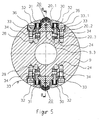
- Figure 2 shows in cross section the two-part knife cylinder 9 with two themselves diametrically opposite, movable in the circumferential direction of the cylinder 9, in Embodiment slidably, knife bar 20.
- the two Cutter bars 20 can each be in two fixed positions, in the following stop positions called, be positioned.
- the first stop position of the cutter bars 20 is in Figure 2 set. In this stop position, the knife cylinder 9 is open Double production stopped.
- the circumferential distance from the cutter bar to Knife bar or knife to knife is the same in both circumferential directions.
- the two cutter bars are in collective production in their second stop positions method. This position of the cutter bars is shown in Figure 3.
- the cutter bars 20 have both been moved towards each other, so that one length of cut of the printing web is larger and the other is smaller. It is to make sure that the short copy first on the Collection cylinder 8 is passed and the long specimen is then over it comes, so that after the second cross fold in the jaw cylinder 10 a regular long, i.e. flush, printed copy is created.
- the two cutter bars 20 of the cutter cylinder 9 according to FIG. 2 and their assigned adjustment devices are identical, so that in the following Reference is only made to one cutter bar or one adjustment device becomes.
- the cutter bar 20 essentially has a T-shaped in the exemplary embodiment Cross-sectional shape.
- a knife is centered in a receiving part 20.1 held, which points radially to an axis of rotation of the knife cylinder.
- the "crossbar" of the T forms a guide part 20.2, which is on both sides of the receiving part 20.1 stands out.
- the underside of the guide part 20.2 facing the cylinder axis of rotation forms a support surface 20.3 for the cutter bar 20.
- This support surface 20.3 slides in the circumferential direction of the knife cylinder when the knife bar is moved 9 on a corresponding counter surface 9.3 of the knife cylinder, which follows is referred to as the traversing surface.
- the adjustment of the cutter bar 20 in the circumferential direction of the cutter cylinder 9 is carried out by adjusting means 23 which on both longitudinal sides of the cutter bar 20 in Area of the side walls of a cylinder-side receiving groove for the cutter bar are arranged.
- Such an adjusting means is formed by a pressure pin 23, the perpendicular to the direction of travel V of the cutter bar 20 and perpendicular to Cylinder axis of rotation is straight.
- the pressure pin 23 is in the manner of a Piston displaceable in its guide provided in the knife cylinder 9.
- the bolt 23 on one of its end faces constantly by the force of a spring assembly 22 is biased while it is in the area of its opposite, end face with a pressure medium, in the exemplary embodiment compressed air or hydraulic oil, can be acted upon via a feed 24 or 28.
- a pressure medium in the exemplary embodiment compressed air or hydraulic oil
- the adjustment of the cutter bar 20 is effected in that two are opposite the adjustment direction V sloping planes slide on each other if that Adjustment means 23 presses against the cutter bar 20.
- the right wedge surface 25 in the illustration according to FIG. 2 and the left one Wedge surface 27, on the guide part 20.2, opposite the bearing surface 20.3, are trained.
- the adjusting means 23 each have a corresponding counter wedge surface 23.1, which are complementary to the corresponding wedge surface 25 or 27 of the Cutter bar 20 runs, i.e. the wedge surfaces 25, 27 and their counter wedge surface 23.1 have the same pitch angle ⁇ .
- the pitch angle ⁇ of the knife bar-side guide surfaces 25 and 27 is the angle that each of the Wedge surfaces 25 and 27 with the support surface 20.3 of the cutter bar 20 includes.
- the counter wedge surface 23.1 on the actuating means 23 points in the cross-sectional illustration seen the same pitch angle to the circumferential direction.
- the pitch angle ⁇ is in the preferred material pairings of the sliding surfaces about 30 °, which is preferred also represents a lower minimum value for the pitch angle so that the Self-locking problem cannot occur from the outset.
- the adjusting means 23 has the Knife bar 20 side facing a recess into which the guide part 20.2 of the cutter bar 20 protrudes.
- One of the two opposite Side walls of the recess form the wedge surface 23.1.
- the side walls of the groove, in which the cutter bar 20 is received have a corresponding recess on, so that when adjusting the cutter bar 20, the guide part 20.2 only comes into contact with the adjusting means 23.
- the adjusting means 23 occurs itself seen in the cross-sectional view of Figure 2 behind the side wall of the receiving groove otherwise a small piece back for the cutter bar 20.
- Adjustment means 23.1 equidistantly distributed over the axial length of the cutter bar 20 arranged.
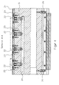
- there are 20 on each side of the cutter bar four adjustment means 23 are provided, as shown in the longitudinal sectional view A-A of the Figure 4 can be seen.
- the four adjusting means 23 arranged in alignment are via the common pressure line 24 and 28 with the pressure fluid acted upon.
- the pressure line 24 or 28 is a simple blind bore in the Knife cylinder 9 executed.
- the pressure fluid is supplied via a Rotary connection on one side of the knife cylinder 9.
- the adjusting means or adjusting pistons 23 are in simple bores directly behind the side wall of the receiving groove for the cutter bar 20 added.
- a restock for the spring assemblies 22 is used in Area of a corresponding recess on the outer circumference of the knife cylinder 9 screwed down hold-down bar 21 or 26 ( Figure 2).
- two side stops 29 are also shown, through which the cutter bar 20 (in section A-A the lower cutter bar in FIG. 2) fixed in the cylinder axis direction is.
- FIG. 33 An alternative embodiment 33 of the adjusting means is shown in FIG. While the adjusting means 23 in the exemplary embodiment according to FIGS. 4 through each a pressure pin or adjusting piston is formed, which itself with the Counter wedge surface 23.1 is provided, i.e. which acts directly on the cutter bar the part of the adjusting means according to FIG. 5 acting on the cutter bar 20 a bar 33 is formed, which extends substantially over the entire axial length of the Cutter bar 20 extends.
- This bar 33 like the adjusting means 23 according to the Figures 2-4, by at least one compression spring assembly 32 against the pressure Wedge surface of the cutter bar 20 biased. This biasing force of the spring assembly 32 acts a pressure piston 34 arranged opposite the spring assembly 32 opposite.
- FIG. 5 corresponds otherwise that of the adjusting means 23 according to Figures 2 to 4, so that on the Description of these figures is referred.
- Figure 6 seen from the axis of rotation of the knife cylinder 9 outer longitudinal edge of the strip 33 four spring assemblies 32 equidistantly over the axial Length of the bar 33 arranged distributed. Opposite each of the spring assemblies 32 is on an inner seen from the axis of rotation of the knife cylinder 9
- a piston 34 is arranged along the longitudinal edge of the strip 33.
- the pressure pistons 34 are over a common blind bore 24 can be pressurized.
- the bar 33 and the Pistons 34 can, but are not in one piece in the exemplary embodiment educated.
- the strip 33 is preferably made of a plastic material.
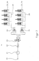
- FIGS. 7 to 9 show three alternative designs for a pressure change circuit shown.
- the Pressure lines 24 and 28 and thus to the two sides of a cutter bar 20 arranged rows of pressure pistons 23 and 34 ( Figure 2, Figure 5) with a suitable pressure medium and the adjustment of the cutter bar 20 controlled.
- the pressure change circuit according to Figure 7 is by a compressed air circuit and a Hydraulic circuit, which are separated from one another by pistons 44 and 45.
- Compressed air is supplied by a compressed air source 40 at the usual pressure of approximately 6 cash provided. It comes from the compressed air source via a line 40 to a rotary connection 41 and from there via a check valve 42 to one Four / two-way valve 43.
- One of the two outputs 43.1 and 43.2 of the valve 43 stands with an air pressure chamber of one of the two double-acting pistons 44 and 45 in connection.
- the second, opposite the air pressure chamber The pressure chamber of each of these two pistons 44 and 45 is filled with hydraulic oil.
- Oil pressure chamber of the piston 44 is connected to the pressure line 24 and the oil pressure chamber Piston 45 is connected to the pressure line 28.
- the air pressure of the air pressure source 40 is at the outlet 43.2 of the valve 43.
- the piston 45 is acted upon on one side with compressed air. over The oil pressure line 28 is thus printed on the double-acting piston 45.
- the other pistons 44 is depressurized via valve 43. this applies accordingly for the associated oil pressure line 24.
- FIG Switch position of the valve 43 shown takes the cutter bar 20 or each Cutter bar 20 in its stop position shown in Figures 2 and 5.
- the pressure conditions in the Oil pressure lines 24 and 28 reversed, i.e.
- each right adjusting means 23 and 33 pressurized so that they as Stops for the knife bar or 20 serve and this knife bar 20 the Assume stop positions shown in Figure 3.
- the one shown in Figure 7 Series connection with compressed air and two hydraulic circuits has the advantage that the rotary connection 41 as a connecting link to the rotating knife cylinder only Compressed air leads, which in the event of a leak, at least no additional Pollution problems.
- the check valve 42 prevents one Pressure drop if the compressed air source 40 fails or the rotary connection 41 leaks should.
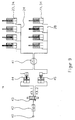
- FIG. 8 shows an alternative pressure circuit that only with hydraulic oil is operated.
- a pump 50 delivers from an oil reservoir 51 via a Line 50.1 hydraulic oil and via its pressure outlet 50.2 to the rotary connection 41 and from there via the check valve 42 to the four / two-way valve 43.
- switching position of the valve 43 is the oil pressure at the valve outlet 43.2 on, so that the pressure line 28 is printed.
- the pressure line 24 stands with the second outlet of the valve 43 in connection, which is shown in the illustration in FIG. 8 in turn is connected to the oil reservoir 51 via the rotary connection 41, so that in turn the pressure line 24 is depressurized. They turn up same pressure conditions as in the pressure circuit of Figure 7.
- the second Switching position of the valve 43 the pressure conditions are reversed.
- the use of a pure hydraulic circuit has the advantage in particular faster switching times.
- compressed air is again used provided by a compressed air source 40 and in turn via a check valve led to the four / two-way valve 43. Its two outputs 43.1 and 43.2 are again connected to the double-acting pistons 44 and 45. How in the example according to FIG. 7, one is found by the two pistons 44 and 45 End coupling of air and oil circuit instead.
- One side of the piston is compressed air and the other with hydraulic oil.
- the piston 44 oil pressure chamber stands over the rotary connection 41 with the pressure line 24 and the oil pressure chamber of the Piston 45 is also connected to the pressure line 28 via the rotary connection 41 Connection. It is again in the switching position of the valve 43 according to FIG. 9 the same pressure ratios as in the two previous cases.
- a Switching the valve 43 in turn causes the pressure conditions to be reversed. In In this variant, switching takes place outside the rotating cylinder and is therefore advantageously stationary.
Landscapes
- Life Sciences & Earth Sciences (AREA)
- Forests & Forestry (AREA)
- Engineering & Computer Science (AREA)
- Mechanical Engineering (AREA)
- Details Of Cutting Devices (AREA)
- Folding Of Thin Sheet-Like Materials, Special Discharging Devices, And Others (AREA)
Claims (13)
- Cylindre de coupe (9) pour couper ou perforer transversalement une bande de matériau passant dans une rotative, de préférence une bande imprimée dans une rotative à imprimer, comportant au moins une barre de coupe (20) dans laquelle est fixée une lame et qui peut être déplacée avec une surface d'appui (20.3) contre une surface de déplacement (9.3) réalisée sur le cylindre de coupe (9) en exerçant une pression dans la direction circonférentielle du cylindre de coupe (9) par le fait qu'un organe de réglage (23) pouvant se déplacer dans le cylindre de coupe (9) exerce une pression sur la barre de coupe (20) par l'intermédiaire d'au moins une surface en forme de clavette (23.1; 33.1; 25; 27),
caractérisé en ce quea) cette surface en forme de clavette (25, 27), au nombre d'au moins une, est inclinée suivant un angle aigu (α) par rapport à la surface de déplacement (9.3), et queb) l'angle d'inclinaison (α) est choisi en fonction des paires de matériau de la barre de coupe (20) et du cylindre de coupe (9) et de la barre de coupe (20) et des moyens de réglage (23 ; 33) de manière à ce qu'il ne soit pas irréversible. - Cylindre de coupe selon la revendication 1, caractérisé en ce qu'il est prévu une première surface en forme de clavette (25 ; 27) sur la barre de coupe (20) et une surface en forme de clavette conjuguée (23.1 ; 33.1) sur le moyen de réglage (23 ; 33).
- Cylindre de coupe selon la revendication 1 ou 2, caractérisé en ce que le moyen de réglage (23 ; 33) peut effectuer un mouvement rectiligne de vaet-vient sensiblement perpendiculairement à la surface de déplacement (9.3).
- Cylindre de coupe selon l'une des revendications précédentes, caractérisé en ce qu'un premier moyen de réglage (23 ; 33 ; 36) agissant par l'intermédiaire d'au moins une surface en forme de clavette (23.1 ; 33.1 ; 25 ; 35) est disposé sur un des côtés longitudinaux de la barre de coupe (20) et qu'un deuxième moyen de réglage (23 ; 33) agissant par l'intermédiaire d'au moins une autre surface en forme de clavette (23.1 ; 33.1 ; 27) est disposé sur le côté longitudinal opposé.
- Cylindre de coupe selon l'une des revendications précédentes, caractérisé en ce que la barre de coupe (20) est déplacée, sous la pression du premier ou du deuxième moyen de réglage (33), contre l'autre moyen de réglage (33) qui forme une butée fixe pour la barre de coupe (20).
- Cylindre de coupe selon la revendication 4, caractérisé en ce que la barre de coupe (20) est déplacée, sous la pression du premier ou du deuxième moyen de réglage (33), contre la surface en forme de clavette (27 ; 25) du cylindre de coupe (9) qui forme une butée fixe pour la barre de coupe (20).
- Cylindre de coupe selon l'une des revendications précédentes, caractérisé en ce que le moyen de réglage (23; 33) est amené en appui contre la barre de coupe (20) par une force de précontrainte élastique, de préférence par au moins un ressort (22 ; 32).
- Cylindre de coupe selon l'une des revendications précédentes, caractérisé en ce qu'uneppresion exercée par le moyen de réglage (23 ; 33) sur la barre de coupe (20) est réduite en sollicitant le moyen de réglage (23 ; 33) par une force antagoniste qui peut être appliquée de préférence au moyen d'un fluide sous pression.
- Cylindre de coupe selon l'une des revendications précédentes, caractérisé en ce qu'un premier et un deuxième moyens de réglage (23 ; 33), qui sont respectivement disposés sur un côté longitudinal de la barre de coupe (20), peuvent être soumis alternativement à une pression plus importante et à une pression plus faible, l'un des deux moyens de réglage (23 ; 33) étant de préférence exempt de pression.
- Cylindre de coupe selon l'une des revendications précédentes, caractérisé en ce que le moyen de réglage est formé par au moins un axe (23) réalisé à la manière d'un piston sur la première surface terminale duquel agit un ressort de pression (22) renforçant une pression de l'axe (23) sur la barre de coupe (20) et qui, dans la région de sa deuxième surface terminale, est sollicité par une force antagoniste pouvant être appliquée par un fluide sous pression.
- Cylindre de coupe selon l'une des revendications précédentes, caractérisé en ce que plusieurs axes (23) sont répartis sur les côtés longitudinaux de la barre de coupe (20).
- Cylindre de coupe selon l'une des revendications 1 à 9, caractérisé en ce que le moyen de réglage est formé par une nervure (33) qui s'étend sur le côté longitudinal de la barre de coupe (20), sur un premier côté longitudinal de laquelle agit au moins un ressort de pression (32) produisant une pression de la nervure (33) sur la barre de coupe (20) et qui, sur un deuxième côté longitudinal situé à l'opposé du premier côté longitudinal, est sollicitée par une force antagoniste pouvant être appliquée par un fluide sous pression.
- Cylindre de coupe selon l'une des revendications précédentes, caractérisé en ce que la barre de coupe (20) présente une section en forme de T avec un élément de réception (20.1) pour une lame qui est orienté dans la direction radiale par rapport à un axe de rotation du cylindre de coupe (9) et avec un élément de guidage (20.2) qui fait saillie de part et d'autre de l'élément de réception (20.1) et sur lequel sont réalisées la surface d'appui (20.3) et, en vis-à-vis de la surface d'appui (20.3), la surface en forme de clavette (25; 27), au nombre d'au moins une, de préférence au moins une surface en forme de clavette (25, 27) sur chacun des deux côtés de l'élément de réception (20.1).
Applications Claiming Priority (2)
| Application Number | Priority Date | Filing Date | Title |
|---|---|---|---|
| DE19526507A DE19526507C2 (de) | 1995-07-20 | 1995-07-20 | Messerzylinder mit verstellbarem Messerbalken |
| DE19526507 | 1995-07-20 |
Publications (2)
| Publication Number | Publication Date |
|---|---|
| EP0754644A1 EP0754644A1 (fr) | 1997-01-22 |
| EP0754644B1 true EP0754644B1 (fr) | 1999-03-10 |
Family
ID=7767342
Family Applications (1)
| Application Number | Title | Priority Date | Filing Date |
|---|---|---|---|
| EP96810447A Expired - Lifetime EP0754644B1 (fr) | 1995-07-20 | 1996-07-11 | Cylindre de coupe avec barre de coupe réglable |
Country Status (3)
| Country | Link |
|---|---|
| US (1) | US5771770A (fr) |
| EP (1) | EP0754644B1 (fr) |
| DE (2) | DE19526507C2 (fr) |
Cited By (1)
| Publication number | Priority date | Publication date | Assignee | Title |
|---|---|---|---|---|
| DE102021101992A1 (de) | 2021-01-28 | 2022-07-28 | Manroland Goss Web Systems Gmbh | Klemmleiste für Messerbalken |
Families Citing this family (12)
| Publication number | Priority date | Publication date | Assignee | Title |
|---|---|---|---|---|
| ES2155334B1 (es) * | 1998-06-01 | 2002-02-01 | Com Ind Maquinaria Carton Ondu | Sistema para la sujecion de troqueles rotativos en maquinas troqueladoras de material laminar. |
| US6539829B1 (en) * | 1999-06-03 | 2003-04-01 | C. G. Bretting Manufacturing Company, Inc. | Rotary valve assembly and method |
| US6418828B1 (en) * | 1999-06-24 | 2002-07-16 | The Procter & Gamble Company | Force-adjustable rotary apparatus for working webs or sheets of material |
| US6296601B1 (en) * | 1999-07-13 | 2001-10-02 | C.G. Bretting Manufacturing Company, Inc. | Vacuum assisted roll apparatus and method |
| DE102006005121A1 (de) * | 2006-02-04 | 2007-08-09 | Peter Mayr | Falzwerk einer Druckmaschine mit mindestens einer Steuervorrichtung für Funktionseinheiten |
| DE102007058816A1 (de) * | 2007-12-05 | 2009-06-10 | Krones Ag | Schneidwerkzeug zum Schneiden von Etiketten |
| US8986253B2 (en) | 2008-01-25 | 2015-03-24 | Tandem Diabetes Care, Inc. | Two chamber pumps and related methods |
| US8408421B2 (en) | 2008-09-16 | 2013-04-02 | Tandem Diabetes Care, Inc. | Flow regulating stopcocks and related methods |
| AU2009293019A1 (en) | 2008-09-19 | 2010-03-25 | Tandem Diabetes Care Inc. | Solute concentration measurement device and related methods |
| EP3284494A1 (fr) | 2009-07-30 | 2018-02-21 | Tandem Diabetes Care, Inc. | Système de pompe à perfusion portable |
| US9180242B2 (en) | 2012-05-17 | 2015-11-10 | Tandem Diabetes Care, Inc. | Methods and devices for multiple fluid transfer |
| US9173998B2 (en) | 2013-03-14 | 2015-11-03 | Tandem Diabetes Care, Inc. | System and method for detecting occlusions in an infusion pump |
Family Cites Families (26)
| Publication number | Priority date | Publication date | Assignee | Title |
|---|---|---|---|---|
| US1685532A (en) * | 1927-10-01 | 1928-09-25 | Duplex Printing Press Co | Knife bar for paper cutting and folding machines |
| US1937519A (en) * | 1932-01-26 | 1933-12-05 | Hoe & Co R | Cutting apparatus |
| US1963734A (en) * | 1933-07-12 | 1934-06-19 | Goss Printing Press Co Ltd | Cutting and collecting mechanism for printing presses |
| US2095631A (en) * | 1936-07-06 | 1937-10-12 | United States Gypsum Co | Cutting device |
| US3128663A (en) * | 1961-02-06 | 1964-04-14 | Norman E Dovey | Knife support |
| DE1241248B (de) * | 1964-06-26 | 1967-05-24 | Ibm | Vorrichtung zum Befestigen einer Schneidklinge in einer Laengsnut eines umlaufenden Schneidzylinders |
| US3251256A (en) * | 1964-06-26 | 1966-05-17 | Ibm | Fluid actuated toolholder |
| US3288007A (en) * | 1964-10-05 | 1966-11-29 | Eda Masumi | Paper holding apparatus for cutting cylinder in a rolling press |
| FR1441546A (fr) * | 1965-03-24 | 1966-06-10 | Arbre porte-couteaux avec dispositif de blocage pneumatique | |
| AT279339B (de) * | 1966-02-02 | 1970-03-10 | Jagenberg Werke Ag | Querschneider für laufende Bahnen aus Papier, Karton od. dgl. mit umlaufender Messerwalze |
| DE1611282B1 (de) * | 1967-07-28 | 1971-08-26 | Albert Schnellpressen | Vorrichtung zum schneiden der papierbahn im falzapparat |
| GB1238254A (fr) * | 1968-02-24 | 1971-07-07 | ||
| US3857314A (en) * | 1973-07-13 | 1974-12-31 | C Gregoire | Rotary cutter |
| US4240313A (en) * | 1978-12-08 | 1980-12-23 | Philip Morris Incorporated | Rotary cutting knife mounting |
| DE2922164A1 (de) * | 1979-05-31 | 1980-12-04 | Will E C H Gmbh & Co | Querschneider zum schneiden von boegen aus papier, karton, o.dgl. |
| US4709607A (en) * | 1983-04-15 | 1987-12-01 | Buhayar Eric S | Rotary cutter blade clamp |
| EP0189494B1 (fr) * | 1985-01-28 | 1989-05-10 | Kabushiki Kaisha Yoshida Shokai | Assemblage de cisailles rotatives pourvu d'un appareil de serrage |
| DE3544285A1 (de) * | 1985-12-14 | 1987-06-19 | Cavagna Elio Srl | Vorrichtung zur wechselweisen einstellung der messerschneide in einer schneidemaschine |
| JPH0257876U (fr) * | 1988-10-19 | 1990-04-25 | ||
| SE461726B (sv) * | 1989-02-06 | 1990-03-19 | Rolf Arne Larsson | Anordning foer fasthaallning av knivblad foer skaerning av en pappersbana |
| US5048387A (en) * | 1989-07-14 | 1991-09-17 | Komori Corporation | Horizontal perforation forming apparatus for rotary press |
| DE3934525A1 (de) * | 1989-10-17 | 1991-04-18 | Goebel Gmbh Maschf | Messerzylinder |
| DE4207209A1 (de) * | 1992-03-06 | 1993-09-09 | Frankenthal Ag Albert | Vorrichtung zum einstellen eines messers auf einem zylinder eines falzapparates |
| DE9204602U1 (de) * | 1992-04-03 | 1992-06-04 | Maschinenfabrik Goebel Gmbh, 6100 Darmstadt | Zylinder zum Bearbeiten |
| DE4211187A1 (de) * | 1992-04-03 | 1993-10-07 | Goebel Gmbh Maschf | Zylinder zum Bearbeiten |
| DE4244786C2 (de) * | 1992-12-18 | 1997-08-07 | Koenig & Bauer Albert Ag | Einrichtung zum Verschieben von Schneidemesserleisten auf einem Schneidzylinder einer Rotationsdruckmaschine |
-
1995
- 1995-07-20 DE DE19526507A patent/DE19526507C2/de not_active Expired - Fee Related
-
1996
- 1996-07-11 EP EP96810447A patent/EP0754644B1/fr not_active Expired - Lifetime
- 1996-07-11 DE DE59601408T patent/DE59601408D1/de not_active Expired - Fee Related
- 1996-07-19 US US08/684,035 patent/US5771770A/en not_active Expired - Fee Related
Cited By (2)
| Publication number | Priority date | Publication date | Assignee | Title |
|---|---|---|---|---|
| DE102021101992A1 (de) | 2021-01-28 | 2022-07-28 | Manroland Goss Web Systems Gmbh | Klemmleiste für Messerbalken |
| EP4035852A1 (fr) | 2021-01-28 | 2022-08-03 | manroland Goss web systems GmbH | Barre à serrer pour barre de coupe |
Also Published As
| Publication number | Publication date |
|---|---|
| DE19526507C2 (de) | 1999-04-08 |
| DE59601408D1 (de) | 1999-04-15 |
| EP0754644A1 (fr) | 1997-01-22 |
| DE19526507A1 (de) | 1997-01-23 |
| US5771770A (en) | 1998-06-30 |
Similar Documents
| Publication | Publication Date | Title |
|---|---|---|
| EP0754644B1 (fr) | Cylindre de coupe avec barre de coupe réglable | |
| WO1995017292A1 (fr) | Dispositif de fermeture d'un moule pour machine a mouler par injection | |
| DE2632748A1 (de) | Druckmittelbetaetigte schiebevorrichtung | |
| EP0276355B1 (fr) | Filtre-presse avec un nombre de plaques de filtration à membrane | |
| DE4207209A1 (de) | Vorrichtung zum einstellen eines messers auf einem zylinder eines falzapparates | |
| EP3697627A1 (fr) | Presse d'estampage et procédé servant à estamper un rond | |
| DE1602547B2 (de) | Einrichtung zur intermittierenden zufuhr von bandfoermigem material zu stanzpressen o.dgl. | |
| DE4244786A1 (de) | Einrichtung zum Verstellen einer Schneidmesserleiste für einen Schneidzylinder einer Rotationsdruckmaschine | |
| DE3856093T2 (de) | Matritzenträgeranordnung in einer Formgebungsvorrichtung mit Drehwalzen | |
| DE2558034A1 (de) | Druckreduzierungseinrichtung, insbesondere fuer hydraulische bremssysteme in kraftfahrzeugen | |
| DE2242204C3 (de) | Druckmittelbeaufschlagter Servomotor | |
| EP0706880B1 (fr) | Coussinet | |
| DE3001112C2 (de) | Hydraulischer Kraftverstärker für Bremssysteme von Kraftfahrzeugen | |
| DE102021207650A1 (de) | Schieberventil mit geringer Neigung zum hydraulischen Klemmen | |
| DE102008060700B4 (de) | Verfahren und Vorrichtung zum Herstellen eines Käfigs eines Wälzlagers, sowie Käfig eines Wälzlagers | |
| DE10309030B3 (de) | Kniehebelpresse | |
| DE10113314C2 (de) | Fixiereinrichtung | |
| DE10223894B4 (de) | Plattenklemmvorrichtung | |
| DE19645464B4 (de) | Mechanische Presse | |
| DE1453513C3 (de) | Folgekolbensteuervorrichtung für eine hydrostatische Maschine | |
| DE1095143B (de) | Doppelbremszylinder fuer Strassen- oder Schienenfahrzeuge | |
| DE102015212602A1 (de) | Aktive Schmierung von Spann- oder Greifvorrichtungen | |
| DE2323132C2 (de) | Steuerbare Stillstandsdichtung | |
| EP0872646A1 (fr) | Vérin pneumatique | |
| DE3855312T2 (de) | Verfahren zur Rotationsformgebung |
Legal Events
| Date | Code | Title | Description |
|---|---|---|---|
| PUAI | Public reference made under article 153(3) epc to a published international application that has entered the european phase |
Free format text: ORIGINAL CODE: 0009012 |
|
| AK | Designated contracting states |
Kind code of ref document: A1 Designated state(s): BE CH DE FI FR GB IT LI NL SE |
|
| 17P | Request for examination filed |
Effective date: 19970423 |
|
| 17Q | First examination report despatched |
Effective date: 19970527 |
|
| GRAG | Despatch of communication of intention to grant |
Free format text: ORIGINAL CODE: EPIDOS AGRA |
|
| GRAG | Despatch of communication of intention to grant |
Free format text: ORIGINAL CODE: EPIDOS AGRA |
|
| GRAH | Despatch of communication of intention to grant a patent |
Free format text: ORIGINAL CODE: EPIDOS IGRA |
|
| GRAH | Despatch of communication of intention to grant a patent |
Free format text: ORIGINAL CODE: EPIDOS IGRA |
|
| GRAA | (expected) grant |
Free format text: ORIGINAL CODE: 0009210 |
|
| AK | Designated contracting states |
Kind code of ref document: B1 Designated state(s): BE CH DE FI FR GB IT LI NL SE |
|
| REG | Reference to a national code |
Ref country code: CH Ref legal event code: EP |
|
| GBT | Gb: translation of ep patent filed (gb section 77(6)(a)/1977) |
Effective date: 19990315 |
|
| REF | Corresponds to: |
Ref document number: 59601408 Country of ref document: DE Date of ref document: 19990415 |
|
| ET | Fr: translation filed | ||
| ITF | It: translation for a ep patent filed | ||
| PLBE | No opposition filed within time limit |
Free format text: ORIGINAL CODE: 0009261 |
|
| STAA | Information on the status of an ep patent application or granted ep patent |
Free format text: STATUS: NO OPPOSITION FILED WITHIN TIME LIMIT |
|
| 26N | No opposition filed | ||
| REG | Reference to a national code |
Ref country code: GB Ref legal event code: IF02 |
|
| PGFP | Annual fee paid to national office [announced via postgrant information from national office to epo] |
Ref country code: GB Payment date: 20040628 Year of fee payment: 9 |
|
| PGFP | Annual fee paid to national office [announced via postgrant information from national office to epo] |
Ref country code: FR Payment date: 20040720 Year of fee payment: 9 |
|
| PGFP | Annual fee paid to national office [announced via postgrant information from national office to epo] |
Ref country code: NL Payment date: 20040722 Year of fee payment: 9 Ref country code: FI Payment date: 20040722 Year of fee payment: 9 |
|
| PGFP | Annual fee paid to national office [announced via postgrant information from national office to epo] |
Ref country code: SE Payment date: 20040723 Year of fee payment: 9 Ref country code: BE Payment date: 20040723 Year of fee payment: 9 |
|
| PGFP | Annual fee paid to national office [announced via postgrant information from national office to epo] |
Ref country code: DE Payment date: 20040831 Year of fee payment: 9 |
|
| PGFP | Annual fee paid to national office [announced via postgrant information from national office to epo] |
Ref country code: CH Payment date: 20041021 Year of fee payment: 9 |
|
| PG25 | Lapsed in a contracting state [announced via postgrant information from national office to epo] |
Ref country code: FI Free format text: LAPSE BECAUSE OF NON-PAYMENT OF DUE FEES Effective date: 20050710 |
|
| PG25 | Lapsed in a contracting state [announced via postgrant information from national office to epo] |
Ref country code: IT Free format text: LAPSE BECAUSE OF NON-PAYMENT OF DUE FEES;WARNING: LAPSES OF ITALIAN PATENTS WITH EFFECTIVE DATE BEFORE 2007 MAY HAVE OCCURRED AT ANY TIME BEFORE 2007. THE CORRECT EFFECTIVE DATE MAY BE DIFFERENT FROM THE ONE RECORDED. Effective date: 20050711 Ref country code: GB Free format text: LAPSE BECAUSE OF NON-PAYMENT OF DUE FEES Effective date: 20050711 |
|
| PG25 | Lapsed in a contracting state [announced via postgrant information from national office to epo] |
Ref country code: SE Free format text: LAPSE BECAUSE OF NON-PAYMENT OF DUE FEES Effective date: 20050712 |
|
| PG25 | Lapsed in a contracting state [announced via postgrant information from national office to epo] |
Ref country code: LI Free format text: LAPSE BECAUSE OF NON-PAYMENT OF DUE FEES Effective date: 20050731 Ref country code: CH Free format text: LAPSE BECAUSE OF NON-PAYMENT OF DUE FEES Effective date: 20050731 Ref country code: BE Free format text: LAPSE BECAUSE OF NON-PAYMENT OF DUE FEES Effective date: 20050731 |
|
| PG25 | Lapsed in a contracting state [announced via postgrant information from national office to epo] |
Ref country code: NL Free format text: LAPSE BECAUSE OF NON-PAYMENT OF DUE FEES Effective date: 20060201 Ref country code: DE Free format text: LAPSE BECAUSE OF NON-PAYMENT OF DUE FEES Effective date: 20060201 |
|
| REG | Reference to a national code |
Ref country code: CH Ref legal event code: PL |
|
| EUG | Se: european patent has lapsed | ||
| GBPC | Gb: european patent ceased through non-payment of renewal fee |
Effective date: 20050711 |
|
| PG25 | Lapsed in a contracting state [announced via postgrant information from national office to epo] |
Ref country code: FR Free format text: LAPSE BECAUSE OF NON-PAYMENT OF DUE FEES Effective date: 20060331 |
|
| NLV4 | Nl: lapsed or anulled due to non-payment of the annual fee |
Effective date: 20060201 |
|
| REG | Reference to a national code |
Ref country code: FR Ref legal event code: ST Effective date: 20060331 |
|
| BERE | Be: lapsed |
Owner name: MASCHINENFABRIK *WIFAG Effective date: 20050731 |