EP0754827A2 - Dispositif pour la fixation amovible et axialement non coulissante d'une poignée sur un élément de palier, notamment pour une poignée de porte ou fenêtre - Google Patents
Dispositif pour la fixation amovible et axialement non coulissante d'une poignée sur un élément de palier, notamment pour une poignée de porte ou fenêtre Download PDFInfo
- Publication number
- EP0754827A2 EP0754827A2 EP96111472A EP96111472A EP0754827A2 EP 0754827 A2 EP0754827 A2 EP 0754827A2 EP 96111472 A EP96111472 A EP 96111472A EP 96111472 A EP96111472 A EP 96111472A EP 0754827 A2 EP0754827 A2 EP 0754827A2
- Authority
- EP
- European Patent Office
- Prior art keywords
- bearing
- passage
- handle
- arms
- section
- Prior art date
- Legal status (The legal status is an assumption and is not a legal conclusion. Google has not performed a legal analysis and makes no representation as to the accuracy of the status listed.)
- Granted
Links
Images




Classifications
-
- E—FIXED CONSTRUCTIONS
- E05—LOCKS; KEYS; WINDOW OR DOOR FITTINGS; SAFES
- E05B—LOCKS; ACCESSORIES THEREFOR; HANDCUFFS
- E05B3/00—Fastening knobs or handles to lock or latch parts
- E05B3/06—Fastening knobs or handles to lock or latch parts by means arranged in or on the rose or escutcheon
Definitions
- the invention relates to a device of the type specified in the preamble of claim 1.
- the expansion part consists of two locking plates forming the arms, which are pivotably mounted on a pivot bolt riveted to the bearing part and are elastically biased against one another by a leg spring which is mounted on the pivot bolt.
- a spreading slide which is slidably mounted in the bearing part and which can be actuated from the outside by means of a tool, serves to spread the two arms. Since the arms and the spreader slide preferably consist of thin sheet metal parts, so that the bearing part can be kept small and flat overall, there is a risk that the spreader slide will be pushed onto the arms during use instead of getting between them, so that a sensitive Operating mechanism results.
- the invention is therefore based on the object of designing the device of the type described at the outset in such a way that it enables safe actuation and immediately recognizes the state in which the expansion part is.
- the invention has the advantage that the expansion of the expansion part can be carried out directly with an externally insertable tool and the previously required expansion slide is no longer required.
- the position of the two arms can be controlled from the outside through the unlocking hole which also serves to introduce the tool, an actuation mechanism which is easy to handle and reliable is obtained overall.
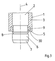
- a conventional, only partially illustrated door handle is provided as a handle 1 according to FIGS. 1 and 2, which has an insert part 2 made of steel, for example, and a neck section 3 which is made of plastic existing sheathing of the insert 2 is formed and has, for example, a cylindrical contour with an axis 4.
- the axis 4 in the assembled state of the device is the common longitudinal axis of all parts and at the same time the axis of rotation for the handle 1.
- the neck section 3 ends on an end face 5.
- the device also has a bearing part 11, which is preferably formed in two parts and consists of a e.g. made of plastic lower part 12 and an upper part 14 made of steel.
- the lower part 12 which can be seen in particular in FIGS. 4 to 8, is placed with its lower or rear broad side in FIG. 1 on a door leaf, a wall or the like, while the upper part 14, which is shown in particular in FIGS. 9 to 11, comes with its bottom or back on the top or front of the lower part 12 to lie.
- both parts 12, 14 are preferably circular and are formed as thin, essentially plane-parallel disks.
- both parts 12, 14 have screw holes 15, 16 which can be aligned with one another for fastening screws, threaded sleeves or the like.
- the lower part 12 and the upper part 14 are also provided with cylindrical passages 17, 18 which are to be aligned coaxially with one another and coaxially with the axis 4 and which serve to receive the bearing section 6 and have a diameter substantially corresponding to the diameter of the bearing section 6.
- the passage 18 of the upper part 14 is surrounded by a bearing collar 19 which protrudes upwards or from the upper or front side of the upper part 14 and expediently forms a circumferential, closed bearing surface.
- the upper part 14 has a downwardly projecting, e.g. cylindrical peripheral wall 20 which, in the assembled state, i.e. when the lower part 12 is inserted into it (FIG. 1), the circumferential surface of which engages with a clamp fit, and the height of which is such that it is flush with the underside of the lower part 12 in the assembled state.
- the peripheral wall 20 is provided with two sector-shaped cutouts 21 (FIGS. 9, 10) which, when the lower part 12 is inserted, receive two correspondingly sector-shaped projections 22 provided on the edge thereof and having undercuts 23 (FIG. 1) on their outer circumference. These interact with the undercuts assigned to them on the inner lateral surface of a cover cap 24 which, after the mounting of the bearing part 11, is placed thereon in the manner shown in FIG to cover the outside.
- a groove 25 (FIG. 6) coaxial with the axis of the passage 17 is machined into the underside of the lower part 12, through which a peripheral wall section 26 with a reduced wall thickness adjoining the passage 17 is formed. This is divided by slots 27 parallel to the axis of the passage 17 into a plurality of resilient slats 28 (FIGS. 6 and 8), which can be pivoted to a limited extent in the radial direction around their base sections due to the small wall thickness.
- the depth of the groove 25 is itself freely selectable and extends, for example, over one or two thirds of the thickness of the lower part 12.
- the peripheral bearing groove 9 of the handle 1 has, as shown in particular in FIGS. 1 and 3, a diameter which essentially corresponds to the diameter of the bearing collar 19.
- the bearing groove 9 preferably has a slightly larger width than the wall thickness of the bearing collar 19 of the upper part 14.
- the depth of the bearing groove 9 corresponds essentially to the height of the bearing collar 19 or somewhat more.
- the bearing collar 19 can be arranged essentially coaxially in the bearing groove 9 with the usual bearing play.
- the bearing groove 9 serves the purpose that the upper part 14 can perform limited tilting movements relative to the axis 4 when the bearing collar 19 is inserted into the bearing groove 9.
- a radially inner inner wall 30 (FIG.
- the neck section 3 delimiting the bearing groove 9 is preferably of slightly conical or frustoconical shape, its diameter gradually decreasing towards the free end.
- the inner diameter of the bearing collar 19 corresponds approximately to the diameter of the inner wall 30 at a location near the bottom of the bearing groove 9.
- the bearing part 11 is first attached to a door leaf, not shown, by the screw holes 15, 16 as well as the cutouts 21 and the shoulders 22 of the lower and upper parts 12, 14 are correspondingly aligned with one another and fastening elements 31 shown in FIG. 2 are inserted into the screw holes 15, 16.
- the cover cap 24 is then clipped on in accordance with FIG. 1.
- the parts 12, 14 and 24 form a rosette, the free ends of the slats 28 facing the door leaf with the required small distance, while the bearing collar 19 protrudes upward or slightly from a receiving opening 32 of the cover cap 24.
- the bearing section 6 of the handle 1 is now inserted axially into the passages 17, 18 (FIGS. 6 and 9) until the bearing collar 19 is completely received in the bearing groove 9 and the front end of the neck section 3 in the receiving opening 32 (Fig. 12).
- the bearing collar 19 lies with the usual bearing play in the bearing groove 9, while at the same time the bearing section 6 coaxially in the passage 17 of the lower part 12 formed by the lamellae 28 is stored.
- the axis 4 of the handle 1 or the actuating element 10 is inclined at an angle ⁇ to the bearing axis, for example because a corresponding rosette on the other side of the door relative to the rosette shown in FIGS. 1 and 12 with a small lateral offset or that from FIG. 1 and 12 visible rosette with a small radial offset relative to an axis of rotation specified by a lock nut or the like.
- the handle 1 can be inclined accordingly with its axis 4.
- the inner wall 30 can pivot relative to the bearing collar 19 due to the increased width of the bearing groove 9 or its conical configuration, while on the other hand the bearing section 6 is pivotably mounted in the area of the lamellae 28.
- the only requirement is that the inside diameter of the section of the passage 17 not provided with the lamella 28 and the inside diameter of the passage 18 of the upper part 14, where they interact with the bearing section 6, each have a slightly larger diameter than the bearing section 6 or that the respective material properties (eg plastic) allow such swiveling due to elastic deformation.
- the handle 1 is rotatably mounted in such pivot positions at two locations arranged at a comparatively large distance, namely on the one hand by means of the bearing collar 19 on the inner wall 30 and on the other hand by means of the bearing section 6 in the lower part 12.
- the bearing point mentioned first acts like a self-aligning bearing, which also allows the usual rotary movements of the handle 1, while the other bearing acts as an elastic compensating bearing.
- ⁇ which is 1.5 ° and a total of 3 °, for example on both sides of the axis 4, this results in a stable and safe even in the case of assembly inaccuracies which are the cause of such slight pivoting of the axis 4 relative to the bearing axis Rotary bearing of the equipment part.
- the described type of mounting of the equipment part 1 is used with particular advantage in combination with the device explained below for axially immovable fastening of the handle 1 on the bearing part 11.
- the lower part 12 has on its top or front side a recess 35 surrounding the passage 17 (FIG. 5) with a bottom 36, which in the is arranged substantially parallel to the lower or rear side of the lower part 12.
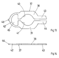
- the recess 35 serves to receive an expansion part 37 (FIGS. 2, 13, 14), which preferably consists of a sheet-metal stamped part produced in one piece.
- the expansion part 37 has two mirror-opposite, substantially parallel arms 38, 39, which are provided in a central region with concave cutouts 40, 41, the mutually facing surfaces of which, for example, have a shape adapted to the circumferential surface of the bottom of the circumferential groove 8 of the bearing section 6 (Fig. 3).
- the thickness of the arms 38, 39 is at least in this area smaller than the width of the circumferential groove 8.
- the two arms 38, 39 are connected to one another by an at least partially elastically bendable web 42 and at the opposite, free end to end sections 43, 44 provided, which are arranged in the normal state with a suitable and certain distance for the insertion of a tool, for example a screwdriver, so that the expansion part 37 is generally substantially U-shaped.
- the opposing surfaces of the cutouts 40, 41 are normally held at a distance from one another by the web 42 which is smaller than the diameter of the bearing section 6 outside the region the circumferential groove 8.
- an eyelet-like recess 45 serving for assembly and an extension 46 projecting outwards are preferably provided.
- the expansion part 37 can be inserted into the recess 35 of the lower part 12 in such a way that the recess 45 is penetrated by a protrusion 47 projecting from the bottom 36 of the recess 35 and at the same time the extension 46 in a slot opening 48 comes to rest, which is arranged in the wall surrounding the recess 35.
- the expansion part 37 is largely immovable and non-pivotable in the recess 35.
- the projection 47 is flush with the front of the lower part 12, while the thickness of the expansion part 37 is somewhat smaller than the depth of the recess 35.
- the bottom 36 of the recess 35 is provided with an additional recess 49 (FIGS. 1, 4, 7) which is preferably pivotable Recording a securing element 50 (Fig. 1, 2, 15 to 17) is used. 1 and 7, the recess 49 has a depth that increases radially outwards from the passage 17 of the lower part 12 and thus has a sloping bottom 51, which in one area directly adjoining the passage 17 also has one to it Has axis parallel groove 52 (Fig. 4 and 7).
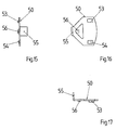
- the securing element 50 preferably consists of a one-piece sheet-metal stamped part and has on its upper side two locking lugs 53, 54 which are opposite one another at a distance which essentially corresponds to the distance between the outer edges of the end sections 43, 44 of the expansion part 37 in its normal state (FIG . 21).
- the securing element 50 At its end coming radially inward in the recess 49, the securing element 50 is provided with a tab 55 which is angled downward by approximately 90 ° and is dimensioned such that it fits into the groove 52 of the lower part 12 and radially obliquely into the Passage 17 of the lower part 12 protrudes when the securing element 50 lies freely on the bottom 51 of the recess 49 (FIG. 1). Finally, the securing element 50 is also provided with a projection 56 protruding from its upper side, which is assigned to the end sections 43, 44 of the expansion part 37 and has a width which is somewhat larger than the free space between these two end sections 43, 44 (FIG. 13) is in the normal state of the expansion element 37.
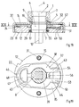
- An unlocking hole 57 formed in the upper part 14 is used to actuate the expansion element 37 from the outside, which in the exemplary embodiment is arranged parallel but at a radial distance from the axis of the passage 18 and the meaning of which is explained below.
- the securing element 50 is first positioned on the bottom 51 of the recess 49 of the lower part 12 such that the tab 55 is arranged in the region of the groove 52 and protrudes somewhat into the cross section of the passage 17 (FIG. 1). Then the expansion part 37 is placed in the recess 35 (FIG. 2) such that its shoulder 46 enters the slot opening 48, its recess 45 is protruded by the projection 47 and the two end sections 43, 44 of the arms 38, 39 on the securing element 50 come to rest. In this position, the end sections 43, 44 assume the position according to FIG.
- the handle 1 is mounted immediately or at a later time. For this purpose, this is inserted in the manner shown in FIGS. 1 and 2 with the bearing section 6 ahead into the coaxially aligned passages 17, 18, the insertion section 7 entering the space formed by the cutouts 40 and 41 of the expansion part 37 and in the further Advancing the bearing section 6 causes a radial and elastic spreading of the arms 38, 39. The arms 38, 39 then run onto the bearing section 6 (FIG. 2).
- the locking lugs 53, 54 come into a position in which they lie tightly against the associated end sections 43, 44 of the expansion part 37 from the outside, thereby preventing a renewed, now undesired radial spreading of the arms 38, 39 by positive locking.
- the space for the expansion part 37 between the rear of the upper part 14 and the bottom 36 of the recess 35 can be dimensioned as narrowly as is just sufficient for easy expansion of the expansion part 37, the expansion part can also be prevented in a simple manner 37 can be moved unintentionally by axial displacement or pivoting out of the blocking zone formed by the locking lugs 53, 54 and the positive Locking is unintentionally released.
- bearing section 6 is now rotatable, but axially essentially immovable in the bearing part 11.
- the cover cap 24 is first separated from the bearing part 11 and pulled back on the neck portion 3 of the handle 1 and rotated so that the unlocking hole 57 is exposed. Then a tool, e.g. a screwdriver with a broad blade, an angle element made of flat iron or the like, is inserted into the now visible part 58 (FIG. 21) of the space between the end sections 43, 44 and is first pressed axially against the securing element 50, around which the locking lugs 53, 54 containing section to pivot elastically relative to the tab 55 and to push deeper into the recess 49.
- a tool e.g. a screwdriver with a broad blade, an angle element made of flat iron or the like
- the end sections 43, 44 of the expansion part 37 come out of the effective range of the locking lugs 53, 54 and can therefore now e.g. by rotating the tool into a position analogous to FIGS. 2 and 19, respectively, until they have emerged completely from the circumferential groove 8 of the bearing section 6.
- the handle 1 can now be pulled out of the passages 17, 18, the tab 55 automatically coming back into the position 17 projecting into the passage 17 due to the elastic prestress.
- the unlocking hole 57 therefore allows on the one hand a visual control of the function of the expansion part 37 and securing element 50 and on the other hand the introduction of a tool from the outside for direct removal of the handle 1 from the bearing part 11, without the need for additional expansion slides or the like.
- the invention is not limited to the exemplary embodiment described, which can be modified in many ways.
- the bearing part 11 in one piece, in which, for example, the bearing collar 19 is molded directly onto the lower part 12 and the expansion part 37 is held in position on its front side by a round disc or the cover cap 24, the unlocking hole 57 being formed either in the disc or in the cover cap 24 and possibly could be closed with a stopper.
- the bearing collar 19 could be provided with slots or recesses through which the expansion part 37 could enter the circumferential groove 8.
Landscapes
- Engineering & Computer Science (AREA)
- Mechanical Engineering (AREA)
- Lock And Its Accessories (AREA)
- Window Of Vehicle (AREA)
- Wing Frames And Configurations (AREA)
- Sliding-Contact Bearings (AREA)
- Snaps, Bayonet Connections, Set Pins, And Snap Rings (AREA)
- Pivots And Pivotal Connections (AREA)
- Hinges (AREA)
Applications Claiming Priority (2)
| Application Number | Priority Date | Filing Date | Title |
|---|---|---|---|
| DE29511547U DE29511547U1 (de) | 1995-07-19 | 1995-07-19 | Vorrichtung zur axial unverschieblichen, lösbaren Befestigung einer Handhabe an einem Lagerteil, insbesondere für Türdrücker, Fenstergriffe o.dgl. |
| DE29511547U | 1995-07-19 |
Publications (3)
| Publication Number | Publication Date |
|---|---|
| EP0754827A2 true EP0754827A2 (fr) | 1997-01-22 |
| EP0754827A3 EP0754827A3 (fr) | 1998-04-01 |
| EP0754827B1 EP0754827B1 (fr) | 2006-11-08 |
Family
ID=8010638
Family Applications (1)
| Application Number | Title | Priority Date | Filing Date |
|---|---|---|---|
| EP96111472A Expired - Lifetime EP0754827B1 (fr) | 1995-07-19 | 1996-07-17 | Dispositif pour la fixation amovible et axialement non coulissante d'une poignée sur un élément de palier, notamment pour une poignée de porte ou fenêtre |
Country Status (5)
| Country | Link |
|---|---|
| EP (1) | EP0754827B1 (fr) |
| AT (1) | ATE344865T1 (fr) |
| DE (2) | DE29511547U1 (fr) |
| DK (1) | DK0754827T3 (fr) |
| ES (1) | ES2277337T3 (fr) |
Cited By (5)
| Publication number | Priority date | Publication date | Assignee | Title |
|---|---|---|---|---|
| EP1116838A1 (fr) * | 2000-01-17 | 2001-07-18 | Hewi Heinrich Wilke Gmbh | Ferrure de protection pour porte |
| EP1460203A1 (fr) * | 2003-03-17 | 2004-09-22 | Jado Ag | Dispositif pour la fixation amovible et axiale d'une poignée sur un élément de palier, par example ensemble de poignée de porte ou fenêtre |
| WO2004090268A3 (fr) * | 2003-04-07 | 2004-12-16 | Fix Ab | Agencement poignee |
| GB2410765A (en) * | 2004-02-09 | 2005-08-10 | Middleton Colin Sidney | Handle assembly with latching means to retain handle |
| EP1722113A3 (fr) * | 2003-03-07 | 2008-01-23 | Zamet S.R.L. | Circlip et mécanisme pour poignées avec un tel circlip |
Families Citing this family (6)
| Publication number | Priority date | Publication date | Assignee | Title |
|---|---|---|---|---|
| DE19834691A1 (de) | 1998-07-31 | 2000-02-03 | Wilke Heinrich Hewi Gmbh | Schließsystem |
| DE19939892A1 (de) | 1999-08-23 | 2001-03-01 | Wilke Heinrich Hewi Gmbh | Adapterelement für Türen |
| IT1310070B1 (it) * | 1999-10-21 | 2002-02-05 | Zamet S R L | Dispositivo di collegamento di una maniglia ad un'anta di unserramento e metodo per l'installazione di una maniglia attuabile con |
| EP1739631B1 (fr) | 2005-06-24 | 2012-10-24 | Assa Abloy Ab | Serrure cylindrique modulaire |
| DE102005057766B3 (de) * | 2005-12-02 | 2007-07-05 | Igor Vanjin | Beschlag für Türen, Fenster oder dergleichen |
| DE202013102991U1 (de) | 2013-07-08 | 2014-02-14 | Erich Dieckmann Gmbh | Griffgarnitur |
Family Cites Families (8)
| Publication number | Priority date | Publication date | Assignee | Title |
|---|---|---|---|---|
| GB606209A (en) * | 1946-01-10 | 1948-08-10 | Herbert George Smith | Improved means for attaching knobs or handle levers to roses or door plates |
| GB701879A (en) * | 1952-03-05 | 1954-01-06 | Lilly & Sons Ltd B | Improvements relating to handle assemblies for doors |
| FR2317451A1 (fr) * | 1975-07-09 | 1977-02-04 | Ferco Int Usine Ferrures | Poignee sur rosette pour fenetres, portes ou similaires |
| DE2735631B2 (de) * | 1977-08-06 | 1980-11-13 | Wilh. Engstfeld Gmbh U. Co Kg, 5628 Heiligenhaus | Rast- und Rückstellvorrichtung |
| DE3032375A1 (de) * | 1980-08-28 | 1982-09-30 | Gebrüder Goldschmidt Baubeschläge GmbH, 5628 Heiligenhaus | Beschlag, insbesondere fuer fenster |
| DE3604115C2 (de) * | 1985-03-01 | 1994-06-23 | Rudolf Wilke | Türdrückeranordnung |
| DE8809585U1 (de) * | 1988-07-27 | 1988-12-01 | Gebrüder Goldschmidt Baubeschläge GmbH, 5628 Heiligenhaus | Beschlag für Fenster oder Türen |
| DE8908282U1 (de) * | 1989-07-07 | 1990-05-03 | Hoppe Gmbh & Co Kg, 3570 Stadtallendorf | Drehhandhabe |
-
1995
- 1995-07-19 DE DE29511547U patent/DE29511547U1/de not_active Expired - Lifetime
-
1996
- 1996-07-17 AT AT96111472T patent/ATE344865T1/de not_active IP Right Cessation
- 1996-07-17 ES ES96111472T patent/ES2277337T3/es not_active Expired - Lifetime
- 1996-07-17 DE DE59611399T patent/DE59611399D1/de not_active Expired - Fee Related
- 1996-07-17 DK DK96111472T patent/DK0754827T3/da active
- 1996-07-17 EP EP96111472A patent/EP0754827B1/fr not_active Expired - Lifetime
Cited By (6)
| Publication number | Priority date | Publication date | Assignee | Title |
|---|---|---|---|---|
| EP1116838A1 (fr) * | 2000-01-17 | 2001-07-18 | Hewi Heinrich Wilke Gmbh | Ferrure de protection pour porte |
| EP1722113A3 (fr) * | 2003-03-07 | 2008-01-23 | Zamet S.R.L. | Circlip et mécanisme pour poignées avec un tel circlip |
| EP1460203A1 (fr) * | 2003-03-17 | 2004-09-22 | Jado Ag | Dispositif pour la fixation amovible et axiale d'une poignée sur un élément de palier, par example ensemble de poignée de porte ou fenêtre |
| WO2004090268A3 (fr) * | 2003-04-07 | 2004-12-16 | Fix Ab | Agencement poignee |
| GB2410765A (en) * | 2004-02-09 | 2005-08-10 | Middleton Colin Sidney | Handle assembly with latching means to retain handle |
| GB2410765B (en) * | 2004-02-09 | 2005-12-21 | Middleton Colin Sidney | Improvements in door furniture |
Also Published As
| Publication number | Publication date |
|---|---|
| DK0754827T3 (da) | 2007-03-19 |
| DE29511547U1 (de) | 1996-11-21 |
| ATE344865T1 (de) | 2006-11-15 |
| EP0754827A3 (fr) | 1998-04-01 |
| ES2277337T3 (es) | 2007-07-01 |
| EP0754827B1 (fr) | 2006-11-08 |
| DE59611399D1 (de) | 2006-12-21 |
Similar Documents
| Publication | Publication Date | Title |
|---|---|---|
| DE60100608T2 (de) | Wasserdichte Halteöse | |
| DE19521744C2 (de) | Befestigungsanordnung mit Schraube für hohes Drehmoment und Durchführung | |
| AT404858B (de) | Als scharniertopf ausgebildeter tür-anschlagteil für möbelscharniere | |
| EP0231440B1 (fr) | Pare-soleil pour véhicules | |
| DE19728641A1 (de) | Positionsscharnier für Türen | |
| EP3276186A1 (fr) | Bouchon à vis | |
| EP0840336B1 (fr) | Commutateur à poussoir autoréglable, en particulier un contacteur de stop | |
| DE9311243U1 (de) | Drehverschluß | |
| EP0754827B1 (fr) | Dispositif pour la fixation amovible et axialement non coulissante d'une poignée sur un élément de palier, notamment pour une poignée de porte ou fenêtre | |
| DE4006707C2 (de) | Vorreiberverschluß | |
| EP0601446A1 (fr) | Dispositif de verrouillage pour un dispositif de drainage | |
| DE29923492U1 (de) | Scharnier | |
| EP4012200B1 (fr) | Boulon d'encliquetage sollicité par ressort | |
| EP1132560B1 (fr) | Charnière et procédé de réglage en hauteur d'une charnière | |
| EP0340456B1 (fr) | Palier de compas pour fenêtre oscillo-battante | |
| DE3604115A1 (de) | Tuerdrueckeranordnung | |
| DE10037550A1 (de) | Kabelanschlussvorrichtung | |
| EP0754826A2 (fr) | Dispositif de palier pour poignée de porte | |
| EP0791759A1 (fr) | Boulon à connexion rapide | |
| EP0837252B1 (fr) | Elément de fixation | |
| EP3363969A1 (fr) | Poignée d'actionnement | |
| DE102017109483A1 (de) | Drehverschluss | |
| DE3143638A1 (de) | Schliesszylinder | |
| EP1213495A2 (fr) | Montage de ressort à lame et dispositif de fixation pour le raccordement démontable de deux éléments | |
| DE9002502U1 (de) | Vorreiberverschluß |
Legal Events
| Date | Code | Title | Description |
|---|---|---|---|
| PUAI | Public reference made under article 153(3) epc to a published international application that has entered the european phase |
Free format text: ORIGINAL CODE: 0009012 |
|
| AK | Designated contracting states |
Kind code of ref document: A2 Designated state(s): AT BE CH DE DK ES FR GB IT LI LU NL SE |
|
| PUAL | Search report despatched |
Free format text: ORIGINAL CODE: 0009013 |
|
| AK | Designated contracting states |
Kind code of ref document: A3 Designated state(s): AT BE CH DE DK ES FR GB IT LI LU NL SE |
|
| 17P | Request for examination filed |
Effective date: 19980921 |
|
| 17Q | First examination report despatched |
Effective date: 20030804 |
|
| RTI1 | Title (correction) |
Free format text: DEVICE FOR RELEASABLE AND NON-SLIDING MOUNTING OF A HANDLE ON A BEARING ELEMENT, ESPECIALLY FOR DOOR HANDLES OR WINDOW HANDLES |
|
| GRAP | Despatch of communication of intention to grant a patent |
Free format text: ORIGINAL CODE: EPIDOSNIGR1 |
|
| GRAS | Grant fee paid |
Free format text: ORIGINAL CODE: EPIDOSNIGR3 |
|
| GRAA | (expected) grant |
Free format text: ORIGINAL CODE: 0009210 |
|
| AK | Designated contracting states |
Kind code of ref document: B1 Designated state(s): AT BE CH DE DK ES FR GB IT LI LU NL SE |
|
| REG | Reference to a national code |
Ref country code: GB Ref legal event code: FG4D Free format text: NOT ENGLISH |
|
| REG | Reference to a national code |
Ref country code: CH Ref legal event code: EP |
|
| REF | Corresponds to: |
Ref document number: 59611399 Country of ref document: DE Date of ref document: 20061221 Kind code of ref document: P |
|
| REG | Reference to a national code |
Ref country code: CH Ref legal event code: NV Representative=s name: E. BLUM & CO. PATENTANWAELTE |
|
| REG | Reference to a national code |
Ref country code: SE Ref legal event code: TRGR |
|
| GBT | Gb: translation of ep patent filed (gb section 77(6)(a)/1977) |
Effective date: 20070201 |
|
| REG | Reference to a national code |
Ref country code: DK Ref legal event code: T3 |
|
| ET | Fr: translation filed | ||
| REG | Reference to a national code |
Ref country code: ES Ref legal event code: FG2A Ref document number: 2277337 Country of ref document: ES Kind code of ref document: T3 |
|
| PLBE | No opposition filed within time limit |
Free format text: ORIGINAL CODE: 0009261 |
|
| STAA | Information on the status of an ep patent application or granted ep patent |
Free format text: STATUS: NO OPPOSITION FILED WITHIN TIME LIMIT |
|
| REG | Reference to a national code |
Ref country code: CH Ref legal event code: PFA Owner name: HEWI HEINRICH WILKE GMBH Free format text: HEWI HEINRICH WILKE GMBH#PROF.-BIER-STRASSE 1-5#34454 BAD AROLSEN (DE) -TRANSFER TO- HEWI HEINRICH WILKE GMBH#PROF.-BIER-STRASSE 1-5#34454 BAD AROLSEN (DE) |
|
| 26N | No opposition filed |
Effective date: 20070809 |
|
| PGFP | Annual fee paid to national office [announced via postgrant information from national office to epo] |
Ref country code: ES Payment date: 20080821 Year of fee payment: 13 Ref country code: DK Payment date: 20080721 Year of fee payment: 13 |
|
| PGFP | Annual fee paid to national office [announced via postgrant information from national office to epo] |
Ref country code: IT Payment date: 20080728 Year of fee payment: 13 |
|
| PGFP | Annual fee paid to national office [announced via postgrant information from national office to epo] |
Ref country code: GB Payment date: 20080723 Year of fee payment: 13 |
|
| PGFP | Annual fee paid to national office [announced via postgrant information from national office to epo] |
Ref country code: SE Payment date: 20080709 Year of fee payment: 13 |
|
| PGFP | Annual fee paid to national office [announced via postgrant information from national office to epo] |
Ref country code: FR Payment date: 20090722 Year of fee payment: 14 |
|
| PGFP | Annual fee paid to national office [announced via postgrant information from national office to epo] |
Ref country code: NL Payment date: 20090726 Year of fee payment: 14 Ref country code: LU Payment date: 20090728 Year of fee payment: 14 Ref country code: DE Payment date: 20090903 Year of fee payment: 14 Ref country code: CH Payment date: 20090727 Year of fee payment: 14 Ref country code: AT Payment date: 20090729 Year of fee payment: 14 |
|
| PGFP | Annual fee paid to national office [announced via postgrant information from national office to epo] |
Ref country code: BE Payment date: 20090729 Year of fee payment: 14 |
|
| REG | Reference to a national code |
Ref country code: DK Ref legal event code: EBP |
|
| EUG | Se: european patent has lapsed | ||
| GBPC | Gb: european patent ceased through non-payment of renewal fee |
Effective date: 20090717 |
|
| PG25 | Lapsed in a contracting state [announced via postgrant information from national office to epo] |
Ref country code: GB Free format text: LAPSE BECAUSE OF NON-PAYMENT OF DUE FEES Effective date: 20090717 |
|
| PG25 | Lapsed in a contracting state [announced via postgrant information from national office to epo] |
Ref country code: DK Free format text: LAPSE BECAUSE OF NON-PAYMENT OF DUE FEES Effective date: 20090731 |
|
| REG | Reference to a national code |
Ref country code: ES Ref legal event code: FD2A Effective date: 20090718 |
|
| PG25 | Lapsed in a contracting state [announced via postgrant information from national office to epo] |
Ref country code: ES Free format text: LAPSE BECAUSE OF NON-PAYMENT OF DUE FEES Effective date: 20090718 |
|
| BERE | Be: lapsed |
Owner name: HEWI HEINRICH WILKE G.M.B.H. Effective date: 20100731 |
|
| REG | Reference to a national code |
Ref country code: NL Ref legal event code: V1 Effective date: 20110201 |
|
| REG | Reference to a national code |
Ref country code: CH Ref legal event code: PL |
|
| PG25 | Lapsed in a contracting state [announced via postgrant information from national office to epo] |
Ref country code: IT Free format text: LAPSE BECAUSE OF NON-PAYMENT OF DUE FEES Effective date: 20090717 |
|
| REG | Reference to a national code |
Ref country code: FR Ref legal event code: ST Effective date: 20110331 |
|
| PG25 | Lapsed in a contracting state [announced via postgrant information from national office to epo] |
Ref country code: LI Free format text: LAPSE BECAUSE OF NON-PAYMENT OF DUE FEES Effective date: 20100731 Ref country code: DE Free format text: LAPSE BECAUSE OF NON-PAYMENT OF DUE FEES Effective date: 20110201 Ref country code: CH Free format text: LAPSE BECAUSE OF NON-PAYMENT OF DUE FEES Effective date: 20100731 |
|
| REG | Reference to a national code |
Ref country code: DE Ref legal event code: R119 Ref document number: 59611399 Country of ref document: DE Effective date: 20110201 |
|
| PG25 | Lapsed in a contracting state [announced via postgrant information from national office to epo] |
Ref country code: FR Free format text: LAPSE BECAUSE OF NON-PAYMENT OF DUE FEES Effective date: 20100802 Ref country code: SE Free format text: LAPSE BECAUSE OF NON-PAYMENT OF DUE FEES Effective date: 20090718 Ref country code: AT Free format text: LAPSE BECAUSE OF NON-PAYMENT OF DUE FEES Effective date: 20100717 Ref country code: NL Free format text: LAPSE BECAUSE OF NON-PAYMENT OF DUE FEES Effective date: 20110201 |
|
| PG25 | Lapsed in a contracting state [announced via postgrant information from national office to epo] |
Ref country code: BE Free format text: LAPSE BECAUSE OF NON-PAYMENT OF DUE FEES Effective date: 20100731 |
|
| PG25 | Lapsed in a contracting state [announced via postgrant information from national office to epo] |
Ref country code: LU Free format text: LAPSE BECAUSE OF NON-PAYMENT OF DUE FEES Effective date: 20100717 |