EP0754912B1 - Procédé de combustion et appareil pour sa mise en oeuvre avec injection séparée du combustible et du carburant - Google Patents
Procédé de combustion et appareil pour sa mise en oeuvre avec injection séparée du combustible et du carburant Download PDFInfo
- Publication number
- EP0754912B1 EP0754912B1 EP96401578A EP96401578A EP0754912B1 EP 0754912 B1 EP0754912 B1 EP 0754912B1 EP 96401578 A EP96401578 A EP 96401578A EP 96401578 A EP96401578 A EP 96401578A EP 0754912 B1 EP0754912 B1 EP 0754912B1
- Authority
- EP
- European Patent Office
- Prior art keywords
- fuel
- oxidant
- cavities
- further characterized
- fluid
- Prior art date
- Legal status (The legal status is an assumption and is not a legal conclusion. Google has not performed a legal analysis and makes no representation as to the accuracy of the status listed.)
- Expired - Lifetime
Links
- 239000000446 fuel Substances 0.000 title claims description 420
- 239000007800 oxidant agent Substances 0.000 title claims description 251
- 230000001590 oxidative effect Effects 0.000 title claims description 250
- 238000002485 combustion reaction Methods 0.000 title claims description 97
- 238000002347 injection Methods 0.000 title claims description 24
- 239000007924 injection Substances 0.000 title claims description 24
- 239000012530 fluid Substances 0.000 claims description 170
- 239000007788 liquid Substances 0.000 claims description 84
- VNWKTOKETHGBQD-UHFFFAOYSA-N methane Chemical compound C VNWKTOKETHGBQD-UHFFFAOYSA-N 0.000 claims description 68
- 239000001301 oxygen Substances 0.000 claims description 58
- 229910052760 oxygen Inorganic materials 0.000 claims description 58
- QVGXLLKOCUKJST-UHFFFAOYSA-N atomic oxygen Chemical compound [O] QVGXLLKOCUKJST-UHFFFAOYSA-N 0.000 claims description 57
- 239000007789 gas Substances 0.000 claims description 38
- 238000000034 method Methods 0.000 claims description 38
- 239000003345 natural gas Substances 0.000 claims description 33
- 239000000463 material Substances 0.000 claims description 15
- 238000009826 distribution Methods 0.000 claims description 11
- MCMNRKCIXSYSNV-UHFFFAOYSA-N Zirconium dioxide Chemical compound O=[Zr]=O MCMNRKCIXSYSNV-UHFFFAOYSA-N 0.000 claims description 8
- 239000000203 mixture Substances 0.000 claims description 7
- ATUOYWHBWRKTHZ-UHFFFAOYSA-N Propane Chemical compound CCC ATUOYWHBWRKTHZ-UHFFFAOYSA-N 0.000 claims description 6
- 230000005484 gravity Effects 0.000 claims description 4
- 230000007480 spreading Effects 0.000 claims description 4
- 238000003892 spreading Methods 0.000 claims description 4
- PNEYBMLMFCGWSK-UHFFFAOYSA-N aluminium oxide Inorganic materials [O-2].[O-2].[O-2].[Al+3].[Al+3] PNEYBMLMFCGWSK-UHFFFAOYSA-N 0.000 claims description 3
- 230000002093 peripheral effect Effects 0.000 claims description 3
- 239000001294 propane Substances 0.000 claims description 3
- VYPSYNLAJGMNEJ-UHFFFAOYSA-N silicon dioxide Inorganic materials O=[Si]=O VYPSYNLAJGMNEJ-UHFFFAOYSA-N 0.000 claims description 3
- 239000000377 silicon dioxide Substances 0.000 claims description 3
- 239000003949 liquefied natural gas Substances 0.000 claims description 2
- UGFAIRIUMAVXCW-UHFFFAOYSA-N Carbon monoxide Chemical compound [O+]#[C-] UGFAIRIUMAVXCW-UHFFFAOYSA-N 0.000 claims 1
- 229910002091 carbon monoxide Inorganic materials 0.000 claims 1
- 239000001257 hydrogen Substances 0.000 claims 1
- 229910052739 hydrogen Inorganic materials 0.000 claims 1
- 125000004435 hydrogen atom Chemical class [H]* 0.000 claims 1
- 238000000889 atomisation Methods 0.000 description 46
- MWUXSHHQAYIFBG-UHFFFAOYSA-N nitrogen oxide Inorganic materials O=[N] MWUXSHHQAYIFBG-UHFFFAOYSA-N 0.000 description 44
- 239000002737 fuel gas Substances 0.000 description 28
- 239000007921 spray Substances 0.000 description 19
- 239000011521 glass Substances 0.000 description 17
- 230000015572 biosynthetic process Effects 0.000 description 13
- IJGRMHOSHXDMSA-UHFFFAOYSA-N Atomic nitrogen Chemical compound N#N IJGRMHOSHXDMSA-UHFFFAOYSA-N 0.000 description 12
- 230000001965 increasing effect Effects 0.000 description 12
- 239000000295 fuel oil Substances 0.000 description 8
- 230000008569 process Effects 0.000 description 8
- 239000004071 soot Substances 0.000 description 8
- MYMOFIZGZYHOMD-UHFFFAOYSA-N Dioxygen Chemical compound O=O MYMOFIZGZYHOMD-UHFFFAOYSA-N 0.000 description 7
- 239000000919 ceramic Substances 0.000 description 7
- 239000000155 melt Substances 0.000 description 7
- 230000008859 change Effects 0.000 description 6
- 229910052757 nitrogen Inorganic materials 0.000 description 6
- 238000012360 testing method Methods 0.000 description 6
- 238000012546 transfer Methods 0.000 description 6
- 230000003247 decreasing effect Effects 0.000 description 5
- 238000013461 design Methods 0.000 description 5
- 239000000839 emulsion Substances 0.000 description 5
- 239000003546 flue gas Substances 0.000 description 5
- 239000002245 particle Substances 0.000 description 5
- 238000000429 assembly Methods 0.000 description 4
- 230000000712 assembly Effects 0.000 description 4
- 238000001816 cooling Methods 0.000 description 4
- 230000000694 effects Effects 0.000 description 4
- 230000006872 improvement Effects 0.000 description 4
- 238000004519 manufacturing process Methods 0.000 description 4
- 238000002844 melting Methods 0.000 description 4
- 230000008018 melting Effects 0.000 description 4
- 239000002184 metal Substances 0.000 description 4
- 238000002156 mixing Methods 0.000 description 4
- 230000005855 radiation Effects 0.000 description 4
- 238000000926 separation method Methods 0.000 description 4
- 238000010008 shearing Methods 0.000 description 4
- 238000001179 sorption measurement Methods 0.000 description 4
- 239000011449 brick Substances 0.000 description 3
- 239000000571 coke Substances 0.000 description 3
- 238000010438 heat treatment Methods 0.000 description 3
- 239000006060 molten glass Substances 0.000 description 3
- 239000011819 refractory material Substances 0.000 description 3
- 239000000523 sample Substances 0.000 description 3
- 238000005070 sampling Methods 0.000 description 3
- XLYOFNOQVPJJNP-UHFFFAOYSA-N water Substances O XLYOFNOQVPJJNP-UHFFFAOYSA-N 0.000 description 3
- CWYNVVGOOAEACU-UHFFFAOYSA-N Fe2+ Chemical compound [Fe+2] CWYNVVGOOAEACU-UHFFFAOYSA-N 0.000 description 2
- 229910001882 dioxygen Inorganic materials 0.000 description 2
- 238000007254 oxidation reaction Methods 0.000 description 2
- 238000007789 sealing Methods 0.000 description 2
- 230000006641 stabilisation Effects 0.000 description 2
- 238000011105 stabilization Methods 0.000 description 2
- 230000000087 stabilizing effect Effects 0.000 description 2
- 229910001220 stainless steel Inorganic materials 0.000 description 2
- HRQSPGSEYDLAIM-UHFFFAOYSA-N 6-amino-2-phenylbenzo[de]isoquinoline-1,3-dione Chemical compound O=C1C(C2=3)=CC=CC=3C(N)=CC=C2C(=O)N1C1=CC=CC=C1 HRQSPGSEYDLAIM-UHFFFAOYSA-N 0.000 description 1
- OKTJSMMVPCPJKN-UHFFFAOYSA-N Carbon Chemical compound [C] OKTJSMMVPCPJKN-UHFFFAOYSA-N 0.000 description 1
- 238000003723 Smelting Methods 0.000 description 1
- 238000010521 absorption reaction Methods 0.000 description 1
- 230000009286 beneficial effect Effects 0.000 description 1
- 230000033228 biological regulation Effects 0.000 description 1
- 229910052799 carbon Inorganic materials 0.000 description 1
- 229910010293 ceramic material Inorganic materials 0.000 description 1
- 230000004087 circulation Effects 0.000 description 1
- 238000004140 cleaning Methods 0.000 description 1
- 238000000576 coating method Methods 0.000 description 1
- 238000009841 combustion method Methods 0.000 description 1
- 238000009833 condensation Methods 0.000 description 1
- 230000005494 condensation Effects 0.000 description 1
- 230000003750 conditioning effect Effects 0.000 description 1
- 238000007796 conventional method Methods 0.000 description 1
- 230000007797 corrosion Effects 0.000 description 1
- 238000005260 corrosion Methods 0.000 description 1
- 230000003111 delayed effect Effects 0.000 description 1
- 230000001627 detrimental effect Effects 0.000 description 1
- 238000010790 dilution Methods 0.000 description 1
- 239000012895 dilution Substances 0.000 description 1
- KZHJGOXRZJKJNY-UHFFFAOYSA-N dioxosilane;oxo(oxoalumanyloxy)alumane Chemical compound O=[Si]=O.O=[Si]=O.O=[Al]O[Al]=O.O=[Al]O[Al]=O.O=[Al]O[Al]=O KZHJGOXRZJKJNY-UHFFFAOYSA-N 0.000 description 1
- 230000003670 easy-to-clean Effects 0.000 description 1
- 238000005485 electric heating Methods 0.000 description 1
- 230000002708 enhancing effect Effects 0.000 description 1
- 238000001704 evaporation Methods 0.000 description 1
- 230000008020 evaporation Effects 0.000 description 1
- 238000002474 experimental method Methods 0.000 description 1
- 238000001914 filtration Methods 0.000 description 1
- 230000004907 flux Effects 0.000 description 1
- 239000002803 fossil fuel Substances 0.000 description 1
- 239000000156 glass melt Substances 0.000 description 1
- 231100001261 hazardous Toxicity 0.000 description 1
- 239000013529 heat transfer fluid Substances 0.000 description 1
- 238000007689 inspection Methods 0.000 description 1
- 238000009688 liquid atomisation Methods 0.000 description 1
- 238000012423 maintenance Methods 0.000 description 1
- 239000012528 membrane Substances 0.000 description 1
- 239000012768 molten material Substances 0.000 description 1
- 229910052863 mullite Inorganic materials 0.000 description 1
- 239000003921 oil Substances 0.000 description 1
- 238000013021 overheating Methods 0.000 description 1
- 150000002926 oxygen Chemical class 0.000 description 1
- 238000003921 particle size analysis Methods 0.000 description 1
- 230000035515 penetration Effects 0.000 description 1
- 238000011020 pilot scale process Methods 0.000 description 1
- 239000002994 raw material Substances 0.000 description 1
- 230000009257 reactivity Effects 0.000 description 1
- 230000009467 reduction Effects 0.000 description 1
- 230000035939 shock Effects 0.000 description 1
- 238000004904 shortening Methods 0.000 description 1
- HBMJWWWQQXIZIP-UHFFFAOYSA-N silicon carbide Chemical compound [Si+]#[C-] HBMJWWWQQXIZIP-UHFFFAOYSA-N 0.000 description 1
- 229910010271 silicon carbide Inorganic materials 0.000 description 1
- 238000004088 simulation Methods 0.000 description 1
- 239000007787 solid Substances 0.000 description 1
- 239000010935 stainless steel Substances 0.000 description 1
- 238000006467 substitution reaction Methods 0.000 description 1
- 238000004227 thermal cracking Methods 0.000 description 1
- 238000011144 upstream manufacturing Methods 0.000 description 1
- 239000013598 vector Substances 0.000 description 1
- RUDFQVOCFDJEEF-UHFFFAOYSA-N yttrium(III) oxide Inorganic materials [O-2].[O-2].[O-2].[Y+3].[Y+3] RUDFQVOCFDJEEF-UHFFFAOYSA-N 0.000 description 1
Images


Classifications
-
- C—CHEMISTRY; METALLURGY
- C03—GLASS; MINERAL OR SLAG WOOL
- C03B—MANUFACTURE, SHAPING, OR SUPPLEMENTARY PROCESSES
- C03B5/00—Melting in furnaces; Furnaces so far as specially adapted for glass manufacture
- C03B5/16—Special features of the melting process; Auxiliary means specially adapted for glass-melting furnaces
- C03B5/235—Heating the glass
- C03B5/2353—Heating the glass by combustion with pure oxygen or oxygen-enriched air, e.g. using oxy-fuel burners or oxygen lances
-
- F—MECHANICAL ENGINEERING; LIGHTING; HEATING; WEAPONS; BLASTING
- F23—COMBUSTION APPARATUS; COMBUSTION PROCESSES
- F23D—BURNERS
- F23D14/00—Burners for combustion of a gas, e.g. of a gas stored under pressure as a liquid
- F23D14/20—Non-premix gas burners, i.e. in which gaseous fuel is mixed with combustion air on arrival at the combustion zone
- F23D14/22—Non-premix gas burners, i.e. in which gaseous fuel is mixed with combustion air on arrival at the combustion zone with separate air and gas feed ducts, e.g. with ducts running parallel or crossing each other
-
- F—MECHANICAL ENGINEERING; LIGHTING; HEATING; WEAPONS; BLASTING
- F23—COMBUSTION APPARATUS; COMBUSTION PROCESSES
- F23D—BURNERS
- F23D14/00—Burners for combustion of a gas, e.g. of a gas stored under pressure as a liquid
- F23D14/32—Burners for combustion of a gas, e.g. of a gas stored under pressure as a liquid using a mixture of gaseous fuel and pure oxygen or oxygen-enriched air
-
- F—MECHANICAL ENGINEERING; LIGHTING; HEATING; WEAPONS; BLASTING
- F23—COMBUSTION APPARATUS; COMBUSTION PROCESSES
- F23M—CASINGS, LININGS, WALLS OR DOORS SPECIALLY ADAPTED FOR COMBUSTION CHAMBERS, e.g. FIREBRIDGES; DEVICES FOR DEFLECTING AIR, FLAMES OR COMBUSTION PRODUCTS IN COMBUSTION CHAMBERS; SAFETY ARRANGEMENTS SPECIALLY ADAPTED FOR COMBUSTION APPARATUS; DETAILS OF COMBUSTION CHAMBERS, NOT OTHERWISE PROVIDED FOR
- F23M5/00—Casings; Linings; Walls
- F23M5/02—Casings; Linings; Walls characterised by the shape of the bricks or blocks used
- F23M5/025—Casings; Linings; Walls characterised by the shape of the bricks or blocks used specially adapted for burner openings
-
- F—MECHANICAL ENGINEERING; LIGHTING; HEATING; WEAPONS; BLASTING
- F23—COMBUSTION APPARATUS; COMBUSTION PROCESSES
- F23D—BURNERS
- F23D2900/00—Special features of, or arrangements for burners using fluid fuels or solid fuels suspended in a carrier gas
- F23D2900/00012—Liquid or gas fuel burners with flames spread over a flat surface, either premix or non-premix type, e.g. "Flächenbrenner"
- F23D2900/00013—Liquid or gas fuel burners with flames spread over a flat surface, either premix or non-premix type, e.g. "Flächenbrenner" with means for spreading the flame in a fan or fishtail shape over a melting bath
-
- Y—GENERAL TAGGING OF NEW TECHNOLOGICAL DEVELOPMENTS; GENERAL TAGGING OF CROSS-SECTIONAL TECHNOLOGIES SPANNING OVER SEVERAL SECTIONS OF THE IPC; TECHNICAL SUBJECTS COVERED BY FORMER USPC CROSS-REFERENCE ART COLLECTIONS [XRACs] AND DIGESTS
- Y02—TECHNOLOGIES OR APPLICATIONS FOR MITIGATION OR ADAPTATION AGAINST CLIMATE CHANGE
- Y02P—CLIMATE CHANGE MITIGATION TECHNOLOGIES IN THE PRODUCTION OR PROCESSING OF GOODS
- Y02P40/00—Technologies relating to the processing of minerals
- Y02P40/50—Glass production, e.g. reusing waste heat during processing or shaping
Definitions
- the present invention relates to a combustion process and an apparatus therefor containing separate injectors to introduce separately a fuel and an oxidant in the combustion chamber of a furnace, so that the fuel burns with the oxidant in a wide luminous flame, and whereby the combustion of the fuel with the oxidant generates reduced quantities of nitrogen oxides (NO x ).
- the fuel usually contains some nitrogen, and oxygen supplied from non-cryogenic sources, such as oxygen produced by a Vacuum Swing Adsorption plant (VSA), contains a small residual nitrogen concentration.
- VSA Vacuum Swing Adsorption plant
- the emulsion is created mainly by shearing of the jet of liquid fuel by the atomizing fluid.
- the geometry of the outlets for the two fluids completely determines the quality of the atomization, and particle size analysis of the drops resulting from the contact shows a relatively wide diameter distribution (simultaneous presence of small and large particles).
- the inventive burner assembly is characterized by at least one fuel fluid inlet and at least one oxidant fluid inlet, means for transporting the fuel fluid from the fuel inlet to a plurality of fuel outlets, the fuel fluid leaving the fuel outlets in fuel streams that are injected into a combustion chamber, means for transporting the oxidant fluid from the oxidant inlets to at least one oxidant outlet, the oxidant fluid leaving the oxidant outlets in oxidant fluid streams that are injected into the combustion chamber, with the fuel and oxidant outlets being physically separated, and geometrically arranged in order to impart to the fuel fluid streams and the oxidant fluid streams angles (referred to herein as "final" angles) and velocities (as the fuel and oxidant enter the combustion chamber) that allow combustion of the fuel fluid with the oxidant in a stable, wide, and luminous flame.
- Preferred refractory blocks have at least five cavities, three cavities at a lower portion thereof for injection of fuel into a furnace combustion chamber, and two cavities at an upper portion thereof for injection of an oxidant into a furnace combustion chamber.
- the fuel cavities diverge at an initial angle, and then this initial divergence angle increases slightly just before the fuel enters the combustion chamber to the final divergence angle.
- This final divergence angle is preferably only a few degrees larger than the first divergence angle.
- a preferred final angle between two adjacent fuel cavities is between 3 and 10 degrees.
- the distance l between the extremities of the cavities when the fuel enters the combustion chamber of the furnace is comprised preferably between 4 and 10 times the inner diameter d of each fuel injector in the first plane.
- the first plane is preferably but not necessarily parallel to the melt surface.
- the dimension "d" is an equivalent diameter corresponding to the cross-sectional area of an equalivalent circular injector or cavity.
- a process wherein a "sheet" of fuel fluid is generated above the surface to be heated, e.g. by means of at least two fuel cavities that make a final diverging angle preferably smaller than 15 degrees, said fuel cavities being located in a first plane, an oxidant fluid having a lower velocity than that of the fuel fluid (preferably not exceeding 60 meters per second (m/s) being injected above the surface to be heated, preferably with at least two oxygen cavities, two adjacent oxygen cavities making a final diverging angle smaller than 15 degrees.
- These cavities are preferably located in a second plane, which converges to and intersects with the first plane in the combustion chamber.
- a method of combustion in a combustion zone for a burner assembly containing at least two fuel fluid cavities, at least one oxidant fluid cavity and at least one exit face at which the fuel fluid cavities and oxidant fluid cavity terminates, the process entailing:
- the oxidant cavities contain so-called swirlers, intended to give to the oxidant streams a swirling motion to increase the spreading of the oxidant streams in the combustion zone, and improve the mixing between the oxidant and the fuel sheet.
- Suitable swirlers are metallic fins or twisted stripes of metal placed in the cavities or injectors.
- the total quantities of fuel and oxidant used by the combustion system are such that the flow of oxygen ranges from 0.95 to 1.05 of the theoretical stoichiometric flow of oxygen necessary to obtain the complete combustion of the fuel flow. Another expression of this statement is that the combustion ratio is between 0.95 and 1.05.
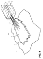
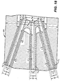
- FIGs. 8a plan view
- 8b end elevation
- 8c side elevation
- the fuel and oxidant cavities are straight holes through refractory block 5.
- the gas exit of each oxidant cavity and each fuel cavity have rounded edges at the gas exit face 10 as opposed to straight edges.
- the rounded edges reduce the velocity gradient between the gas flows ejected from the block and the surrounding atmosphere, which prevents particulates or volatile species contained in the atmosphere to build-up around the outlets of the cavities which in turn would alter the geometry of the cavities. This is particularly important in the case of the natural gas cavities, because the build-up process can be aggravated by the thermal cracking of the natural gas and the formation of coke deposits at the natural gas exits from the refractory blocks, which can alter flow direction in the furnace.
- FIG. 13c is a gas exit end elevation view of an alternate design for the refractory block of FIG. 13a, illustrating an embodiment wherein there are in fact no gaseous fuel exits, and only one liquid fuel exit 97 is present (the two oxidant gas exits are the same as in FIG 13a).
- the inventive liquid fuel atomizer is capable of ensuring the production of a single broad flame, a single long flame, or several short flames simultaneously.
- the axis of the hollow cylinder coincides with that of the hollow cylinder (D FI ; D FE ).
- each of the elementary atomizers is to eject a spray of droplets in a precise direction. This direction is the direction of the axis of the channel and the hollow conduit for liquid fuel.
- the length of the hollow conduit and the length of the channel must be sufficient to secure establishment of the flows of the two fluids in their respective conduits. If one wishes that the two fluids enter the combustion chamber with the same orientation of the axial components of their respective velocity vectors, it is preferred that:
- the atomization device of the invention In the case of continuous use of this device in glass furnaces (combustion chambers with elevated temperatures ranging from 1500°C to 1670°C the atomization device of the invention must be capable of ensuring production of a stable flame for periods on the order of months.
- the atomization principle selected makes it possible to keep the temperature of the metal parts composing the device below 1100°C. Thus, the temperature measured at the tip of the device during an industrial test for one month in a glass furnace at 1600°C never exceeded 800°C.
- this device functions at an atomizing fluid pressure between 1 and 6 bars relative.
- This phenomenon is directly attributable to the change in the particle size distribution of the droplets of liquid fuel composing the spray that is formed: the increase in the rate of delivery of atomizing fluid has the effect of decreasing the average spray droplet diameter and narrowing the distribution of the diameters about this mean value. Conversely, a decrease in the rate of delivery of atomizing fluid will increase the average diameter while widening the distribution.
- FIG. 20a is a schematic illustration of a refractory block 5 and fuel gas cavity 94 in same, while FIG. 20b is a schematic illustrating a cavity throat diameter D' and gas exit diameter D for an injector or cavity.
- the ratio of 1 (from FIG. 2, the distance between adjacent fuel gas exits) and D' (fuel cavity or injector throat diameter) ranges from 1.5 to 10, more preferably from 1.5 to 3, and most preferably 2.
- FIG. 20a also illustrates that the cavities in the refractory block may have varying diameter in the direction of gas flow, and that the gas exits are generally contoured at the exits, allowing the exits to be less likely to be plugged.
Landscapes
- Engineering & Computer Science (AREA)
- Chemical & Material Sciences (AREA)
- Combustion & Propulsion (AREA)
- Mechanical Engineering (AREA)
- General Engineering & Computer Science (AREA)
- Materials Engineering (AREA)
- Organic Chemistry (AREA)
- Combustion Of Fluid Fuel (AREA)
- Air Supply (AREA)
- Nozzles For Spraying Of Liquid Fuel (AREA)
- Pre-Mixing And Non-Premixing Gas Burner (AREA)
Claims (51)
- Procédé de combustion d'un combustible avec un oxydant, comprenant les étapes consistant à:dans lequel l'angle α entre le premier plan de combustible (2) et le deuxième plan d'oxydant (4) est inférieur à 20°.a) fournir une arrivée d'un courant de fluide oxydant;b) injecter une partie majeure dudit courant de fluide oxydant dans une chambre de combustion en au moins deux courants de fluide oxydant;c) fournir une arrivée d'un courant de fluide combustible;d) injecter ledit courant de fluide combustible dans la chambre de combustion de manière à créer au moins deux courants de fluide combustible injectés;
caractérisé par les étapes suivantes:e) créer une nappe de fluide combustible essentiellement plane dans la chambre de combustion avec les au moins deux courants de fluide combustible injectés dans la chambre de combustion, au moins deux des courants de fluide combustible injectés étant essentiellement situés dans un premier plan de combustible (2), la distance h entre le premier plan de combustible et le deuxième plan d'oxydant (4) défini par les au moins deux courants de fluide oxydant étant au moins égale à deux fois le diamètre de l'injecteur d'oxydant (23, 24) dans le plan vertical à la sortie des cavités des courants;f) couper le courant de fluide oxydant avec la nappe de fluide combustible dans la chambre de combustion; etg) brûler le fluide combustible avec le fluide oxydant dans la chambre de combustion; - Procédé suivant la revendication 1, caractérisé en outre en ce que deux courants de fluide combustible voisins présentent un angle de divergence final qui n'est pas supérieur à 15°.
- Procédé suivant la revendication 1 ou 2, caractérisé en outre en ce qu'une partie majeure des courant de fluide combustible est essentiellement située dans le premier plan (2), ledit premier plan se trouvant en dessous desdits courants d'oxydant.
- Procédé suivant l'une quelconque des revendications 1 à 3, caractérisé en outre en ce que tous les courants de fluide combustible sont essentiellement situés dans le premier plan, ledit premier plan de combustible (2) se trouvant en dessous desdits courants d'oxydant.
- Procédé suivant l'une quelconque des revendications 1 à 4, caractérisé en outre en ce que le fluide combustible est un combustible gazeux.
- Procédé suivant l'une quelconque des revendications 1 à 5, caractérisé en outre en ce que ledit fluide combustible est sélectionné parmi le groupe composé du méthane, du gaz naturel, du gaz naturel liquéfié, du gaz naturel reformé à la vapeur, du propane, du monoxyde de carbone, de l'hydrogène, du pétrole atomisé ou de mélanges de ceux-ci.
- Procédé suivant l'une quelconque des revendications 1 à 6, caractérisé en outre en ce que ledit fluide oxydant est un gaz contenant de l'oxygène présentant au moins 50 % en volume d'oxygène.
- Procédé suivant l'une quelconque des revendications 2 à 7, caractérisé en outre en ce que l'angle de divergence final est compris entre 3° et 10°.
- Procédé suivant l'une quelconque des revendications 1 à 8, caractérisé en outre en ce que la totalité de l'oxydant est injecté dans les au moins deux courants de fluide oxydant qui définissent le deuxième plan (4).
- Procédé suivant l'une quelconque des revendications 1 à 9, caractérisé en outre en ce que deux courants de fluide oxydant voisins forment un angle de divergence final inférieur à 15°.
- Procédé suivant l'une quelconque des revendications 1 à 10, caractérisé en outre en ce que l'injection des courants de combustible créent un nuage de combustible qui présente un angle de dispersion qui est au plus égal à 120°.
- Procédé suivant la revendication 11, caractérisé en outre en ce que ledit angle de dispersion est compris entre 10° et 60°.
- Procédé suivant l'une quelconque des revendications 1 à 12, caractérisé en outre en ce que la vitesse du combustible est d'au moins 15 mètres par seconde.
- Procédé suivant l'une quelconque des revendications 1 à 13, dans lequel le premier plan de combustible comprend trois courants de fluide combustible et deux courants de fluide oxydant.
- Procédé suivant l'une quelconque des revendications 1 à 14, dans lequel au moins deux courants de fluide oxydant sont injectés, et une injection de gaz naturel est située entre ces au moins deux courants de fluide oxydant injectés.
- Procédé suivant l'une quelconque des revendications 1 à 15, dans lequel il est prévu une basse pression d'arrivée d'oxydant.
- Procédé suivant l'une quelconque des revendications 1 à 16, dans lequel l'oxydant comprend plus de 50 % en volume d'O2, de préférence plus de 88 % en volume d'O2.
- Ensemble de brûleur comprenant au moins deux cavités de fluide combustible (1a, 1b, 1c ou 20, 22), au moins deux cavités de fluide oxydant (3a, 3b ou 23, 24) et au moins une face de sortie à laquelle au moins deux des cavités de fluide combustible ou au moins deux des cavités de fluide oxydant, ou les deux, aboutissent, l'ensemble de brûleur comprenant en outre:a) des moyens d'arrivée d'un courant de fluide oxydant;b) des moyens d'injection dudit courant de fluide oxydant dans au moins deux cavités de fluide oxydant afin de créer au moins deux courants de fluide oxydant injectés;c) des moyens d'arrivée d'un courant de fluide combustible;d) des moyens d'injection dudit courant de fluide combustible dans au moins deux cavités de fluide combustible afin de créer au moins deux courants de fluide combustible injectés définissant un premier plan de combustible (2), caractérisé en ce que:les directions d'injection du courant de fluide oxydant et du courant de fluide combustible sont essentiellement convergentes avec un angle α compris entre 0° et 20° et se coupent dans une région de combustion, tandis que les directions d'au moins deux cavités de fluide combustible voisines sont divergentes, et la distance h entre le premier plan de combustible et le deuxième plan d'oxydant (4) défini par les au moins deux courants de fluide oxydant est au moins égale à deux fois le diamètre de l'injecteur d'oxydant, dans le plan vertical à la sortie des cavités des courants.
- Ensemble de brûleur suivant la revendication 18, comprenant en outre un bloc réfractaire (5) apte à être en communication fluidique avec des sources d'oxydant et de combustible, le bloc réfractaire (5) présentant une extrémité d'entrée de combustible et d'oxydant et une extrémité de sortie de combustible et d'oxydant, l'extrémité de sortie comportant des sorties de combustible et des sorties d'oxydant, le bloc réfractaire (5) présentant en outre une pluralité de cavités de combustible, au moins deux des cavités de combustible définissant le premier plan de combustible (2), et une pluralité de cavités d'oxydant définissant le deuxième plan d'oxydant (4), les cavités de combustible étant plus nombreuses que les cavités d'oxydant.
- Ensemble de brûleur suivant la revendication 19, caractérisé en outre en ce que les sorties d'oxydant sont plus grandes que les sorties de combustible.
- Ensemble de brûleur suivant la revendication 19 ou 20, caractérisé en outre en ce qu'un ensemble de console de montage (72) est attaché d'une façon amovible sur l'extrémité d'entrée de combustible et d'oxydant du bloc réfractaire, l'ensemble de console de montage comportant une face de distribution de gaz.
- Ensemble de brûleur suivant la revendication 21, caractérisé en outre en ce qu'un distributeur de combustible (74) est positionné sur une partie inférieure de la face de distribution de gaz.
- Ensemble de brûleur suivant la revendication 21 ou 22, caractérisé en outre en ce qu'un distributeur d'oxydant (76) est positionné sur une partie supérieure de la face de distribution de gaz.
- Ensemble de brûleur suivant l'une quelconque des revendications 19 à 23, caractérisé en outre en ce que ledit bloc réfractaire est constitué d'une matière sélectionnée parmi le groupe composé de la zircone fondue, de l'alumine-zircone-silice coulées fondues, de l'alumine-zircone-silice recombinées et de l'alumine coulée fondue.
- Ensemble de brûleur suivant l'une quelconque des revendications 19 à 24, caractérisé en outre ce qu'une ou plusieurs cavité(s) contien(nen)t un injecteur.
- Ensemble de brûleur suivant l'une quelconque des revendications 19 à 25, caractérisé en outre en ce que ledit bloc réfractaire comprend au moins cinq cavités.
- Ensemble de brûleur suivant l'une quelconque des revendications 19 à 26, caractérisé en outre en ce que ledit bloc réfractaire comprend trois cavités (1a, 1b, 1c) à une partie inférieure de celui-ci pour l'injection dudit combustible dans une chambre de combustion de four, et deux cavités (3a, 3b) à une partie supérieure de celui-ci pour l'injection dudit oxydant dans ladite chambre de combustion de four.
- Ensemble de brûleur suivant l'une quelconque des revendications 19 à 27, caractérisé en outre en ce que lesdites sorties de combustible et d'oxydant sont circulaires.
- Ensemble de brûleur suivant l'une quelconque des revendications 19 à 28, caractérisé en outre en ce que lesdites cavités sont des trous traversants droits à travers le bloc réfractaire (5), et en ce que les sorties des cavités sont profilées.
- Ensemble de brûleur suivant l'une quelconque des revendications 27 à 29, caractérisé en outre en ce que lesdites trois cavités à ladite partie inférieure pour l'injection dudit combustible se trouvent chacune à un angle de divergence final à l'extrémité de sortie de combustible et d'oxydant compris entre 3° et 15° par rapport à une cavité de combustible voisine.
- Ensemble de brûleur suivant l'une quelconque des revendications 27 à 30, caractérisé en outre en ce que les trois cavités à ladite partie inférieure pour l'injection dudit combustible se trouvent chacune à un angle de divergence final à l'extrémité de sortie de combustible et d'oxydant compris entre 3° et 10° par rapport à une cavité de combustible voisine.
- Ensemble de brûleur suivant l'une quelconque des revendications 27 à 31, caractérisé en outre en ce que lesdites deux cavités à ladite partie supérieure pour l'injection dudit oxydant sont positionnées à un angle de divergence final entre elles à l'extrémité de sortie de combustible et d'oxydant compris entre 0° et 15°.
- Ensemble de brûleur suivant l'une quelconque des revendications 27 à 32 caractérisé en outre en ce que lesdites deux cavités à ladite partie supérieure pour l'injection dudit oxydant sont positionnées à un angle de divergence final entre elles à l'extrémité de sortie de combustible et d'oxydant compris entre 7° et 15°.
- Ensemble de brûleur suivant l'une quelconque des revendications 23 à 33, caractérisé en outre en ce que ledit distributeur d'oxydant (76) est monté directement sur ledit ensemble de console de montage (72) à l'aide de moyens de fixation.
- Ensemble de brûleur suivant l'une quelconque des revendications 22 à 34, caractérisé en outre en ce que ledit distributeur de combustible (74) est monté directement sur ledit ensemble de console de montage (72) à l'aide de moyens de fixation.
- Ensemble de brûleur suivant l'une quelconque des revendications 27 à 35, caractérisé en outre en ce que ledit distributeur de combustible (74) est un composant intégral unique qui s'adapte à l'intérieur d'une cavité dudit bloc réfractaire (5), ledit distributeur de combustible (74) comportant de multiples sorties de combustible.
- Ensemble de brûleur suivant l'une quelconque des revendications 19 à 36, caractérisé en outre en ce que chaque cavité de combustible comporte une gorge présentant un diamètre de gorge D' ainsi qu'une sortie présentant un diamètre de sortie D', et en ce que les sorties de cavités de combustible sont espacées par une distance l.
- Ensemble de brûleur suivant la revendication 37, caractérisé en outre en ce qu'un rapport de ladite distance l audit diamètre D' de la plus petite des gorges de cavité de combustible est compris entre 1,5 et 10.
- Ensemble de brûleur suivant la revendication 38, caractérisé en outre en ce que ledit rapport est compris entre 1,5 et 3.
- Ensemble de brûleur suivant la revendication 38 ou 39, caractérisé en outre en ce que ledit rapport est égal à 2.
- Ensemble de brûleur suivant l'une quelconque des revendications 19 à 40, caractérisé en outre en ce qu'un rapport de (l/d) est compris entre 4 et 10.
- Ensemble de brûleur suivant l'une quelconque des revendications 19 à 41, caractérisé en outre en ce qu'un rapport de (L/D) est compris entre 2 et 10.
- Ensemble de brûleur suivant l'une quelconque des revendications 19 à 42, caractérisé en outre en ce qu'il comprend au moins un injecteur de combustible liquide positionné en dessous dudit premier plan de combustible à une distance d2, où d2 est défini par:
- IFO =
- la force d'impulsion du combustible liquide dans la cavité ou dans l'injecteur;
- IAIR =
- la force d'impulsion de l'air d'atomisation dans l'injecteur ou dans la cavité;
- ING =
- la force d'impulsion du combustible gazeux;
- ρFO =
- la gravité spécifique du combustible liquide;
- ρNG =
- la gravité spécifique du combustible gazeux, et ledit premier plan de combustible et lesdits deuxièmes plans d'oxydant séparés par une distance d1,
- d1 =
- A(P/1000)½
- Ensemble de brûleur suivant la revendication 43, caractérisé en outre en ce que A est égal à 110 millimètres, et
IFO = 0,06 N;
IAIR = 1,79 N;
ING = 1,56 N;
ρFO = 0,9 kg/dm3;
ρNG = 0,74 kg/m3;
et les valeurs dimensionnelles énumérées dans le Tableau 1, dans lequel d est le diamètre des sorties de combustible gazeux, D est le diamètre des sorties d'oxydant, L est la distance entre les sorties d'oxydant les plus extérieures et l est la distance entre deux sorties quelconques de combustible.Puissance du Brûleur Puissance
(kW)500 1000 1500 2000 3000 4000 5000 6000 7000 D1
(mm)78 110 135 156 191 220 246 270 291 d2
(mm)113 160 196 227 278 320 358 392 423 d
(mm)10,6 15 18,4 21,2 26 30 33,5 36,7 39,7 D
(mm)29,7 42 51,4 59,4 72,7 84 93,9 102,9 111,1 L
(mm)113,1 160 196 226,3 277,1 320 357,8 391,9 423,3 21
(mm)99 140 171,5 198 242,5 280 313 342,9 370,4 - Ensemble de brûleur suivant l'une quelconque des revendications 19 à 44, caractérisé en outre en ce qu'il comprend au moins deux cavités d'oxydant périphériques (91a, 91b) séparées par une distance L, et des cavités de combustible voisines (94) séparées par une distance l, et dans lequel L est plus grand que l d'un facteur d'au moins 2.
- Ensemble de brûleur suivant l'une quelconque des revendications 19 à 45, caractérisé en outre en ce qu'au moins une desdites cavités de fluide combustible (94) dans ledit premier plan de combustible comprend un tube à l'intérieur de ladite cavité (94'), ledit tube présentant un diamètre extérieur sensiblement inférieur au diamètre intérieur de ladite cavité.
- Ensemble de brûleur suivant l'une quelconque des revendications 19 à 46, caractérisé en outre en ce que le deuxième plan d'oxydant et ledit premier plan de combustible sont positionnés de telle sorte qu'ils convergent selon un angle compris entre 0° et 15°.
- Ensemble de brûleur suivant l'une quelconque des revendications 20 à 47, caractérisé en outre en ce qu'au moins une cavité comprend un injecteur positionné à l'intérieur de celle-ci.
- Ensemble de brûleur suivant la revendication 48, dans lequel ledit injecteur fait saillie dans la chambre de combustion.
- Ensemble de brûleur suivant la revendication 48 ou 49, caractérisé en outre en ce que ledit injecteur présente une longueur telle qu'il ne fait pas saillie dans la chambre de combustion, mais qu'il se termine à une position interne dans le bloc réfractaire.
- Ensemble de brûleur suivant l'une quelconque des revendications 19 à 50, comprenant en outre une cavité unique de combustible liquide pour générer un courant de combustible liquide pulvérisé, dans lequel soit un combustible gazeux est injecté en vue de générer les au moins deux courants de fluide combustible, soit un combustible liquide est injecté à travers la cavité unique de combustible liquide en vue de à générer un courant de combustible liquide pulvérisé.
Applications Claiming Priority (4)
| Application Number | Priority Date | Filing Date | Title |
|---|---|---|---|
| US50333695A | 1995-07-17 | 1995-07-17 | |
| US503336 | 1995-07-17 | ||
| US668758 | 1996-06-24 | ||
| US08/668,758 US5984667A (en) | 1995-07-17 | 1996-06-24 | Combustion process and apparatus therefore containing separate injection of fuel and oxidant streams |
Publications (3)
| Publication Number | Publication Date |
|---|---|
| EP0754912A2 EP0754912A2 (fr) | 1997-01-22 |
| EP0754912A3 EP0754912A3 (fr) | 1998-12-16 |
| EP0754912B1 true EP0754912B1 (fr) | 2004-06-09 |
Family
ID=27054469
Family Applications (1)
| Application Number | Title | Priority Date | Filing Date |
|---|---|---|---|
| EP96401578A Expired - Lifetime EP0754912B1 (fr) | 1995-07-17 | 1996-07-16 | Procédé de combustion et appareil pour sa mise en oeuvre avec injection séparée du combustible et du carburant |
Country Status (7)
| Country | Link |
|---|---|
| US (2) | US5833447A (fr) |
| EP (1) | EP0754912B1 (fr) |
| JP (2) | JP3989984B2 (fr) |
| CN (1) | CN1195172C (fr) |
| CA (1) | CA2181292C (fr) |
| DE (1) | DE69632666T2 (fr) |
| ES (1) | ES2220965T3 (fr) |
Families Citing this family (111)
| Publication number | Priority date | Publication date | Assignee | Title |
|---|---|---|---|---|
| EP0754912B1 (fr) * | 1995-07-17 | 2004-06-09 | L'air Liquide, S.A. à Directoire et Conseil de Surveillance pour l'Etude et l'Exploitation des Procédés Georges Claude | Procédé de combustion et appareil pour sa mise en oeuvre avec injection séparée du combustible et du carburant |
| US5975886A (en) * | 1996-11-25 | 1999-11-02 | L'air Liquide, Societe Anonyme Pour L'etude Et L'exploitation Des Procedes Georges Claude | Combustion process and apparatus therefore containing separate injection of fuel and oxidant streams |
| US6071116A (en) | 1997-04-15 | 2000-06-06 | American Air Liquide, Inc. | Heat recovery apparatus and methods of use |
| JP3522506B2 (ja) * | 1997-09-01 | 2004-04-26 | 東京瓦斯株式会社 | 酸素燃焼バーナと該バーナを持つ燃焼炉 |
| FR2777068B1 (fr) * | 1998-04-02 | 2000-05-05 | Air Liquide | Procede de combustion par injections separees du combustible et du comburant |
| EP0967440A3 (fr) | 1998-06-25 | 2002-12-18 | L'air Liquide, S.A. à Directoire et Conseil de Surveillance pour l'Etude et l'Exploitation des Procédés Georges Claude | Système de surveillance et de commande pour la combustion de combustible liquide |
| US6132204A (en) * | 1998-06-30 | 2000-10-17 | Praxair Technology, Inc. | Wide flame burner |
| JP3960444B2 (ja) * | 1998-08-28 | 2007-08-15 | 東京瓦斯株式会社 | 蓄熱燃焼装置 |
| FR2782780B1 (fr) | 1998-09-02 | 2000-10-06 | Air Liquide | Procede de combustion pour bruler un combustible |
| JP3741883B2 (ja) * | 1998-11-20 | 2006-02-01 | 東京瓦斯株式会社 | 酸素燃焼バーナと該バーナを持つ燃焼炉 |
| JP3741884B2 (ja) * | 1998-11-27 | 2006-02-01 | 東京瓦斯株式会社 | 酸素燃焼バーナと該バーナを持つ燃焼炉 |
| DE19914666B4 (de) * | 1999-03-31 | 2009-08-20 | Alstom | Brenner für einen Wärmeerzeuger |
| US6113389A (en) | 1999-06-01 | 2000-09-05 | American Air Liquide, Inc. | Method and system for increasing the efficiency and productivity of a high temperature furnace |
| US6126438A (en) * | 1999-06-23 | 2000-10-03 | American Air Liquide | Preheated fuel and oxidant combustion burner |
| US6705117B2 (en) | 1999-08-16 | 2004-03-16 | The Boc Group, Inc. | Method of heating a glass melting furnace using a roof mounted, staged combustion oxygen-fuel burner |
| US7168269B2 (en) | 1999-08-16 | 2007-01-30 | The Boc Group, Inc. | Gas injection for glass melting furnace to reduce refractory degradation |
| US6422041B1 (en) * | 1999-08-16 | 2002-07-23 | The Boc Group, Inc. | Method of boosting a glass melting furnace using a roof mounted oxygen-fuel burner |
| ATE317529T1 (de) * | 1999-08-17 | 2006-02-15 | Nippon Furnace Kogyo Kk | Verbrennungsverfahren und brenner |
| AU737544B2 (en) * | 1999-10-18 | 2001-08-23 | Air Products And Chemicals Inc. | Method and apparatus for backing-up oxy fuel combustion with air-fuel combustion |
| US6540508B1 (en) | 2000-09-18 | 2003-04-01 | The Boc Group, Inc. | Process of installing roof mounted oxygen-fuel burners in a glass melting furnace |
| AU2001291147A1 (en) | 2000-09-27 | 2002-04-08 | Olivier Charon | Methods and apparatus for combustion in high volatiles environments |
| US6715319B2 (en) * | 2001-03-23 | 2004-04-06 | Pilkington Plc | Melting of glass |
| US7115226B2 (en) * | 2003-06-20 | 2006-10-03 | Mold-Masters Limited | Stack mold having a melt homogenizing element |
| ITMI20032327A1 (it) * | 2003-11-28 | 2005-05-29 | Techint Spa | Bruciatore a gas a basse emissioni inquinanti. |
| FR2863689B1 (fr) * | 2003-12-16 | 2006-05-05 | Air Liquide | Procede de combustion etagee mettant en oeuvre un oxydant prechauffe |
| US7500849B2 (en) * | 2004-01-16 | 2009-03-10 | Air Products And Chemicals, Inc. | Emulsion atomizer nozzle, and burner, and method for oxy-fuel burner applications |
| US7303388B2 (en) | 2004-07-01 | 2007-12-04 | Air Products And Chemicals, Inc. | Staged combustion system with ignition-assisted fuel lances |
| SE528808C2 (sv) * | 2004-09-15 | 2007-02-20 | Aga Ab | Förfarande vid förbränning, jämte brännare |
| FR2879284B1 (fr) * | 2004-12-09 | 2007-01-19 | Air Liquide | Procede de fusion d'une composition de matieres premieres par un bruleur en voute |
| US20070037106A1 (en) * | 2005-08-12 | 2007-02-15 | Kobayashi William T | Method and apparatus to promote non-stationary flame |
| FR2892497B1 (fr) * | 2005-10-24 | 2008-07-04 | Air Liquide | Procede de combustion mixte dans un four a regenerateurs |
| US7581948B2 (en) * | 2005-12-21 | 2009-09-01 | Johns Manville | Burner apparatus and methods for making inorganic fibers |
| US7802452B2 (en) * | 2005-12-21 | 2010-09-28 | Johns Manville | Processes for making inorganic fibers |
| US20070231761A1 (en) * | 2006-04-03 | 2007-10-04 | Lee Rosen | Integration of oxy-fuel and air-fuel combustion |
| US20100159409A1 (en) * | 2006-06-05 | 2010-06-24 | Richardson Andrew P | Non-centric oxy-fuel burner for glass melting systems |
| US20070281264A1 (en) * | 2006-06-05 | 2007-12-06 | Neil Simpson | Non-centric oxy-fuel burner for glass melting systems |
| FR2903478B1 (fr) * | 2006-07-06 | 2008-09-19 | L'air Liquide | Procede de chauffage d'une charge, notamment d'aluminium |
| DE102006060869A1 (de) * | 2006-12-22 | 2008-06-26 | Khd Humboldt Wedag Gmbh | Verfahren zur Regelung des Betriebes eines Drehofenbrenners |
| FR2917155A1 (fr) * | 2007-06-08 | 2008-12-12 | Saint Gobain Emballage Sa | Combustion diluee |
| US8454354B2 (en) * | 2008-05-08 | 2013-06-04 | Air Products And Chemicals, Inc. | Highly radiative burner and combustion process |
| EP2143999A1 (fr) * | 2008-07-08 | 2010-01-13 | L'Air Liquide Société Anonyme pour l'Etude et l'Exploitation des Procédés Georges Claude | Ensemble de brûleur et procédé de combustion |
| RU2474760C2 (ru) * | 2008-08-29 | 2013-02-10 | Л'Эр Ликид Сосьете Аноним Пур Л'Этюд Э Л'Эксплуатасьон Де Проседе Жорж Клод | Способ генерирования горения посредством горелки в сборе и горелка в сборе |
| US8727767B2 (en) | 2009-01-16 | 2014-05-20 | Air Products And Chemicals, Inc. | Multi-mode combustion device and method for using the device |
| US8404018B2 (en) * | 2009-07-06 | 2013-03-26 | Air Products And Chemicals, Inc. | Burner and method for processing oxidizable materials |
| US8172566B2 (en) * | 2010-02-18 | 2012-05-08 | Air Products And Chemicals, Inc. | Liquid fuel combustion process and apparatus |
| US8603203B2 (en) * | 2010-04-12 | 2013-12-10 | Samsung Sdi Co., Ltd. | Burner nozzle assembly and fuel reformer having the same |
| SE1050442A1 (sv) * | 2010-05-04 | 2011-04-26 | Linde Ag | Förfarande för att öka värmehomogeniteten i en gropugn |
| US8707739B2 (en) | 2012-06-11 | 2014-04-29 | Johns Manville | Apparatus, systems and methods for conditioning molten glass |
| US8991215B2 (en) | 2010-06-17 | 2015-03-31 | Johns Manville | Methods and systems for controlling bubble size and bubble decay rate in foamed glass produced by a submerged combustion melter |
| US8973400B2 (en) | 2010-06-17 | 2015-03-10 | Johns Manville | Methods of using a submerged combustion melter to produce glass products |
| US8875544B2 (en) | 2011-10-07 | 2014-11-04 | Johns Manville | Burner apparatus, submerged combustion melters including the burner, and methods of use |
| US8707740B2 (en) | 2011-10-07 | 2014-04-29 | Johns Manville | Submerged combustion glass manufacturing systems and methods |
| US10322960B2 (en) | 2010-06-17 | 2019-06-18 | Johns Manville | Controlling foam in apparatus downstream of a melter by adjustment of alkali oxide content in the melter |
| US9021838B2 (en) | 2010-06-17 | 2015-05-05 | Johns Manville | Systems and methods for glass manufacturing |
| US9032760B2 (en) | 2012-07-03 | 2015-05-19 | Johns Manville | Process of using a submerged combustion melter to produce hollow glass fiber or solid glass fiber having entrained bubbles, and burners and systems to make such fibers |
| US9096452B2 (en) | 2010-06-17 | 2015-08-04 | Johns Manville | Methods and systems for destabilizing foam in equipment downstream of a submerged combustion melter |
| US8973405B2 (en) | 2010-06-17 | 2015-03-10 | Johns Manville | Apparatus, systems and methods for reducing foaming downstream of a submerged combustion melter producing molten glass |
| US9776903B2 (en) | 2010-06-17 | 2017-10-03 | Johns Manville | Apparatus, systems and methods for processing molten glass |
| US8997525B2 (en) | 2010-06-17 | 2015-04-07 | Johns Manville | Systems and methods for making foamed glass using submerged combustion |
| US8650914B2 (en) | 2010-09-23 | 2014-02-18 | Johns Manville | Methods and apparatus for recycling glass products using submerged combustion |
| US8769992B2 (en) | 2010-06-17 | 2014-07-08 | Johns Manville | Panel-cooled submerged combustion melter geometry and methods of making molten glass |
| TWI398613B (zh) * | 2010-07-01 | 2013-06-11 | 氣體產品及化學品股份公司 | 加工可氧化材料的燃燒器及方法 |
| US20120009531A1 (en) * | 2010-07-12 | 2012-01-12 | L'air Liquide Societe Anonyme Pour L'etude Et L'exploitation Des Procedes Georges Claude | Distributed combustion process and burner |
| KR101778655B1 (ko) * | 2010-09-14 | 2017-09-14 | 오사까 가스 가부시키가이샤 | 용해로용 연소 장치 및 용해로 |
| EP2479492A1 (fr) * | 2011-01-21 | 2012-07-25 | Technip France | Brûleur, four |
| JP5485193B2 (ja) | 2011-01-26 | 2014-05-07 | 大陽日酸株式会社 | バーナの燃焼方法 |
| EP2500640A1 (fr) | 2011-03-16 | 2012-09-19 | L'AIR LIQUIDE, Société Anonyme pour l'Etude et l'Exploitation des Procédés Georges Claude | Procédé de combustion à faible NOx et brûleur correspondant |
| EA027085B1 (ru) * | 2011-10-03 | 2017-06-30 | Сэн-Гобэн Амбаллаж | Камера сгорания со сниженными выбросами |
| JP5134736B1 (ja) * | 2012-03-23 | 2013-01-30 | 中外炉工業株式会社 | 燃焼装置及び加熱炉 |
| US9533905B2 (en) | 2012-10-03 | 2017-01-03 | Johns Manville | Submerged combustion melters having an extended treatment zone and methods of producing molten glass |
| WO2014055199A1 (fr) | 2012-10-03 | 2014-04-10 | Johns Manville | Procédés et systèmes de déstabilisation de la mousse dans des équipements en aval d'un pot de fusion à combustion immergée |
| US9227865B2 (en) | 2012-11-29 | 2016-01-05 | Johns Manville | Methods and systems for making well-fined glass using submerged combustion |
| US20140162204A1 (en) * | 2012-12-11 | 2014-06-12 | Neil G. SIMPSON | Oxy-fuel boosting of zero port area in glass melter using a reversing system |
| US9777922B2 (en) | 2013-05-22 | 2017-10-03 | Johns Mansville | Submerged combustion burners and melters, and methods of use |
| WO2014189504A1 (fr) | 2013-05-22 | 2014-11-27 | Johns Manville | Brûleurs à combustion immergés |
| WO2014189501A1 (fr) | 2013-05-22 | 2014-11-27 | Johns Manville | Brûleurs et fours de combustion immergés, et procédés d'utilisation |
| WO2014189506A1 (fr) | 2013-05-22 | 2014-11-27 | Johns Manville | Brûleurs et fours de combustion immergés, et procédés d'utilisation |
| US11142476B2 (en) | 2013-05-22 | 2021-10-12 | Johns Manville | Burner for submerged combustion melting |
| SI3003996T1 (sl) | 2013-05-30 | 2020-11-30 | Johns Manville | Sistemi potopnega zgorevanja za taljenje stekla in postopki uporabe |
| US10183884B2 (en) | 2013-05-30 | 2019-01-22 | Johns Manville | Submerged combustion burners, submerged combustion glass melters including the burners, and methods of use |
| US10858278B2 (en) | 2013-07-18 | 2020-12-08 | Johns Manville | Combustion burner |
| US9677758B2 (en) | 2013-09-06 | 2017-06-13 | Honeywell International Inc. | Gaseous fuel-oxygen burner |
| KR101518609B1 (ko) * | 2013-11-01 | 2015-05-11 | 주식회사 포스코 | 연소 장치 및 방법 |
| US9360257B2 (en) | 2014-02-28 | 2016-06-07 | Air Products And Chemicals, Inc. | Transient heating burner and method |
| GB201501310D0 (en) * | 2015-01-27 | 2015-03-11 | Knauf Insulation And Knauf Insulation Gmbh And Knauf Insulation Doo Skofja Loka And Knauf Insulation | Burner for submerged combustion melter |
| CN104728832B (zh) * | 2015-02-11 | 2017-04-19 | 中国石油化工股份有限公司 | 一种分段式燃烧装置 |
| US9751792B2 (en) | 2015-08-12 | 2017-09-05 | Johns Manville | Post-manufacturing processes for submerged combustion burner |
| US10670261B2 (en) | 2015-08-27 | 2020-06-02 | Johns Manville | Burner panels, submerged combustion melters, and methods |
| US10041666B2 (en) | 2015-08-27 | 2018-08-07 | Johns Manville | Burner panels including dry-tip burners, submerged combustion melters, and methods |
| US9815726B2 (en) | 2015-09-03 | 2017-11-14 | Johns Manville | Apparatus, systems, and methods for pre-heating feedstock to a melter using melter exhaust |
| US9982884B2 (en) | 2015-09-15 | 2018-05-29 | Johns Manville | Methods of melting feedstock using a submerged combustion melter |
| US10837705B2 (en) | 2015-09-16 | 2020-11-17 | Johns Manville | Change-out system for submerged combustion melting burner |
| US10081563B2 (en) | 2015-09-23 | 2018-09-25 | Johns Manville | Systems and methods for mechanically binding loose scrap |
| US10144666B2 (en) | 2015-10-20 | 2018-12-04 | Johns Manville | Processing organics and inorganics in a submerged combustion melter |
| JP6121024B1 (ja) * | 2016-04-22 | 2017-04-26 | 大阪瓦斯株式会社 | 溶解炉用の燃焼装置、及びそれを備えた溶解炉 |
| US10246362B2 (en) | 2016-06-22 | 2019-04-02 | Johns Manville | Effective discharge of exhaust from submerged combustion melters and methods |
| CN106277718B (zh) * | 2016-08-19 | 2019-03-15 | 巨石集团有限公司 | 一种玻璃纤维池窑用玻璃液通道加热方法 |
| US10337732B2 (en) | 2016-08-25 | 2019-07-02 | Johns Manville | Consumable tip burners, submerged combustion melters including same, and methods |
| US10301208B2 (en) | 2016-08-25 | 2019-05-28 | Johns Manville | Continuous flow submerged combustion melter cooling wall panels, submerged combustion melters, and methods of using same |
| US10196294B2 (en) | 2016-09-07 | 2019-02-05 | Johns Manville | Submerged combustion melters, wall structures or panels of same, and methods of using same |
| US10233105B2 (en) | 2016-10-14 | 2019-03-19 | Johns Manville | Submerged combustion melters and methods of feeding particulate material into such melters |
| PT3431446T (pt) * | 2017-07-21 | 2020-06-16 | Engie | Processo de combustão aplicado para fundir materiais como o vidro num forno de extremidade quente |
| CN110963673B (zh) * | 2018-12-19 | 2022-07-12 | 液化空气(中国)研发有限公司 | 一种自冷却浸没式燃烧器及包括该燃烧器的玻璃窑炉 |
| ES2896929T3 (es) * | 2019-03-26 | 2022-02-28 | Air Liquide | Procedimiento de combustión, y quemador para su implementación |
| US11598522B2 (en) * | 2019-10-21 | 2023-03-07 | Air Products And Chemicals, Inc. | Multi-burner rotary furnace melting system and method |
| CN115135929A (zh) * | 2020-02-12 | 2022-09-30 | 塞拉斯热能技术有限责任公司 | 氧平焰燃烧器和块体组件 |
| CN111796051B (zh) * | 2020-07-10 | 2022-09-16 | 天津大学 | 无焰燃烧自燃温度测试装置、系统及方法 |
| DE102020005638A1 (de) * | 2020-09-15 | 2022-03-17 | Messer Austria Gmbh | Verfahren zum Beheizen einer Glasschmelze |
| CN112361374B (zh) * | 2020-10-30 | 2025-04-25 | 华能上海燃机发电有限责任公司 | 一种燃气轮机燃烧室火焰检测装置 |
| US12510245B2 (en) * | 2022-02-28 | 2025-12-30 | Sofinter Spa | Burner assembly for a steam production boiler assembly and method for operating said burner assembly |
| EP4328487A1 (fr) * | 2022-08-26 | 2024-02-28 | Sustainable Business & Engineering Solutions GmbH | Système de brûleur à tubes multiples pour le mélange efficace de carburant et d'air pour la combustion |
Family Cites Families (27)
| Publication number | Priority date | Publication date | Assignee | Title |
|---|---|---|---|---|
| US1899926A (en) * | 1930-01-29 | 1933-03-07 | Surface Combustion Corp | Furnace |
| US1919764A (en) * | 1930-12-13 | 1933-07-25 | Air Reduction | Cutting torch |
| US1931927A (en) * | 1932-07-02 | 1933-10-24 | Combustion Utilities Corp | Diffusion flame combustion using liquid fuel |
| US2003943A (en) * | 1933-04-08 | 1935-06-04 | Combustion Utilities Corp | Heating process and apparatus |
| US1950046A (en) * | 1933-05-12 | 1934-03-06 | Surface Combustion Corp | Gas burner |
| US2149980A (en) * | 1937-11-04 | 1939-03-07 | Jr Henry Wilbur Paret | Method and apparatus for controlling furnace combustion |
| US2517642A (en) * | 1946-02-19 | 1950-08-08 | Dod Cedric | Oxygen jet metal-cutting nozzle |
| US2649903A (en) * | 1949-05-17 | 1953-08-25 | Emhart Mfg Co | Forehearth burner block |
| US2911035A (en) * | 1956-12-05 | 1959-11-03 | Bethlehem Apparatus Company In | Polymix gas burner |
| US3174527A (en) * | 1962-06-13 | 1965-03-23 | Zink Co John | Combination oil and/or gaseous fuel burner |
| GB1074826A (en) * | 1965-03-26 | 1967-07-05 | Gas Council | Fuel gas/oxygen burner |
| GB1215925A (en) * | 1967-02-03 | 1970-12-16 | Gas Council | Fuel gas/oxygen burner |
| US4378205A (en) * | 1980-04-10 | 1983-03-29 | Union Carbide Corporation | Oxygen aspirator burner and process for firing a furnace |
| US4725299A (en) * | 1986-09-29 | 1988-02-16 | Gas Research Institute | Glass melting furnace and process |
| AU613725B2 (en) * | 1988-04-01 | 1991-08-08 | Boc Group, Inc., The | Method and apparatus for gas lancing |
| US5256058A (en) * | 1992-03-30 | 1993-10-26 | Combustion Tec, Inc. | Method and apparatus for oxy-fuel heating with lowered NOx in high temperature corrosive environments |
| US5267850A (en) * | 1992-06-04 | 1993-12-07 | Praxair Technology, Inc. | Fuel jet burner |
| US5299929A (en) * | 1993-02-26 | 1994-04-05 | The Boc Group, Inc. | Fuel burner apparatus and method employing divergent flow nozzle |
| US5302112A (en) * | 1993-04-09 | 1994-04-12 | Xothermic, Inc. | Burner apparatus and method of operation thereof |
| CA2151541C (fr) * | 1994-06-13 | 1999-06-08 | William Thoru Kobayashi | Pulverisateur de combustible liquide a angle de pulverisation etroit |
| US5601425A (en) * | 1994-06-13 | 1997-02-11 | Praxair Technology, Inc. | Staged combustion for reducing nitrogen oxides |
| US5597298A (en) * | 1994-12-13 | 1997-01-28 | Praxair Technology, Inc. | Laminar flow burner |
| US5560305A (en) * | 1994-12-15 | 1996-10-01 | The Boc Group, Inc. | Burner block and method for furnace |
| US5500033A (en) * | 1995-01-23 | 1996-03-19 | The Boc Group, Inc. | Melt heating method |
| US5984667A (en) * | 1995-07-17 | 1999-11-16 | American Air Liquide, Inc. | Combustion process and apparatus therefore containing separate injection of fuel and oxidant streams |
| EP0754912B1 (fr) * | 1995-07-17 | 2004-06-09 | L'air Liquide, S.A. à Directoire et Conseil de Surveillance pour l'Etude et l'Exploitation des Procédés Georges Claude | Procédé de combustion et appareil pour sa mise en oeuvre avec injection séparée du combustible et du carburant |
| US5975886A (en) * | 1996-11-25 | 1999-11-02 | L'air Liquide, Societe Anonyme Pour L'etude Et L'exploitation Des Procedes Georges Claude | Combustion process and apparatus therefore containing separate injection of fuel and oxidant streams |
-
1996
- 1996-07-16 EP EP96401578A patent/EP0754912B1/fr not_active Expired - Lifetime
- 1996-07-16 DE DE69632666T patent/DE69632666T2/de not_active Expired - Lifetime
- 1996-07-16 CN CNB961102799A patent/CN1195172C/zh not_active Expired - Lifetime
- 1996-07-16 ES ES96401578T patent/ES2220965T3/es not_active Expired - Lifetime
- 1996-07-16 CA CA002181292A patent/CA2181292C/fr not_active Expired - Lifetime
- 1996-07-17 JP JP18794696A patent/JP3989984B2/ja not_active Expired - Lifetime
- 1996-09-13 US US08/714,743 patent/US5833447A/en not_active Expired - Lifetime
-
1998
- 1998-06-08 US US09/093,495 patent/US6068468A/en not_active Expired - Lifetime
-
2007
- 2007-04-09 JP JP2007101791A patent/JP4081129B2/ja not_active Expired - Lifetime
Also Published As
| Publication number | Publication date |
|---|---|
| CA2181292A1 (fr) | 1997-01-18 |
| EP0754912A2 (fr) | 1997-01-22 |
| JP3989984B2 (ja) | 2007-10-10 |
| JP4081129B2 (ja) | 2008-04-23 |
| DE69632666D1 (de) | 2004-07-15 |
| JPH09112814A (ja) | 1997-05-02 |
| CA2181292C (fr) | 2008-07-15 |
| CN1148151A (zh) | 1997-04-23 |
| DE69632666T2 (de) | 2005-06-09 |
| US6068468A (en) | 2000-05-30 |
| JP2007232364A (ja) | 2007-09-13 |
| US5833447A (en) | 1998-11-10 |
| EP0754912A3 (fr) | 1998-12-16 |
| CN1195172C (zh) | 2005-03-30 |
| ES2220965T3 (es) | 2004-12-16 |
Similar Documents
| Publication | Publication Date | Title |
|---|---|---|
| EP0754912B1 (fr) | Procédé de combustion et appareil pour sa mise en oeuvre avec injection séparée du combustible et du carburant | |
| US5984667A (en) | Combustion process and apparatus therefore containing separate injection of fuel and oxidant streams | |
| US6331107B1 (en) | Combustion process and apparatus therefore containing separate injection of fuel and oxidant streams | |
| US5823769A (en) | In-line method of burner firing and NOx emission control for glass melting | |
| US5490775A (en) | Forward injection oxy-fuel burner | |
| EP0612306B1 (fr) | Chauffage de fours a l'oxygene/combustible, avec des flammes turbulentes, massives et de faible velocite | |
| BR0208586B1 (pt) | método de combustão compreendendo injeções separadas de combustìvel e oxidante e queimador da montagem. | |
| JP5461546B2 (ja) | バーナーアセンブリおよび燃焼方法 | |
| KR100207345B1 (ko) | 연료를 교대로 사용하기 위한 산소-연료 버너 시스템 | |
| CZ49393A3 (en) | DEVICE FOR GENERATING FLAME FROM AN OXYGEN-AND-FUEL MIXTURE WITH A LOW AMOUNT OF NOix, AND METHOD OF OPERATING SUCH DEVICE | |
| ES2727309T3 (es) | Quemador de llama plana y procedimiento de funcionamiento de un quemador de llama plana | |
| JP2023504084A (ja) | 燃料燃焼のための燃焼器及びその燃焼方法 | |
| US20070037106A1 (en) | Method and apparatus to promote non-stationary flame | |
| CA2131863A1 (fr) | Systeme de combustion a flamme blanche | |
| EP0614044A2 (fr) | Procédé et dispositif pour l'atomisation et la vaporisation des combustibles liquides améliorés par le combustion | |
| JP3522506B2 (ja) | 酸素燃焼バーナと該バーナを持つ燃焼炉 | |
| US3127156A (en) | Figure | |
| JP3741883B2 (ja) | 酸素燃焼バーナと該バーナを持つ燃焼炉 | |
| EP0653591B1 (fr) | Bruleur pour combustible liquide | |
| JP3741884B2 (ja) | 酸素燃焼バーナと該バーナを持つ燃焼炉 | |
| CN120787300A (zh) | 用于低CO2、NOx和CO排放的自由射流燃烧器以及方法 | |
| CN1186927A (zh) | 包括分开喷射燃料和氧化剂流的燃烧方法和设备 | |
| KR20020092789A (ko) | 벤츄리관클러스터와 이러한 클러스터를 사용하는 방법 및버너 |
Legal Events
| Date | Code | Title | Description |
|---|---|---|---|
| PUAI | Public reference made under article 153(3) epc to a published international application that has entered the european phase |
Free format text: ORIGINAL CODE: 0009012 |
|
| AK | Designated contracting states |
Kind code of ref document: A2 Designated state(s): BE DE ES FR GB IT NL SE |
|
| PUAL | Search report despatched |
Free format text: ORIGINAL CODE: 0009013 |
|
| AK | Designated contracting states |
Kind code of ref document: A3 Designated state(s): BE DE ES FR GB IT NL SE |
|
| 17P | Request for examination filed |
Effective date: 19990616 |
|
| 17Q | First examination report despatched |
Effective date: 20010208 |
|
| RAP1 | Party data changed (applicant data changed or rights of an application transferred) |
Owner name: L'AIR LIQUIDE, S.A. A DIRECTOIRE ET CONSEIL DE SUR |
|
| GRAP | Despatch of communication of intention to grant a patent |
Free format text: ORIGINAL CODE: EPIDOSNIGR1 |
|
| GRAS | Grant fee paid |
Free format text: ORIGINAL CODE: EPIDOSNIGR3 |
|
| GRAA | (expected) grant |
Free format text: ORIGINAL CODE: 0009210 |
|
| AK | Designated contracting states |
Kind code of ref document: B1 Designated state(s): BE DE ES FR GB IT NL SE |
|
| PG25 | Lapsed in a contracting state [announced via postgrant information from national office to epo] |
Ref country code: BE Free format text: LAPSE BECAUSE OF FAILURE TO SUBMIT A TRANSLATION OF THE DESCRIPTION OR TO PAY THE FEE WITHIN THE PRESCRIBED TIME-LIMIT Effective date: 20040609 |
|
| REG | Reference to a national code |
Ref country code: GB Ref legal event code: FG4D |
|
| PGFP | Annual fee paid to national office [announced via postgrant information from national office to epo] |
Ref country code: BE Payment date: 20040713 Year of fee payment: 9 |
|
| REF | Corresponds to: |
Ref document number: 69632666 Country of ref document: DE Date of ref document: 20040715 Kind code of ref document: P |
|
| REG | Reference to a national code |
Ref country code: SE Ref legal event code: TRGR |
|
| REG | Reference to a national code |
Ref country code: ES Ref legal event code: FG2A Ref document number: 2220965 Country of ref document: ES Kind code of ref document: T3 |
|
| ET | Fr: translation filed | ||
| PLBE | No opposition filed within time limit |
Free format text: ORIGINAL CODE: 0009261 |
|
| STAA | Information on the status of an ep patent application or granted ep patent |
Free format text: STATUS: NO OPPOSITION FILED WITHIN TIME LIMIT |
|
| 26N | No opposition filed |
Effective date: 20050310 |
|
| REG | Reference to a national code |
Ref country code: FR Ref legal event code: PLFP Year of fee payment: 20 |
|
| PGFP | Annual fee paid to national office [announced via postgrant information from national office to epo] |
Ref country code: FR Payment date: 20150626 Year of fee payment: 20 |
|
| PGFP | Annual fee paid to national office [announced via postgrant information from national office to epo] |
Ref country code: NL Payment date: 20150721 Year of fee payment: 20 |
|
| PGFP | Annual fee paid to national office [announced via postgrant information from national office to epo] |
Ref country code: DE Payment date: 20150721 Year of fee payment: 20 Ref country code: GB Payment date: 20150721 Year of fee payment: 20 Ref country code: ES Payment date: 20150717 Year of fee payment: 20 |
|
| PGFP | Annual fee paid to national office [announced via postgrant information from national office to epo] |
Ref country code: SE Payment date: 20150721 Year of fee payment: 20 |
|
| PGFP | Annual fee paid to national office [announced via postgrant information from national office to epo] |
Ref country code: IT Payment date: 20150729 Year of fee payment: 20 |
|
| REG | Reference to a national code |
Ref country code: DE Ref legal event code: R071 Ref document number: 69632666 Country of ref document: DE |
|
| REG | Reference to a national code |
Ref country code: NL Ref legal event code: MK Effective date: 20160715 |
|
| REG | Reference to a national code |
Ref country code: GB Ref legal event code: PE20 Expiry date: 20160715 |
|
| REG | Reference to a national code |
Ref country code: ES Ref legal event code: FD2A Effective date: 20161026 |
|
| PG25 | Lapsed in a contracting state [announced via postgrant information from national office to epo] |
Ref country code: GB Free format text: LAPSE BECAUSE OF EXPIRATION OF PROTECTION Effective date: 20160715 |
|
| PG25 | Lapsed in a contracting state [announced via postgrant information from national office to epo] |
Ref country code: ES Free format text: LAPSE BECAUSE OF EXPIRATION OF PROTECTION Effective date: 20160717 |