EP0754933A2 - Dispositif de mesure de positions - Google Patents
Dispositif de mesure de positions Download PDFInfo
- Publication number
- EP0754933A2 EP0754933A2 EP96109635A EP96109635A EP0754933A2 EP 0754933 A2 EP0754933 A2 EP 0754933A2 EP 96109635 A EP96109635 A EP 96109635A EP 96109635 A EP96109635 A EP 96109635A EP 0754933 A2 EP0754933 A2 EP 0754933A2
- Authority
- EP
- European Patent Office
- Prior art keywords
- graduation
- measuring device
- position measuring
- division
- reference mark
- Prior art date
- Legal status (The legal status is an assumption and is not a legal conclusion. Google has not performed a legal analysis and makes no representation as to the accuracy of the status listed.)
- Granted
Links
Images


Classifications
-
- G—PHYSICS
- G01—MEASURING; TESTING
- G01D—MEASURING NOT SPECIALLY ADAPTED FOR A SPECIFIC VARIABLE; ARRANGEMENTS FOR MEASURING TWO OR MORE VARIABLES NOT COVERED IN A SINGLE OTHER SUBCLASS; TARIFF METERING APPARATUS; MEASURING OR TESTING NOT OTHERWISE PROVIDED FOR
- G01D5/00—Mechanical means for transferring the output of a sensing member; Means for converting the output of a sensing member to another variable where the form or nature of the sensing member does not constrain the means for converting; Transducers not specially adapted for a specific variable
- G01D5/26—Mechanical means for transferring the output of a sensing member; Means for converting the output of a sensing member to another variable where the form or nature of the sensing member does not constrain the means for converting; Transducers not specially adapted for a specific variable characterised by optical transfer means, i.e. using infrared, visible, or ultraviolet light
- G01D5/32—Mechanical means for transferring the output of a sensing member; Means for converting the output of a sensing member to another variable where the form or nature of the sensing member does not constrain the means for converting; Transducers not specially adapted for a specific variable characterised by optical transfer means, i.e. using infrared, visible, or ultraviolet light with attenuation or whole or partial obturation of beams of light
- G01D5/34—Mechanical means for transferring the output of a sensing member; Means for converting the output of a sensing member to another variable where the form or nature of the sensing member does not constrain the means for converting; Transducers not specially adapted for a specific variable characterised by optical transfer means, i.e. using infrared, visible, or ultraviolet light with attenuation or whole or partial obturation of beams of light the beams of light being detected by photocells
- G01D5/36—Forming the light into pulses
- G01D5/38—Forming the light into pulses by diffraction gratings
Definitions
- the invention relates to a device for the photoelectric generation of electrical signals in length or angle measuring devices according to the preamble of claim 1.
- a position measuring device of the generic type has been dealt with in detail in DE-34 16 864-C2.
- the problems inherent in such position measuring devices when reference pulses are to be generated are also mentioned there and possible solutions.
- the arrangement of the photodetectors is based on the wavelength of the light as well as on the orientation and the grating parameters of the phase grating.
- a reference mark which, with the aid of transverse gratings as division markings on the scale, splits the incident light beam into two partial beams which are inclined at different angles to the measuring direction. These partial beams are from two photo elements arranged in the focal plane of the condenser lens are detected, which deliver the desired clock and push-pull signal. Since both partial beam bundles scan essentially the same division field of the scale, this arrangement can be referred to as a single-field reference mark. It is therefore particularly insensitive to dirt. In practice, however, the optical separation between the partial beams of the reference mark and those of the incremental scanning, which have to be imaged by a single condenser lens in small scanning systems, has proven to be critical.
- No partial beam of the reference mark may fall on photo elements of the incremental scanning, which would lead to measurement errors.
- the partial beam bundles assigned to the reference mark are deflected perpendicularly to the measuring direction by the transverse grids on the measuring standard.
- ⁇ 1. transverse diffraction orders of the transverse grating also other (0, ⁇ 2., ⁇ 3., ...), which can never be completely suppressed in practice. All of these partial beams of the reference mark illuminate large areas of the focal plane of the condenser lens, so that the arrangement of the photo elements of the incremental track is difficult, in particular with condenser lenses with a short focal length.
- the object of this invention is therefore to provide a position measuring device with a reference mark, which enables single-field scanning, and the partial beams of which can be easily separated from the partial beams of an incremental scanning.
- the position measuring device according to the invention is advantageously designed by the features specified in the dependent claims.
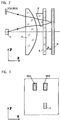
- a length measuring device 1 shown in FIG. 1 essentially consists of a light metal housing 2 in which a graduation carrier M is fastened in a known manner.
- the housing 2 is shown partially in section, so that a scanning device 4 is visible.
- the scanning device 4 also scans a measuring graduation 3a, which is applied to the graduation carrier M, in a likewise known manner.
- a reference mark 3b is assigned to a specific location.
- the driver 5 extends through a longitudinal slot 2a in the housing 2, which is sealed by roof-shaped sealing lips 7 and 8.
- a machine not shown, in which the displacements between the machine bed and the slide are to be measured, carries the scanning device 4 on the machine bed via the mounting foot 6 and driver 5 and the housing 2 with the graduation carrier M on the slide.
- the beam path for scanning the incremental track is no longer shown and described in the following considerations. However, it is preferably carried out using the same light source and collimator lens.
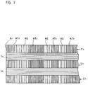
- the light from a light source L is collimated by a lens K and deflected by a prism P perpendicular to the measuring direction X (in the Y direction). It encounters a scanning plate A, which according to FIG. 4 consists of several tracks S, S ', which are arranged periodically alternately perpendicular to the measuring direction X. While the tracks S are transparent, the structured tracks S 'contain transparent areas AT between the division marks AG, which are designed as longitudinal gratings AG and which are arranged along the measuring direction X similar to the columns of a conventional reference mark.
- the longitudinal gratings AG are designed as phase gratings, the webs of which run perpendicular to the measuring direction X and which are designed such that their 0th diffraction order is suppressed.
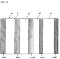
- the beam of rays passing through the scanning plate A strikes the reflection scale M with an arrangement of reflective graduation marks MR and absorbing (or scattering) areas MA.
- the distribution of the transparent areas AT of the scanning plate A corresponds to the arrangement of the absorbing areas MA of the reference mark structure 3b of the scale M (FIG. 5).
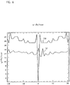
- the arrangement or distribution of the reflective graduation markings MR and the transparent areas AT is selected in a known manner such that a scanning signal S0 (FIG. 6) with an extremum is generated only in a zero position.
- the beam of rays reflected by the scale M passes through the scanning plate A and the prism P a second time and is directed by the lens K onto two photo elements PD0 and PD1 (see FIG. 3).
- PD0 detects the partial beam which is deflected only perpendicular to the measuring direction by the two prism deflections.
- the partial beam bundle, which is captured by PD1 is also also diffracted by the longitudinal gratings AG in the measuring direction X in the first order of diffraction.
- the zero position of the reference mark 3b is considered, at which the identical arrangements of the absorbing areas MA of the scale M and the transparent areas AT of the scanning plate A face each other.
- the light beam which falls through the transparent tracks S, illuminates the scale M uniformly in the measuring direction X and is reflected by the graduation marks MR. Since the beam of light is inclined perpendicular to the measuring direction due to the action of the prism P, it no longer strikes the transparent track S on the second pass through the scanning plate A, but rather the structured track S '. The track widths of S and S 'are chosen accordingly.
- the light beam reflected by the graduation marks MR then arrives at the longitudinal grating AG and is deflected in the first (longitudinal) diffraction order. The light beam therefore falls on the photo element PD1, which delivers a high clock signal S1 in the zero position. In this position, PD0 generates a particularly low push-pull signal S0.
- the light beam bundle which falls on the structured tracks S 'during the first pass through the scanning plate A and the transparent tracks S during the second pass, provides similar signal components: the partial beam bundle striking the transparent areas AT during the first pass is detected by the areas MA of the M scale absorbed. Only the partial beam bundle, which is initially deflected by the longitudinal grating AG in the first (longitudinal) diffraction order, at least partially strikes the reflective graduation marks MR of the scale M and is finally directed onto the photo element PD1 via the transparent track S. The signal level S1 of this photo element PD1 is on this way further increased while the photo element PD0 continues to have a low signal level S0.
- the prism P for generating the transverse offset of the light beams on the outward and return path is particularly advantageous since it causes a defined offset without scattered light.
- the inclination of the prism angle is selected such that a light beam that falls through one of the tracks S on the way LKPAM passes transversely offset through one of the other tracks S ′ on the way back MAPK-PD, and that a light beam that passes through one of the tracks when going there S 'falls, on the way back transversely offset by one of the other tracks S falls.
- the nominal distance N between the scanning plate A and the scale M is dimensioned such that the light beams from the outward and return path meet the scanning plate A at a distance of R at a predetermined prism angle.
- the transparent tracks S are wider (in the Y direction) than the tracks S '. This is particularly advantageous in order to ensure that when the distance N changes, the tracks S 'on S and S on S' are mapped without modulation taking place. Even when the distance N changes, S 'is completely mapped to S without any shadowing at the edges.
- the relatively weakly modulated clock signal S1 is used to generate a reference level for the strongly modulated push-pull signal S0 from the same division field on the M scale (single-field sampling). Single-field scans of this type are particularly insensitive to contamination, since both signals are equally impaired when contaminated.
- Clock signal S1 and push-pull signal S0 are connected in a known manner in a difference in order to obtain a reference pulse from the intersections of the two signals S1 and S0.
- the reference pulse width can be set by different amplification of the two signals S0, S1.
Landscapes
- Physics & Mathematics (AREA)
- General Physics & Mathematics (AREA)
- Length Measuring Devices By Optical Means (AREA)
- Optical Transform (AREA)
- Length Measuring Devices With Unspecified Measuring Means (AREA)
- Vehicle Body Suspensions (AREA)
- Body Structure For Vehicles (AREA)
- Analysing Materials By The Use Of Radiation (AREA)
Applications Claiming Priority (2)
| Application Number | Priority Date | Filing Date | Title |
|---|---|---|---|
| DE19525874A DE19525874A1 (de) | 1995-07-15 | 1995-07-15 | Positionsmeßvorrichtung |
| DE19525874 | 1995-07-15 |
Publications (3)
| Publication Number | Publication Date |
|---|---|
| EP0754933A2 true EP0754933A2 (fr) | 1997-01-22 |
| EP0754933A3 EP0754933A3 (fr) | 1998-07-08 |
| EP0754933B1 EP0754933B1 (fr) | 2001-12-05 |
Family
ID=7766943
Family Applications (1)
| Application Number | Title | Priority Date | Filing Date |
|---|---|---|---|
| EP96109635A Expired - Lifetime EP0754933B1 (fr) | 1995-07-15 | 1996-06-15 | Dispositif de mesure de positions |
Country Status (5)
| Country | Link |
|---|---|
| US (1) | US5739911A (fr) |
| EP (1) | EP0754933B1 (fr) |
| JP (1) | JP3717238B2 (fr) |
| AT (1) | ATE210280T1 (fr) |
| DE (2) | DE19525874A1 (fr) |
Cited By (3)
| Publication number | Priority date | Publication date | Assignee | Title |
|---|---|---|---|---|
| US6198534B1 (en) | 1997-08-07 | 2001-03-06 | Johannes Heidenhain Gmbh | Scanning unit for an optical position measuring system |
| US7271920B2 (en) | 2003-09-23 | 2007-09-18 | Dr. Johannes Heidenhain Gmbh | Position-measuring device |
| US7297935B2 (en) | 2004-07-16 | 2007-11-20 | Dr. Johnannes Heidenhain Gmbh | Position-measuring device |
Families Citing this family (8)
| Publication number | Priority date | Publication date | Assignee | Title |
|---|---|---|---|---|
| DE19962278A1 (de) * | 1999-12-23 | 2001-08-02 | Heidenhain Gmbh Dr Johannes | Positionsmeßeinrichtung |
| TW552645B (en) * | 2001-08-03 | 2003-09-11 | Semiconductor Energy Lab | Laser irradiating device, laser irradiating method and manufacturing method of semiconductor device |
| DE10329374A1 (de) * | 2003-06-30 | 2005-01-20 | Dr. Johannes Heidenhain Gmbh | Abtastbaueinheit einer Positionsmesseinrichtung |
| US7191943B2 (en) * | 2004-07-28 | 2007-03-20 | Caterpillar Inc | Robust barcode and reader for rod position determination |
| DE102006005574B4 (de) | 2006-02-06 | 2010-05-20 | Johann Wolfgang Goethe-Universität Frankfurt am Main | Meßvorrichtung zur Bestimmung der Größe, Größenverteilung und Menge von Partikeln im nanoskopischen Bereich |
| US7965393B2 (en) | 2007-07-24 | 2011-06-21 | Mitutoyo Corporation | Reference signal generating configuration for an interferometric miniature grating encoder readhead using fiber optic receiver channels |
| US20090027692A1 (en) * | 2007-07-24 | 2009-01-29 | Mitutoyo Corporation | Reference signal generating configuration for an interferometric miniature grating encoder readhead using fiber optic receiver channels |
| US7973941B2 (en) * | 2007-07-24 | 2011-07-05 | Mitutoyo Corporation | Reference signal generating configuration for an interferometric miniature grating encoder readhead using fiber optic receiver channels |
Family Cites Families (3)
| Publication number | Priority date | Publication date | Assignee | Title |
|---|---|---|---|---|
| GB8320629D0 (en) * | 1983-07-30 | 1983-09-01 | Pa Consulting Services | Displacement measuring apparatus |
| DE3416864C2 (de) * | 1984-05-08 | 1986-04-10 | Dr. Johannes Heidenhain Gmbh, 8225 Traunreut | Photoelektrische Meßeinrichtung |
| DE3834676A1 (de) * | 1988-10-12 | 1990-04-19 | Heidenhain Gmbh Dr Johannes | Photoelektrische positionsmesseinrichtung |
-
1995
- 1995-07-15 DE DE19525874A patent/DE19525874A1/de not_active Withdrawn
-
1996
- 1996-06-15 DE DE59608345T patent/DE59608345D1/de not_active Expired - Lifetime
- 1996-06-15 AT AT96109635T patent/ATE210280T1/de not_active IP Right Cessation
- 1996-06-15 EP EP96109635A patent/EP0754933B1/fr not_active Expired - Lifetime
- 1996-07-12 JP JP18376796A patent/JP3717238B2/ja not_active Expired - Fee Related
- 1996-07-12 US US08/679,201 patent/US5739911A/en not_active Expired - Lifetime
Cited By (4)
| Publication number | Priority date | Publication date | Assignee | Title |
|---|---|---|---|---|
| US6198534B1 (en) | 1997-08-07 | 2001-03-06 | Johannes Heidenhain Gmbh | Scanning unit for an optical position measuring system |
| US7271920B2 (en) | 2003-09-23 | 2007-09-18 | Dr. Johannes Heidenhain Gmbh | Position-measuring device |
| CN100401020C (zh) * | 2003-09-23 | 2008-07-09 | 约翰尼斯海登海恩博士股份有限公司 | 位置测量装置 |
| US7297935B2 (en) | 2004-07-16 | 2007-11-20 | Dr. Johnannes Heidenhain Gmbh | Position-measuring device |
Also Published As
| Publication number | Publication date |
|---|---|
| US5739911A (en) | 1998-04-14 |
| DE59608345D1 (de) | 2002-01-17 |
| JP3717238B2 (ja) | 2005-11-16 |
| EP0754933B1 (fr) | 2001-12-05 |
| JPH0933212A (ja) | 1997-02-07 |
| DE19525874A1 (de) | 1997-01-16 |
| EP0754933A3 (fr) | 1998-07-08 |
| ATE210280T1 (de) | 2001-12-15 |
Similar Documents
| Publication | Publication Date | Title |
|---|---|---|
| EP1923673B1 (fr) | Dispositif de mesure de position | |
| EP0509979B1 (fr) | Dispositif de mesure de positions photo-électronique | |
| EP0896206B1 (fr) | Unité de lecture pour dispositif optique de mesure de position | |
| EP0160811B1 (fr) | Dispositif de mesure photo-électrique | |
| EP1081457B1 (fr) | Dispositif optique de mesure de la position | |
| DE3541199C1 (de) | Lichtelektrische Positionsmesseinrichtung | |
| DE102008007319A1 (de) | Optische Positionsmesseinrichtung | |
| DE3905730C2 (de) | Positionsmeßeinrichtung | |
| EP0669518B1 (fr) | Dispositif pour générer des signaux dépendants de la position | |
| DE10058239B4 (de) | Positionsmeßeinrichtung | |
| EP0754933B1 (fr) | Dispositif de mesure de positions | |
| DE69527498T2 (de) | Optischer Sensor | |
| AT404637B (de) | Photoelektrische positionsmesseinrichtung | |
| EP1028309B1 (fr) | Codeur optique | |
| EP0747674B1 (fr) | Dispositif photo-électrique de mesure de positions | |
| EP1085291B1 (fr) | Dispsitif pour la détermination de positions et de défaults de translation | |
| DE10020575A1 (de) | Abtasteinheit für eine optische Positionsmesseinrichtung | |
| EP3936830B1 (fr) | Dispositif optique de mesure de la position | |
| EP0626564B1 (fr) | Dispositif de mesure d'angles ou de longueur | |
| DE10346380B4 (de) | Positionsmesseinrichtung | |
| DE3939504C2 (fr) | ||
| DE19957777A1 (de) | Optische Positionsmeßeinrichtung | |
| DE9011628U1 (de) | Optoelektronische Anordnung zum Abtasten von Codeträgern | |
| DE9218275U1 (de) | Lichtelektrische Längen- oder Winkelmeßeinrichtung | |
| DE8916216U1 (de) | Positionsmeßeinrichtung |
Legal Events
| Date | Code | Title | Description |
|---|---|---|---|
| PUAI | Public reference made under article 153(3) epc to a published international application that has entered the european phase |
Free format text: ORIGINAL CODE: 0009012 |
|
| AK | Designated contracting states |
Kind code of ref document: A2 Designated state(s): AT CH DE FR GB IT LI |
|
| PUAL | Search report despatched |
Free format text: ORIGINAL CODE: 0009013 |
|
| AK | Designated contracting states |
Kind code of ref document: A3 Designated state(s): AT CH DE FR GB IT LI |
|
| 17P | Request for examination filed |
Effective date: 19990108 |
|
| GRAG | Despatch of communication of intention to grant |
Free format text: ORIGINAL CODE: EPIDOS AGRA |
|
| GRAG | Despatch of communication of intention to grant |
Free format text: ORIGINAL CODE: EPIDOS AGRA |
|
| GRAH | Despatch of communication of intention to grant a patent |
Free format text: ORIGINAL CODE: EPIDOS IGRA |
|
| RIC1 | Information provided on ipc code assigned before grant |
Free format text: 7G 01D 5/36 A |
|
| GRAH | Despatch of communication of intention to grant a patent |
Free format text: ORIGINAL CODE: EPIDOS IGRA |
|
| 17Q | First examination report despatched |
Effective date: 20010516 |
|
| ITF | It: translation for a ep patent filed | ||
| GRAA | (expected) grant |
Free format text: ORIGINAL CODE: 0009210 |
|
| AK | Designated contracting states |
Kind code of ref document: B1 Designated state(s): AT CH DE FR GB IT LI |
|
| REF | Corresponds to: |
Ref document number: 210280 Country of ref document: AT Date of ref document: 20011215 Kind code of ref document: T |
|
| REG | Reference to a national code |
Ref country code: CH Ref legal event code: NV Representative=s name: TROESCH SCHEIDEGGER WERNER AG Ref country code: CH Ref legal event code: EP |
|
| REG | Reference to a national code |
Ref country code: GB Ref legal event code: IF02 |
|
| REF | Corresponds to: |
Ref document number: 59608345 Country of ref document: DE Date of ref document: 20020117 |
|
| GBT | Gb: translation of ep patent filed (gb section 77(6)(a)/1977) |
Effective date: 20020129 |
|
| ET | Fr: translation filed | ||
| PLBE | No opposition filed within time limit |
Free format text: ORIGINAL CODE: 0009261 |
|
| STAA | Information on the status of an ep patent application or granted ep patent |
Free format text: STATUS: NO OPPOSITION FILED WITHIN TIME LIMIT |
|
| 26N | No opposition filed | ||
| PGFP | Annual fee paid to national office [announced via postgrant information from national office to epo] |
Ref country code: AT Payment date: 20070618 Year of fee payment: 12 |
|
| PGFP | Annual fee paid to national office [announced via postgrant information from national office to epo] |
Ref country code: IT Payment date: 20080625 Year of fee payment: 13 |
|
| PGFP | Annual fee paid to national office [announced via postgrant information from national office to epo] |
Ref country code: FR Payment date: 20080613 Year of fee payment: 13 |
|
| PG25 | Lapsed in a contracting state [announced via postgrant information from national office to epo] |
Ref country code: AT Free format text: LAPSE BECAUSE OF NON-PAYMENT OF DUE FEES Effective date: 20080615 |
|
| REG | Reference to a national code |
Ref country code: FR Ref legal event code: ST Effective date: 20100226 |
|
| PG25 | Lapsed in a contracting state [announced via postgrant information from national office to epo] |
Ref country code: FR Free format text: LAPSE BECAUSE OF NON-PAYMENT OF DUE FEES Effective date: 20090630 |
|
| PGFP | Annual fee paid to national office [announced via postgrant information from national office to epo] |
Ref country code: CH Payment date: 20100623 Year of fee payment: 15 |
|
| PG25 | Lapsed in a contracting state [announced via postgrant information from national office to epo] |
Ref country code: IT Free format text: LAPSE BECAUSE OF NON-PAYMENT OF DUE FEES Effective date: 20090615 |
|
| REG | Reference to a national code |
Ref country code: CH Ref legal event code: PL |
|
| PG25 | Lapsed in a contracting state [announced via postgrant information from national office to epo] |
Ref country code: LI Free format text: LAPSE BECAUSE OF NON-PAYMENT OF DUE FEES Effective date: 20110630 Ref country code: CH Free format text: LAPSE BECAUSE OF NON-PAYMENT OF DUE FEES Effective date: 20110630 |
|
| PGFP | Annual fee paid to national office [announced via postgrant information from national office to epo] |
Ref country code: GB Payment date: 20120622 Year of fee payment: 17 |
|
| PGFP | Annual fee paid to national office [announced via postgrant information from national office to epo] |
Ref country code: DE Payment date: 20130620 Year of fee payment: 18 |
|
| GBPC | Gb: european patent ceased through non-payment of renewal fee |
Effective date: 20130615 |
|
| PG25 | Lapsed in a contracting state [announced via postgrant information from national office to epo] |
Ref country code: GB Free format text: LAPSE BECAUSE OF NON-PAYMENT OF DUE FEES Effective date: 20130615 |
|
| REG | Reference to a national code |
Ref country code: DE Ref legal event code: R119 Ref document number: 59608345 Country of ref document: DE |
|
| REG | Reference to a national code |
Ref country code: DE Ref legal event code: R119 Ref document number: 59608345 Country of ref document: DE Effective date: 20150101 |
|
| PG25 | Lapsed in a contracting state [announced via postgrant information from national office to epo] |
Ref country code: DE Free format text: LAPSE BECAUSE OF NON-PAYMENT OF DUE FEES Effective date: 20150101 |