EP0754980A2 - Bildbehandlungsgerät und -verfahren - Google Patents
Bildbehandlungsgerät und -verfahren Download PDFInfo
- Publication number
- EP0754980A2 EP0754980A2 EP96305336A EP96305336A EP0754980A2 EP 0754980 A2 EP0754980 A2 EP 0754980A2 EP 96305336 A EP96305336 A EP 96305336A EP 96305336 A EP96305336 A EP 96305336A EP 0754980 A2 EP0754980 A2 EP 0754980A2
- Authority
- EP
- European Patent Office
- Prior art keywords
- image
- density
- data
- image forming
- forming units
- Prior art date
- Legal status (The legal status is an assumption and is not a legal conclusion. Google has not performed a legal analysis and makes no representation as to the accuracy of the status listed.)
- Withdrawn
Links
Images









Classifications
-
- G—PHYSICS
- G03—PHOTOGRAPHY; CINEMATOGRAPHY; ANALOGOUS TECHNIQUES USING WAVES OTHER THAN OPTICAL WAVES; ELECTROGRAPHY; HOLOGRAPHY
- G03G—ELECTROGRAPHY; ELECTROPHOTOGRAPHY; MAGNETOGRAPHY
- G03G15/00—Apparatus for electrographic processes using a charge pattern
- G03G15/01—Apparatus for electrographic processes using a charge pattern for producing multicoloured copies
-
- G—PHYSICS
- G03—PHOTOGRAPHY; CINEMATOGRAPHY; ANALOGOUS TECHNIQUES USING WAVES OTHER THAN OPTICAL WAVES; ELECTROGRAPHY; HOLOGRAPHY
- G03G—ELECTROGRAPHY; ELECTROPHOTOGRAPHY; MAGNETOGRAPHY
- G03G15/00—Apparatus for electrographic processes using a charge pattern
- G03G15/50—Machine control of apparatus for electrographic processes using a charge pattern, e.g. regulating differents parts of the machine, multimode copiers, microprocessor control
- G03G15/5033—Machine control of apparatus for electrographic processes using a charge pattern, e.g. regulating differents parts of the machine, multimode copiers, microprocessor control by measuring the photoconductor characteristics, e.g. temperature, or the characteristics of an image on the photoconductor
- G03G15/5041—Detecting a toner image, e.g. density, toner coverage, using a test patch
-
- G—PHYSICS
- G03—PHOTOGRAPHY; CINEMATOGRAPHY; ANALOGOUS TECHNIQUES USING WAVES OTHER THAN OPTICAL WAVES; ELECTROGRAPHY; HOLOGRAPHY
- G03G—ELECTROGRAPHY; ELECTROPHOTOGRAPHY; MAGNETOGRAPHY
- G03G2215/00—Apparatus for electrophotographic processes
- G03G2215/01—Apparatus for electrophotographic processes for producing multicoloured copies
- G03G2215/0103—Plural electrographic recording members
Definitions
- This invention relates to an image processing apparatus and method and, more particularly, to an image processing apparatus and method for performing image formation using a plurality of image forming units.
- a plurality of color toner images are formed on an image carrier in an image forming unit, and are sequentially transferred onto a recording medium to overlap each other, thereby forming a full-color image. Therefore, in order to stabilize the image quality of an output image, the toner images to be transferred to overlap each other must always maintain a stable density balance.
- an image carrier such as a photosensitive body or photoconductor
- light emitted by a predetermined LED and reflected by each of the specific patterns in units of colors is measured by a sensor such as a photodiode, thus detecting the toner densities of the respective colors.
- the measurement result is fed back to an image forming condition, e.g., ⁇ correction, thereby improving stability of the final output image quality.
- a specific pattern is formed on the image carrier in correspondence with the environmental variation amount, and the density of the specific pattern is read in the same manner as the above-mentioned method.
- the measurement result is fed back to an image forming condition, e.g., ⁇ correction, thus improving stability of the final output image quality as well.
- an image forming apparatus having a plurality of image carriers for respectively forming a plurality of color toner images does not give a sufficient consideration to precise detection of the states of the image carriers and feeding back of the detection results to correction control of image data.
- controlling the image forming condition of such image forming apparatus by effectively using an image reading means for supplying image data is not given a sufficient consideration, either.
- toner image reading means for reading light reflected by toner images of specific patterns on the respective image carriers must be substantially absolutely equivalent to each other with respect to the respective colors.
- the "absolutely equivalent” state is a state wherein the toner image reading means for respectively reading light reflected by, e.g., yellow, magenta, and cyan toner images used in image formation detect equal density values when they read a gray scale in achromatic color formed by evenly superposing the three colors.
- the toner image reading means It is possible to some extent to adjust the toner image reading means to be absolutely equivalent to each other for the respective colors upon assembling of the image forming apparatus.
- the toner image reading means for a certain color is exchanged due to, e.g., a failure, it is very difficult to adjust the characteristics of the exchanged toner image reading means to be absolutely equivalent to those of other toner image reading means.
- the density obtained by reading a specific pattern on each image carrier does not always match the density of an image actually output onto a recording medium (paper) after the image forming units have been used over a long period of time.
- the surface of the image carrier is roughened, and the relationship between the adhesion amount of toner and the reflected light amount changes from that in an initial state.
- Such change also takes place when the optical characteristics of the toner image reading means change due to, e.g., adhesion of toner, dust, and the like to an optical window for protecting an optical element.
- an image forming apparatus having a plurality of image forming units must have a means for strictly correcting the characteristics of the toner image reading means themselves, and their relationship.
- the image forming apparatus does not have any correction means, an output image with an optimal color balance cannot be obtained when the toner image reading means is exchanged or when the apparatus is used over a long period of time.
- an image forming apparatus which has one image carrier and a transfer drum, and sequentially transfers and outputs respective color toner images formed in turn on the image carrier onto a recording medium carried on the transfer drum will be examined.
- Such image forming apparatus has only one toner image reading means, and hence, the respective colors are read by a single sensor within a predetermined photosensitivity range. For this reason, it is checked whether a certain relative density ratio is obtained among the densities of the colors even when, for example, the sensitivity of this sensor deviates from average sensitivity.
- the constituting elements such as photodiodes that constitute toner image reading means in the respective image forming units have a difference although the difference falls within a tolerance.
- the image forming units of the respective colors have different maximum toner density values in (1), and hence, it is difficult to form an achromatic gray scale.
- the fogging amount control in (3) is not sufficient, and for example, chromatic fog may be generated upon formation of a gray scale image.
- an image processing apparatus and method which can maintain image formation with a good color balance and gradation characteristics over an extended period of time, i.e., to accurately detect the states of color image forming units, and to control gradation correction on the basis of the detected states.
- an image processing apparatus comprising pattern forming means for forming pattern images by outputting specific pattern data to the image forming units; first density measuring means, arranged in correspondence with the image forming units, for measuring densities of the pattern images formed by the image forming units to obtain first density data; gradation correcting means for performing gradation correction of image data to be output to the image forming units; and control means for controlling correction characteristics of said gradation correction means in accordance with the first density data.
- Another concern of the present invention is to provide an image processing apparatus and method, which control the gradation characteristics on the basis of a pattern density obtained by outputting pattern images formed on image forming units onto a medium to overlap each other.
- an image processing apparatus further comprising second density measuring means for obtaining second density data for a plurality of colors on the basis of image signals obtained by reading, by said image input means, a recording medium on which a plurality of color pattern images are formed, and wherein said control means controls the correction characteristics of said gradation correction means in accordance with the first and second density data.
- a further concern of the present invention is to provide an image processing apparatus and method, which can control the gradation correction characteristics on the basis of a pattern image density obtained by actually outputting the densities of pattern images formed on image forming units onto a medium to overlap each other by effectively using an image readinq means.
- the present invention provides an image processing apparatus having a plurality of image forming units for performing image formation using predetermined colors, comprising reading means for reading an original image, and generating color image data; color component output means for outputting a plurality of color component data corresponding to each of the image forming units on the basis of the color image data; correction means for correcting gradation characteristics of the plurality of color component data; output means for outputting a medium on which a color image is formed by the plurality of image forming units; supply means for supplying a reference pattern signal to the plurality of image forming units; and control means for controlling gradation correction characteristics of said correction means on the basis of color image data generated by said reading means which reads a medium on which a reference color signal is formed by the image forming units on the basis of the reference pattern signal.
- an image processing apparatus having a plurality of image forming units for performing image formation using predetermined colors, wherein each of the image forming units comprises an image carrier for carrying an image, and conversion means for reading the image on said image carrier and converting the read image into an electrical signal, and said apparatus further comprises correction means for correcting a variation of said conversion means of the image forming units.
- the invention is particularly advantageous since an image with good gradation characteristics and color balance can be formed over a long period of time upon formation of a full-color image.
- Fig. 1 is a sectional view of a printer 100 as an image forming apparatus of this embodiment, which has a plurality of image forming units.
- the printer 100 comprises a laser beam printer (LBP), and forms an image on a recording medium on the basis of an image signal of an original read by an original reading unit 202.
- Reference numeral 300 denotes an operation panel on which various switches for operations, LED indicators, and the like are arranged; and 201, a printer control unit for controlling the entire printer 100, and interpreting character information and the like supplied from a host computer (not shown) or the like.
- the printer control unit 201 performs gradation correction processing of this embodiment, and converts an image signal into a driving signal of a semiconductor laser 103 and outputs it to a laser driver 102.
- the laser driver 102 is a circuit for driving the semiconductor laser 103.
- the laser driver 102 switches the ON/OFF state of the semiconductor laser 103 in correspondence with an input original image signal, and controls the laser ON time.
- Four sets of laser drivers 102 and semiconductor lasers 103 are arranged in correspondence with Y, M, C, and K colors.
- Reference numerals 1a, 1b, 1c, and 1d denote photosensitive drums for forming yellow (Y), magenta (M), cyan (C), and black (K) toner images; 2a, 2b, 2c, and 2d, developers for developing the corresponding toner images; 3a, 3b, 3c, and 3d, toner image density measuring units for measuring the toner densities on the corresponding photosensitive drums in this embodiment; and 4a, 4b, 4c, and 4d, cleaning blades for removing residual toner which is not transferred onto a recording medium.
- a group of, for example, the components la, 2a, 3a, and 4a is called one image forming unit. More specifically, the printer 100 comprises four image forming units.
- Laser beams emitted by the semiconductor lasers 103 are deflected in the right-and-left directions by rotary polygonal mirrors 11, and scan the surfaces of the photosensitive drums 1a to 1d via a plurality of mirrors, thus forming electrostatic latent images in units of colors.
- the photosensitive drums 1a to 1d on which the latent images are formed rotate in the direction of an arrow, and the latent images are visualized as toner images by the corresponding developers 2a to 2d.
- a recording medium 6 such as a recording sheet stored in one of recording sheet cassettes 61 is placed on a transfer belt 31, and the toner images formed on the photosensitive drums la to ld in the order of Y, M, C, and K are transferred onto the recording medium 6. Then, the recording medium 6 is conveyed by a conveyor belt 62. When a double-sided copy operation is to be performed, the recording medium is reversed by the conveyor belt 62 by moving a separation plate 64 downward in Fig. 1, and the reversed recording medium is conveyed onto the transfer belt 31 again.
- the recording medium 6 Upon completion of the transfer operation, the recording medium 6 is separated from the transfer belt 31, and the toner images are fixed by a pair of fixing rollers 51 and 52 in a fixing unit 5. Thereafter, the recording medium 6 is exhausted onto a sheet exhaust unit 63. As described above, a full-color image is formed on the recording medium 6 in the printer 100.
- Fig. 2 is a block diagram for explaining in detail the toner image density measuring unit 3a in the yellow image forming unit shown in Fig. 1 above.
- the toner density measuring unit 3a comprises an LED 8a, a photosensor 9a, a D/A converter 10a, and an A/D converter 11a.
- a predetermined digital signal value is input to the D/A converter 10a and is converted into an analog signal value.
- the LED 8a illuminates a toner image formed on the photosensitive drum 1a.
- Light reflected by the yellow toner image is detected by the photosensor 9a as an analog signal indicating the luminance level.
- the detected analog signal is converted by the A/D converter 11a into a digital signal.
- the yellow toner density is measured on the basis of the signal detected by the photosensor 9a.
- the remaining toner image density measuring units 3b to 3d shown in Fig. 1 have the same arrangement as that of the toner image density measuring unit 3a shown in Fig. 2. Note that the outputs of the LEDs 8a to 8d and the peak values of optical wavelengths to be detected by the photosensors 9a to 9d are respectively set to be optimal values in advance in correspondence with the individual toner colors in the toner image density measuring units 3a to 3d.
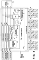
- Fig. 3 is a block diagram showing the arrangement of the printer control unit 201.
- reference numeral 43 denotes a CPU which comprises a microprocessor, and the like, and executes a control program (to be described later).
- Reference numeral 210 denotes a ROM for storing a control program of the CPU 43 and various data; 212, a RAM used as a work area of the CPU 43; 42, a luminance-density conversion unit for performing luminance-density conversion (to be described later); 213, an I/O control unit for exchanging data between the above-mentioned toner image density measuring units 3a to 3d and the CPU 43; and 291 to 294, ⁇ correction units for respectively performing ⁇ correction processing for Y, M, C, and K.
- Each of the ⁇ correction units 291 to 294 comprises a ⁇ -LUT 44 for correcting the density characteristics of input image data, a pattern generator 45 for generating a pattern signal representing a patch pattern, a selector 46 for selecting one of the outputs from the ⁇ -LUT 44 and the pattern generator 45 in accordance with an instruction from the CPU 43, and a pulse width modulation unit 47 for performing pulse width modulation of the output from the selector 46 on the basis of comparison with a triangular wave having a predetermined period.
- the ⁇ -LUT 44 comprises a RAM, and its correction characteristics are set by the CPU 43.
- the pattern generator 45 generates a pattern signal so as to form a patch pattern (to be described later) in synchronism with an ITOP signal that indicates the write start timing of the leading end of an image.
- the selector 46 selects the A side (the pattern signal from the pattern generator 45) when the CPU 43 sets a mode for performing gradation characteristic stabilization control (to be described later), or selects the B side (the correction signal from the ⁇ -LUT 44) when the CPU 43 sets a normal mode for actually reproducing an original image.
- Reference numerals 1021 to 1024 denote laser drivers for driving lasers so as to form Y, M, C, and K images, respectively.
- image signals of an original image read by the CCD sensor of the original reading unit 202 are subjected to gradation correction in the ⁇ correction units 291 to 294, as will be described later, and the corrected image signals are used for forming images on a recording sheet. Thereafter, the recording sheet on which a full-color image is formed is output from the printer unit 100.
- a luminance signal of light reflected by a yellow toner image detected by the photosensor 9a in the toner image density measuring unit 3a is input to the luminance-density conversion unit 43 via the I/O control unit 213 in the printer control unit 201, and is converted into a density signal.
- the density signal is then supplied to the CPU 43.
- the CPU 43 sets a density correction parameter (to be described later) for yellow on the basis of the signal supplied from the photosensor 9a.
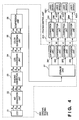
- Fig. 4 shows the detailed arrangement of an original reading unit 202 of this embodiment.
- the original reading unit 202 comprises a CCD line sensor 21, an A/D conversion unit 22, a shading correction unit 23, a LOG conversion unit 24, a color conversion unit 25, a compression unit 26, a storage unit 27, and expansion units 281 to 284.
- R, G, and B luminance signals of an original image read by the CCD 21 in the original reading unit 202 are input to the A/D conversion unit 22, and are converted into R, G, and B digital luminance signals. These digital luminance signals are supplied to the shading correction unit 23, and are subjected to shading correction to eliminate sensitivity variations and light amount unevenness of the individual elements of the CCD 21.
- the R, G, and B luminance signals corrected by the shading correction unit 23 are LOG-converted into C, M, and Y signals by the LOG conversion unit 24.
- the C, M, and Y image signals output from the LOG conversion unit 24 are converted into L*, a*, and b* luminance chromaticity signals by the color conversion unit 25, and the converted signals are compressed by the compression unit 26 in units of two-dimensional blocks having a predetermined size using a multi-valued image data encoding method such as vector quantization.
- the compressed data for one scan of the CCD 21 are stored in the storage unit 27.
- the expansion units 281 to 284 Upon forming an image, the expansion units 281 to 284 read out the L*, a*, and b* compressed data stored in the storage unit 27, convert them into Y, M, C, and K recording color component signals, and supply the converted signals to the printer control unit 201. At this time, in the printer of this embodiment, since the toner image transfer positions of the Y, M, C, and K photosensitive drums 1a to 1d are offset from each other, the expansion units 281 to 284 can parallelly supply image data at spatially different positions to the printer control unit 201.
- the Y, M, C, and K signals expanded by the expansion units 281 to 284 are supplied to the ⁇ correction units 291 to 294, and their characteristics are set using the corresponding ⁇ -LUTs 44, as will be described later. Then, the image signals are converted, so that the original image densities match the output image densities processed according to the ⁇ characteristics upon initializing the printer unit 100 (in the stabilization control mode).
- the image signals input to the ⁇ correction units 291 to 294 are converted into pulse-width modulated signals by the pulse width modulation unit 47, and the converted signals are input to the laser drivers 1021 to 1024, thus driving the semiconductor lasers 103 shown in Fig. 1.
- electrostatic latent images having gradation characteristics defined by changes in dot area are formed on the photosensitive drums la to 1d by scanning laser beams using a gradation reproduction means based on pulse-width conversion processing in which pixels of all the colors are arranged in the sub-scanning direction, and gradation images are obtained via the developing, transfer, and fixing processes.
- Fig. 5 shows the characteristics for density reproduction of an original image.
- the first quadrant (the upper right region in Fig. 5) represents the characteristics of the original reading unit 202 for converting an original density into a density signal
- the second quadrant (the lower right region in Fig. 5) represents the characteristics of the ⁇ -LUT 44 for converting the density signal into a laser output signal.
- the third quadrant (the lower left region in Fig. 5) represents the characteristics of the printer unit 100 for converting the laser output signal into a printer output density
- the fourth quadrant (the upper left region in Fig. 5) represents the relationship between the original density and the printer output density. That is, the characteristics shown in the fourth quadrant represent the gradation characteristics of the printer unit 100 of this embodiment as a whole.
- the distortion of the printer characteristics shown in the third quadrant is corrected by the ⁇ -LUT 44 having the characteristics shown in the second quadrant, so as to obtain linear gradation characteristics in the printer unit 100, as shown in the fourth quadrant in Fig. 5.
- each image signal is processed as an 8-bit digital signal in this embodiment.
- Fig. 6 is a diagram for explaining the state wherein a signal output from the photosensor 9a corresponding to light reflected by a yellow toner image is input to the CPU 43.
- reference numeral 42 denotes a luminance-density conversion unit, which has luminance-density conversion tables (to be simply referred to as conversion tables hereinafter) 42a to 42d.
- the conversion tables 42a to 42d comprise RAMs, and store tables, formed by the CPU 43, for respectively converting yellow, magenta, cyan, and black luminance signals into density signals in correspondence with the characteristics of the respective color components.
- Near infrared light i.e., light reflected by a yellow toner and incident on the photosensor 9a is converted by the photosensor 9a into an electrical signal, and the electrical signal, i.e., an output voltage of "0" to "5" V, is converted by the A/D converter lla into a digital signal of one of "0" to "255" levels.
- the digital luminance signal is converted into a density signal using the conversion table 42a in the luminance-density conversion unit 42, and the density signal is input to the CPU 43.
- This density data will be referred to as "first density data (Dn1)" hereinafter.
- Figs. 7 to 9 show the spectral characteristics of yellow, magenta, and cyan toners.
- the respective toners have a near infrared light (960 nm) reflectance of 80% or higher.
- a two-component developing method advantageous for color purity and transmittance is adopted.
- yellow, magenta, and cyan color toners used in this embodiment are formed by dispersing the respective coloring agents using a styrene-based polymeric resin as a binder.
- black toner uses monocomponent magnetic toner, which can reduce running cost for monochrome copies.
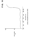
- Fig. 10 shows the spectral characteristics of black toner. As shown in Fig. 10, the near infrared light (960 nm) reflectance of black toner is as low as about 10%.
- black toner is developed by a monocomponent jumping development method. Alternatively, for example, black two-component toner may be used.
- the photosensitive drums la to ld of this embodiment comprise OPC drums, and have a near infrared light (960 nm) reflectance of about 40%.
- the photosensitive drums la to ld may comprise, e.g., amorphous silicon-based drums, or the like.
- Fig. 11 shows the relationship between the laser output signal and the outputs from the photosensors 9a to 9d when the color toner image densities on the photosensitive drums la to ld are changed stepwise by an area gradation method.
- the output from each of the photosensors 9a to 9d in a state wherein no toners adhere to the photosensitive drums la to ld is set to be "2.5" V, i.e., level "128".
- the contents of the conversion tables 42a to 42d of the luminance-density conversion unit 42 are set in accordance with Fig. 12.
- the ordinate plots the first density data (Dnl)
- the abscissa plots the outputs from the photosensors 9a to 9d.
- the yellow, magenta, cyan, and black characteristics respectively correspond to the conversion tables 42a, 42b, 42c, and 42d.
- the gradation correction control in this embodiment i.e., the setting process of each ⁇ -LUT 44 by the CPU 43, will be described below with reference to the flow chart shown in Fig. 13.
- the control program used for executing the gradation correction control of this embodiment is stored in the ROM 210, and is executed by the CPU 43 using the RAM 212 as a work area.
- a main power switch is turned “ON" in step S1. It is checked in step S2 if the temperature of the pair of fixing rollers 51 and 52, i.e., the fixing temperature is equal to or lower than 150°C. If YES in step S2, the flow advances to step S3 since it is determined that the gradation correction control must be performed; otherwise, the flow jumps to step S12 without executing any gradation correction control since it is determined that the printer unit 100 was used immediately before this processing.
- step S3 the control waits until the temperature of the fixing rollers reaches a predetermined temperature, and the laser temperature of the semiconductor lasers 103 reaches a temperature control point, so that the lasers 103 are set in a standby state.
- potential control as one mode of image stabilization control is performed. More specifically, the initial levels of the grid bias and developing bias are controlled to correct any changes in the discharge amount of a primary charger and the sensitivity deterioration of the photosensitive drums, on the basis of data obtained by measuring the potentials of the drum surfaces using potential sensors (not shown) respectively arranged in correspondence with the photosensitive drums la to ld.
- the photosensors 9a to 9d measure light reflected by the corresponding photosensitive drums to acquire data used for correcting contaminations (i.e., contaminations of so-called sensor windows) of the surfaces of the respective sensors.
- step S4 a yellow patch pattern having a maximum density value corresponding to a laser output signal "255" is formed on the corresponding photosensitive drum la.
- the pattern signal representing the patch pattern is generated by the pattern generator 45 shown in Fig. 3.
- Fig. 14 shows an example of the yellow patch pattern formed on the photosensitive drum la.
- reference numeral 130 denotes a patch pattern having a maximum density and formed on the photosensitive drum la; 8a, an LED, and 9a, a yellow photosensor.
- step S5 the LED 8a illuminates the yellow patch pattern having the maximum density formed on the photosensitive drum la in step S4, and light reflected by the patch pattern is read by the photosensor 9a.
- step S6 the read luminance signal is converted into a yellow density signal by the luminance-density conversion unit 42, as described above.
- step S7 to check the difference between the density signal obtained in step S6 and a setting maximum density value of the printer unit 100, and the contrast potential is calculated based on the difference, thereby correcting the values of the grid bias and developing bias.
- step S8 the pattern generator 45 generates a pattern signal to form a yellow multiple-gradation patch pattern on the photosensitive drum la.
- Fig. 15A shows an example of the yellow multiple-gradation patch pattern formed on the photosensitive drum la.
- the multiple-gradation patch pattern has 16 gradation levels corresponding to 16 levels, i.e., "16", "32", “48”, “64”, “80”, “96”, “112”, “128”, “144”, “160”, “176”, “192”, “208”, “224”, “240”, and “255”.
- the patch pattern shown in Fig. 15A is continuously formed in the circumferential direction of the photosensitive drum la, as shown in Fig. 15B.
- reference numeral 8a in Fig. 15B denotes an LED; and 9a, a yellow photosensor.
- step S9 the multiple-gradation patch pattern shown in Fig. 15A and 15B is illuminated by the LED 8a, and light beams reflected by the respective pattern portions are read by the photosensor 9a.
- step S10 the read luminance signals are converted into yellow density signals by the luminance-density conversion unit 42, as described above.
- the relationship between the output signal from the semiconductor laser 103 and the first density data (Dnl), i.e., the printer characteristics shown in the third quadrant in Fig. 5 above, can be accurately obtained without actually transferring, fixing, and outputting any patch pattern on a recording medium.
- step S11 the ⁇ -LUT 44 shown in Fig. 3 is calculated so as to correct the printer characteristics.
- any distortion in the recording characteristics of the printer unit shown in the third quadrant of Fig. 5 is corrected by the ⁇ -LUT 44 having the characteristics shown in the second quadrant of Fig. 5, so as to obtain linear gradation characteristics of the printer unit 100, as shown in the fourth quadrant of Fig. 5.
- step S11 by reversing the input/output relationship of the printer characteristics shown in the third quadrant of Fig. 5 obtained in step S10, the ⁇ correction characteristics of the printer unit shown in the second quadrant can be determined in units of densities, and all the contents corresponding to 256 gradation levels of the ⁇ -LUT 44 can be set.
- the above-mentioned characteristics of the ⁇ -LUT 44 are calculated and set by the CPU 43.
- steps S4 to Sll are performed for magenta, cyan, and black parallel to those for yellow, although not shown in Fig. 13.
- the patch forming operations, the patch reading operations, and the like with respect to the photosensitive drums la to ld are simultaneously performed for the respective colors.
- the CPU 43 Based on the obtained color density data, the CPU 43 sequentially calculates ⁇ -LUT data to set the ⁇ -LUTs 44 in units of colors.
- gradation characteristic stabilization control can be performed at high speed.
- step S12 Upon completion of processing for all the colors, the flow advances to step S12, and a message "ready to copy” is displayed on the operation panel 300 to inform the operator of this state. Thereafter, the printer unit is set in a copy standby state.
- the processing sequence in the gradation characteristic stabilization control mode has been described.
- the second embodiment of the present invention will be described below.
- the hardware arrangement of the second embodiment is the same as that in the first embodiment, and a detailed description thereof will be omitted.
- the densities obtained by reading patterns on the photosensitive drums la to ld often deviate from those of an actual printout image.
- the cleaning blades are in sliding contact with the photosensitive drums 1a to 1d for a long period of time so as to remove the residual toners on the photosensitive drums 1a to 1d after the transfer process, the surfaces of the photosensitive drums la to ld roughen, and hence, scattered light components increase. For this reason, the relationship between the outputs from the photosensors 9a to 9d and the formed image densities changes from an initial state.
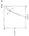
- Fig. 16 shows the relationship between the output from the photosensor 9a and the actually output image density while taking yellow as an example.
- a curve 140 in Fig. 16 represents an ideal relationship as in Fig. 12 above, but a curve 141 represents the relationship after image formation was performed on 10,000 sheets. More specifically, as the printer unit 100 is used, the output image density tends to lower.
- the second embodiment has as its object to prevent the output image density from lowering due to a long term use of the printer unit 100 by executing the second gradation correction control in addition to the first gradation correction control in the first embodiment described above.
- the second gradation correction control is performed after the above-mentioned first gradation correction control has ended.
- the second gradation correction control is characterized by performing luminance-density conversion table updating processing immediately before or after step S3 in the flow chart shown in Fig. 13.
- the luminance-density conversion table updating processing in the second embodiment i.e., the setting processing of the luminance-density conversion tables 42a to 42d by the CPU 43, will be explained below with reference to the flow chart in Fig. 17.
- the color balance upon reading patch patterns at a later time can be adjusted.
- step S21 in Fig. 17 the operator designates a color whose conversion characteristics are to be corrected (e.g., a color determined to have abnormal gradation characteristics) using the operation panel 300 shown in Fig. 1, and turns "ON" a start switch of a conversion table updating mode.
- a color whose conversion characteristics are to be corrected e.g., a color determined to have abnormal gradation characteristics
- step S22 the pattern generator 45 shown in Fig. 3 forms a multiple-gradation patch pattern of the color designated in step S21 on the photosensitive drum la, and the patch pattern is transferred and output onto a recording medium.
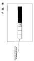
- Fig. 18 shows an example of the patch pattern output onto the recording medium in step S21.
- step S23 the gradation patch pattern shown in Fig. 18 output in step S22 is read by the original reading unit 202, and is converted into a luminance signal by the CCD 21.
- the luminance signal is LOG-converted by the LOG conversion unit 24 shown in Fig. 4, and the CPU 43 fetches the converted data as C, M, and Y density data.
- These density data will be referred to as "second density data (Dn2)" hereinafter.
- step S24 the relationships between the laser output levels and the second density data (Dn2) as the density values of the respective read gradation patch pattern portions in units of gradation levels of the patch pattern, i.e., the contents of the conversion table 42a of the luminance-density conversion unit 42 shown in Fig. 6, are obtained in correspondence with the coordinate system, and are stored in the RAM 212.
- step S25 the conversion table 42a is updated based on the contents stored in the RAM 212.
- Fig. 19 shows curves of only the table 42a corresponding to yellow, which is extracted from the conversion tables 42a to 42d shown in Fig. 12 above.
- the conversion table 42a is updated to shift the point d0 to the point d1 when k ⁇ 1 or to shift the point d0 to d2 when k > 1.
- the conversion table 42a can have data for 256 gradation levels.
- higher-order interpolation or higher-order approximation is more preferable to improve accuracy.
- Processing similar to the above-mentioned updating processing of the conversion table 42a is repetitively performed for the tables corresponding to required colors.
- the printer characteristics shown in the third quadrant in Fig. 5 are obtained.
- the ⁇ correction characteristics of the printer unit shown in the second quadrant in Fig. 5 are determined in units of densities, and contents corresponding to all the 256 gradation levels of the ⁇ -LUT 44 are set. More specifically, using the first density data (Dnl) obtained by re-measuring the patch pattern on the drum, the ⁇ -LUT 44 is generated again. In this manner, the second gradation correction control is completed.
- the density correction can be performed in consideration of the current printer characteristics irrespective of any change in reading characteristics of the measuring units 3a to 3d.
- the processing described in the second embodiment need only be performed upon adjustment in assembling of the apparatus or upon exchange of the photosensors 9a to 9d.
- the above-mentioned processing is preferably performed at appropriate time intervals.
- the second gradation correction control using the first and second density data Dn1 and Dn2 is performed in addition to the first gradation correction control of the first embodiment described above, an image which has good gradation characteristics over a long period of time, and also has not only a good color balance but also good reproduction densities can be formed.
- the third embodiment of the present invention will be described below.
- the hardware arrangement of the third embodiment is the same as that in the first embodiment, and a detailed description thereof will be omitted.
- the second embodiment has explained an example wherein a decrease in formed image density generated after a long term use of the printer unit 100 is corrected by performing correction control (second gradation correction control) for a single color designated by the operator.
- correction control second gradation correction control
- the second gradation correction control which is performed for only the designated color in the second embodiment, is performed for all the colors, i.e., yellow, magenta, cyan, and black at the same time.
- the second gradation correction control in the third embodiment i.e., the setting process of the luminance-density conversion tables 42a to 42d by the CPU 43, will be described below with reference to the flow chart in Fig. 20.
- the operator turns "ON" a start switch of the updating mode of the conversion tables using the operation panel 300 shown in Fig. 1, in step S31.
- step S32 the pattern generators 45 shown in Fig. 3 form multiple-gradation patch patterns for all the colors used on the corresponding photosensitive drums 1a to 1d, and the patterns are transferred and output onto a single recording medium.
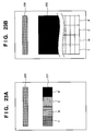
- Fig. 21 shows an example of the patch patterns output onto the recording medium in step S32.
- step S33 the gradation patch patterns shown in Fig. 21 output in step S32 is read by the original reading unit 202, and the read patterns are converted into luminance signals by the CCD 21.
- the luminance signals are LOG-converted by the LOG conversion unit 24 shown in Fig. 4, and the converted data are fetched by the CPU 43 as Y, M, and C density data. These density data will be referred to as "second density data (Dn2)" hereinafter.
- step S34 and the subsequent steps are performed for all the colors as those in step S24 and the subsequent steps of the second embodiment shown in Fig. 17, the luminance-density conversion tables 42a to 42d are appropriately updated, and the density correction can be attained in consideration of the current reading characteristics of the photosensors 9a to 9d and the current printer characteristics.
- step S4 the processing operations in step S4 and the subsequent steps shown in Fig. 13 are performed again, the second gradation correction control in the third embodiment is executed.
- the gradation characteristics for all the colors can be maintained by single processing. Furthermore, when this processing is performed periodically, an image which has good gradation characteristics over a long period of time, and also has not only a good color balance but also good reproduction densities can be formed.
- the ⁇ correction characteristics are set by forming a patch pattern on the photosensitive drum and reading the formed patch pattern.
- a patch pattern is formed on a recording sheet, and the formed pattern is read by the CCD sensor 21, thereby setting the ⁇ correction characteristics in consideration of the image forming condition on the recording sheet and the original reading characteristics of the CCD sensor 21. This processing will be referred to as a test print mode hereinafter.
- test print 1 is obtained by forming Y, M, C, and K maximum-density patches on a recording sheet, as shown in Fig. 23A.
- reference numeral 230 denotes a reference position mark; and 231, maximum-density patches in units of colors.
- Test print 1 is placed on the original table of the original reading unit 202, and the respective color patches are read by the CCD 21 (step S44).
- Y, M, C, and K data obtained by sequentially processing the read signals and output from the expansion units 281 to 284 are supplied to the CPU 43, and the CPU 43 calculates the contrast potentials used in the potential control shown in Fig. 13 of the first embodiment in correspondence with the respective color image forming units (step S45).
- test print 2 is output (step S47).
- Test print 2 is obtained by forming Y, M, C, and K 16-gradation patch patterns (reference numeral 232) on a recording sheet, as shown in Fig. 23B.
- Test print 2 is formed under the image forming condition calculated in step S45.
- Test print 2 is read as in step S44 (step S48), and Y, M, C, and K color patch read data obtained from the expansion units 281 to 284 are supplied to the CPU 43.
- the CPU 43 calculates data of the ⁇ -LUTs 44 and sets the calculated data in the ⁇ -LUTs 44 (step S49).
- a message "read to copy" is displayed (step S50), and a normal copy mode is restored.
- Test prints 1 and 2 of the fourth embodiment are also formed based on pattern data generated by the pattern generators 45 shown in Fig. 3.
- the pattern generators 45 for the respective colors are simultaneously operated in response to the ITOP signal, so that the respective color patch patterns for an identical density are parallelly formed.
- the pattern generators 45 are operated in the order of Y, M, C, and K with respect to the ITOP signal in consideration of the distances between adjacent ones of the photosensitive drums 1a to 1d.
- the ⁇ correction characteristics can be set in consideration of the image formation characteristics on the recording sheet, the original reading characteristics of the CCD 21, and the compression characteristics of the compression unit 26. At this time, since the patch patterns formed by the Y, M, C, and K color image forming units are read by the CCD 21 as a common reading means, a good color balance can be obtained.
- test print mode of the fourth embodiment may be assigned as an additional function of the control of the first embodiment described above.
- the present invention may be applied to either a system constituted by a plurality of equipments (e.g., a host computer, an interface device, a reader, a printer, and the like), or an apparatus consisting of a single equipment (e.g., a copying machine, a facsimile apparatus, or the like).
- equipments e.g., a host computer, an interface device, a reader, a printer, and the like
- an apparatus consisting of a single equipment e.g., a copying machine, a facsimile apparatus, or the like.
- the objects of the present invention can also be achieved by supplying a storage medium, which records a program code of a software program that can realize the functions of the above-mentioned embodiments to the system or apparatus, and reading out and executing the program code stored in the storage medium by a computer (or a CPU, MPU, or the like) of the system or apparatus.
- the program code itself read out from the storage medium realizes the functions of the above-mentioned embodiments, and the storage medium which stores the program code constitutes the present invention.
- the storage medium for supplying the program code for example, a floppy disk, hard disk, optical disk, magneto-optical disk, CD-ROM, CD-R, magnetic tape, nonvolatile memory card, ROM, and the like may be used.
- the functions of the above-mentioned embodiment may be realized not only by executing the readout program code by the computer but also by some or all of actual processing operations executed by an OS (operating system) running on the computer on the basis of an instruction of the program code.
- OS operating system
- the functions of the above-mentioned embodiments may be realized by some or all of actual processing operations executed by a CPU or the like arranged in a function extension board or a function extension unit, which is inserted in or connected to the computer and receives the program code read out from the storage medium.
- the storage medium stores program codes corresponding to the above-mentioned flow chart.
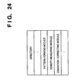
- modules shown in the memory map in Fig. 24 are stored in the storage medium. That is, at least a "pattern forming module”, a “density measuring module”, and a “gradation correcting module” can be stored in the storage medium.
- a laser printer has been exemplified.
- the present invention may be applied to an LED printer, an ink-jet printer, or the like, which has a plurality of image forming units for respectively forming a plurality of color images.
Landscapes
- Physics & Mathematics (AREA)
- General Physics & Mathematics (AREA)
- Engineering & Computer Science (AREA)
- Microelectronics & Electronic Packaging (AREA)
- Facsimile Image Signal Circuits (AREA)
- Color Electrophotography (AREA)
- Control Or Security For Electrophotography (AREA)
- Color, Gradation (AREA)
- Laser Beam Printer (AREA)
- Color Image Communication Systems (AREA)
Applications Claiming Priority (3)
| Application Number | Priority Date | Filing Date | Title |
|---|---|---|---|
| JP18419895 | 1995-07-20 | ||
| JP7184198A JPH0937080A (ja) | 1995-07-20 | 1995-07-20 | 画像処理装置及び方法 |
| JP184198/95 | 1995-07-20 |
Publications (2)
| Publication Number | Publication Date |
|---|---|
| EP0754980A2 true EP0754980A2 (de) | 1997-01-22 |
| EP0754980A3 EP0754980A3 (de) | 2001-03-21 |
Family
ID=16149079
Family Applications (1)
| Application Number | Title | Priority Date | Filing Date |
|---|---|---|---|
| EP96305336A Withdrawn EP0754980A3 (de) | 1995-07-20 | 1996-07-19 | Bildbehandlungsgerät und -verfahren |
Country Status (3)
| Country | Link |
|---|---|
| US (1) | US6148158A (de) |
| EP (1) | EP0754980A3 (de) |
| JP (1) | JPH0937080A (de) |
Families Citing this family (24)
| Publication number | Priority date | Publication date | Assignee | Title |
|---|---|---|---|---|
| JP3708363B2 (ja) * | 1999-05-07 | 2005-10-19 | シャープ株式会社 | カラー画像形成装置 |
| JP2002214978A (ja) * | 2001-01-18 | 2002-07-31 | Canon Inc | 画像形成装置およびリモート情報管理装置およびリモート情報収集装置およびリモート情報管理システムおよび画像形成装置の制御方法およびリモート情報管理装置の制御方法およびリモート情報収集装置の制御方法および記憶媒体 |
| US6771839B2 (en) | 2001-02-20 | 2004-08-03 | Sharp Laboratories Of America, Inc. | Efficient method of computing gamma correction tables |
| JP4860854B2 (ja) * | 2001-09-28 | 2012-01-25 | キヤノン株式会社 | カラー画像形成装置システム |
| CN1193270C (zh) * | 2001-09-10 | 2005-03-16 | 佳能株式会社 | 图像形成装置及其调整方法 |
| US6968148B2 (en) * | 2002-09-10 | 2005-11-22 | Sharp Kabushiki Kaisha | Image adjusting method and image forming apparatus |
| JP4564705B2 (ja) * | 2002-09-10 | 2010-10-20 | キヤノン株式会社 | カラー画像形成装置及びその制御方法、制御プログラム及び記憶媒体 |
| US6938550B2 (en) * | 2002-10-31 | 2005-09-06 | R. R. Donnelley & Sons, Co. | System and method for print screen tonal control and compensation |
| JP2005043617A (ja) * | 2003-07-28 | 2005-02-17 | Konica Minolta Business Technologies Inc | 画像形成装置 |
| JP4447871B2 (ja) * | 2003-08-29 | 2010-04-07 | キヤノン株式会社 | 画像形成装置 |
| JP4586369B2 (ja) * | 2004-01-23 | 2010-11-24 | 富士ゼロックス株式会社 | 画像形成装置の制御装置、制御方法及び制御プログラム |
| JP4360335B2 (ja) * | 2005-03-15 | 2009-11-11 | セイコーエプソン株式会社 | カラー画像形成装置、カラー画像形成システム、カラー画像処理方法及びプログラム |
| JP4310707B2 (ja) * | 2005-04-12 | 2009-08-12 | ノーリツ鋼機株式会社 | 階調変換較正方法及びこの方法を用いた階調変換較正モジュール |
| JP2007081750A (ja) * | 2005-09-13 | 2007-03-29 | Canon Inc | 画像形成装置及びその方法、並びにプログラム |
| JP4965961B2 (ja) * | 2006-10-12 | 2012-07-04 | キヤノン株式会社 | 画像形成装置 |
| US8531745B2 (en) | 2006-11-27 | 2013-09-10 | Canon Kabushiki Kaisha | Image formation density correction in image forming apparatus |
| JP5207712B2 (ja) * | 2006-11-27 | 2013-06-12 | キヤノン株式会社 | 画像形成装置 |
| JP5006625B2 (ja) * | 2006-12-01 | 2012-08-22 | キヤノン株式会社 | 画像形成装置 |
| US8014689B2 (en) * | 2007-05-18 | 2011-09-06 | Kyocera Mita Corporation | Image forming apparatus, method of gamma correction and storage medium storing gamma correction program |
| WO2014171456A1 (ja) * | 2013-04-17 | 2014-10-23 | コニカミノルタ株式会社 | 画像読取装置及び画像読取装置の補正方法 |
| JP2016167007A (ja) * | 2015-03-10 | 2016-09-15 | 株式会社リコー | 画像形成装置および画像形成装置の制御方法 |
| JP2017151170A (ja) * | 2016-02-22 | 2017-08-31 | キヤノン株式会社 | 画像形成装置、画像形成方法 |
| US10073397B2 (en) * | 2016-04-26 | 2018-09-11 | Canon Kabushiki Kaisha | Image forming apparatus and control method for updating conversion condition converting measurement result of measurement unit |
| JP2018092157A (ja) * | 2016-11-29 | 2018-06-14 | キヤノン株式会社 | 画像形成装置 |
Family Cites Families (16)
| Publication number | Priority date | Publication date | Assignee | Title |
|---|---|---|---|---|
| JP3276744B2 (ja) * | 1993-10-29 | 2002-04-22 | キヤノン株式会社 | 画像形成装置及びその方法 |
| DE3408336A1 (de) * | 1983-03-08 | 1984-09-13 | Canon K.K., Tokio/Tokyo | Bildreproduktionssystem |
| JPS6395471A (ja) * | 1986-10-09 | 1988-04-26 | Konica Corp | 多色像形成方法 |
| EP0449328B1 (de) * | 1990-03-30 | 1998-08-26 | Canon Kabushiki Kaisha | Bildverarbeitungsverfahren und -gerät |
| JP3155555B2 (ja) * | 1991-02-22 | 2001-04-09 | キヤノン株式会社 | カラー画像形成装置 |
| JP3143484B2 (ja) * | 1991-02-22 | 2001-03-07 | キヤノン株式会社 | 画像処理装置 |
| US5414531A (en) * | 1991-02-22 | 1995-05-09 | Canon Kabushiki Kaisha | Image forming control based on a stored operation condition |
| US5294959A (en) * | 1991-10-03 | 1994-03-15 | Canon Kabushiki Kaisha | Image forming apparatus with image density detection means for controlling image forming conditions |
| JPH0643729A (ja) * | 1992-03-04 | 1994-02-18 | Canon Inc | 転写材上に複数の色トナーによる多重像を形成する画像形成装置 |
| US5585927A (en) * | 1992-05-19 | 1996-12-17 | Minolta Camera Kabushiki Kaisha | Digital image forming apparatus having gradation characteristic setting means |
| JPH05333652A (ja) * | 1992-05-29 | 1993-12-17 | Canon Inc | 画像形成装置 |
| CA2106706C (en) * | 1992-09-28 | 1999-07-27 | Rie Saito | Image forming method and apparatus |
| JP3274200B2 (ja) * | 1992-12-28 | 2002-04-15 | キヤノン株式会社 | 画像形成方法及び装置 |
| JPH0756424A (ja) * | 1993-08-18 | 1995-03-03 | Konica Corp | 画像形成装置 |
| US5579090A (en) * | 1994-01-12 | 1996-11-26 | Canon Kabushiki Kaisha | In an image processing system, an image processing apparatus and method for stabilizing output image quality by controlling image forming parameters |
| JPH07264411A (ja) * | 1994-03-25 | 1995-10-13 | Canon Inc | 画像形成装置 |
-
1995
- 1995-07-20 JP JP7184198A patent/JPH0937080A/ja not_active Withdrawn
-
1996
- 1996-07-19 US US08/684,090 patent/US6148158A/en not_active Expired - Lifetime
- 1996-07-19 EP EP96305336A patent/EP0754980A3/de not_active Withdrawn
Also Published As
| Publication number | Publication date |
|---|---|
| JPH0937080A (ja) | 1997-02-07 |
| EP0754980A3 (de) | 2001-03-21 |
| US6148158A (en) | 2000-11-14 |
Similar Documents
| Publication | Publication Date | Title |
|---|---|---|
| US6148158A (en) | Image processing apparatus and method having a plurality of image forming units for performing image formation using predetermined colors | |
| EP0604941B1 (de) | Bilderzeugungsgerät | |
| EP2408189B1 (de) | Bildverarbeitungsvorrichtung und Steuerverfahren dafür | |
| US7230739B2 (en) | Image processing apparatus and method | |
| US8049932B2 (en) | Image forming apparatus and image density control method therefor | |
| US9659242B2 (en) | Apparatus that performs calibration for maintaining image quality | |
| CN102279535B (zh) | 能够进行精确灰度校正的图像形成设备 | |
| JP4379508B2 (ja) | 画像形成装置、階調補正方法、及び階調補正プログラム | |
| JP4371803B2 (ja) | 画像形成装置 | |
| US6785480B2 (en) | Image forming apparatus having a plurality of image forming speeds | |
| EP0679016B1 (de) | Bildverarbeitungsverfahren und -steuergerät | |
| JP5120402B2 (ja) | 画像形成装置及び画像形成方法 | |
| JP3154261B2 (ja) | 画像形成装置 | |
| JP3707505B2 (ja) | 光プリンタ | |
| US7031020B1 (en) | Image processing method, apparatus and controller | |
| JPH08289149A (ja) | 画像記録装置およびその方法 | |
| US6229969B1 (en) | Image forming apparatus and image forming method which controls an image forming condition depending on one type of image forming pattern | |
| JP4209704B2 (ja) | 画像形成装置、画像形成方法 | |
| US6538683B2 (en) | Image forming apparatus and a control method of an image forming apparatus | |
| JP3472257B2 (ja) | 画像処理方法、記録媒体 | |
| JPH0477060A (ja) | 画像形成装置 | |
| JP3567182B2 (ja) | デジタル画像形成装置 | |
| JPH07131649A (ja) | 画像形成装置 | |
| JPH06205217A (ja) | 画像作成装置 | |
| JPH07131651A (ja) | 画像形成装置 |
Legal Events
| Date | Code | Title | Description |
|---|---|---|---|
| PUAI | Public reference made under article 153(3) epc to a published international application that has entered the european phase |
Free format text: ORIGINAL CODE: 0009012 |
|
| AK | Designated contracting states |
Kind code of ref document: A2 Designated state(s): DE FR GB IT |
|
| PUAL | Search report despatched |
Free format text: ORIGINAL CODE: 0009013 |
|
| AK | Designated contracting states |
Kind code of ref document: A3 Designated state(s): DE FR GB IT |
|
| 17P | Request for examination filed |
Effective date: 20010806 |
|
| 17Q | First examination report despatched |
Effective date: 20050804 |
|
| STAA | Information on the status of an ep patent application or granted ep patent |
Free format text: STATUS: THE APPLICATION HAS BEEN WITHDRAWN |
|
| 18W | Application withdrawn |
Effective date: 20091214 |