EP0755100A2 - Jeu de contacts pour câble à paires torsadées blindées individuellement - Google Patents
Jeu de contacts pour câble à paires torsadées blindées individuellement Download PDFInfo
- Publication number
- EP0755100A2 EP0755100A2 EP96305364A EP96305364A EP0755100A2 EP 0755100 A2 EP0755100 A2 EP 0755100A2 EP 96305364 A EP96305364 A EP 96305364A EP 96305364 A EP96305364 A EP 96305364A EP 0755100 A2 EP0755100 A2 EP 0755100A2
- Authority
- EP
- European Patent Office
- Prior art keywords
- connector
- contact
- pair
- cable
- pairs
- Prior art date
- Legal status (The legal status is an assumption and is not a legal conclusion. Google has not performed a legal analysis and makes no representation as to the accuracy of the status listed.)
- Granted
Links
Images




Classifications
-
- H—ELECTRICITY
- H01—ELECTRIC ELEMENTS
- H01R—ELECTRICALLY-CONDUCTIVE CONNECTIONS; STRUCTURAL ASSOCIATIONS OF A PLURALITY OF MUTUALLY-INSULATED ELECTRICAL CONNECTING ELEMENTS; COUPLING DEVICES; CURRENT COLLECTORS
- H01R13/00—Details of coupling devices of the kinds covered by groups H01R12/70 or H01R24/00 - H01R33/00
- H01R13/648—Protective earth or shield arrangements on coupling devices, e.g. anti-static shielding
- H01R13/658—High frequency shielding arrangements, e.g. against EMI [Electro-Magnetic Interference] or EMP [Electro-Magnetic Pulse]
- H01R13/6581—Shield structure
- H01R13/6585—Shielding material individually surrounding or interposed between mutually spaced contacts
Definitions
- the present invention relates to a contact set which comprises a female and a male contact part, to be used in connection with multi-pair cables with individually shielded pairs.
- the contact set of the invention may provide a coupling from a multi-pair shielded pair cable to a printed circuit board (PCB), or a coupling between two cable parts.
- PCB printed circuit board
- the contact set is suited to be entered as part of a wideband communications equipment.
- TP twisted pair cable
- Cabling systems based on TP are standardized internationally for bandwidths up to 100 MHz. These standards define the quality requirements for both cable and connecting hardware.
- the connector used is the RJ45 connector, designed for use with a 4 pair cable.
- the standardization body Cenelec has defined the cable and connector requirements, mainly through the norm EN 50173.
- the RJ45 connector is standardized both with respect to design and to electrical performance.
- TP has not been standardized.
- Some cable manufacturers have started the marketing of cables capable of transmitting signals with frequencies up to at least 300 MHz. In some cases, 600 MHz appears feasible.
- the cable uses an aluminum foil screen around each pair.
- the cable often has an overall braided screen. When used with data equipment, the combined foil and braid screens give the cable excellent immunity against external electromagnetic disturbances and a low level of emission (EMC).
- RJ45 connector can possibly be improved, but in any case a limit will be found around 2-300 MHz, where the crosstalk between the contact pins - pair vs. pair - becomes too high.
- IBM has marketed a cabling system claiming usable performance up to 300 MHz.
- the system uses a set of connectors called "MiniC".
- MiniC set of connectors
- the object of the present invention is to provide a contact set which overcomes the above limitations, and which provides good transmission characteristics up to and possibly beyond 600 MHz.
- the contact set of the invention consists essentially of a male connector or plug containing contact pins, and a female connector or jack containing contact receptacles intended for direct engagement or mating with the contact pins.
- pins dictate a “plug” type connector
- receptacles define a “jack” type connector, even if surrounding shield covers may be arranged in such a manner that the shield cover of a "plug/male connector” actually receives the shield cover of a "jack/female connector” for inside mating.
- the contact set has two general aspects, namely the aspect of providing a connection between a multi-pair pair cable and a printed circuit board (PCB) (or more generally, a fixed electrical assembly), and the aspect of providing a connection between two such pair cables.
- the first aspect can be divided into two specific embodiments, namely (a) one in which one of the connectors in the contact set is a PCB-mounted plug with pins soldered directly to the board, while the other connector is a cable-mounted jack having contact receptacles.
- the second embodiment of the first aspect includes (b) a PCB-mounted jack with receptacles soldered directly to the board, while the other connector is a cable-mounted plug having contact pins.
- the second aspect i.e. the cable-to-cable aspect, branches off into four separate embodiments:
- One single cable connector may be
- type I can mate with only type III, and type II must mate with type IV.
- a cable having a type I connector must be used to mate with a PCB connector of type (b) (see above), and a cable with a type IV connector must mate with a type (a) PCB connector.
- a PCB connector one does not include as a favourable embodiment the embodiment with a "male” type shield cover, the "female” type shield cover is preferable for a PCB-mounted connector.
- the invention will also include the option of a "male" type shield cover for a PCB connector.
- the embodiment most often referred to is an embodiment having a square-shaped shield cover cross section, i.e. as appearing e.g. in the lower part of fig. 4, but it should be realized that the cross section may in general be rectangular, plural-edged or even having curved outer boundaries.
- the connectors contain exactly four pairs of contact pins or contact receptacles, any number of pairs from 2 and up is encompassed by the invention.
- the essential points are (i) a specified mutual geometrical layout of the pairs inside a connector, and (ii) the presence of inter-pair shielding as specified further herebelow, by means of at least one shield kernel member and springy metal tongues.
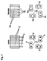
- this figure shows the principal layout of essential parts of an embodiment of a cable plug and a cable jack in accordance with the invention. As mentioned above, this embodiment is a 4-pair quadratic embodiment.
- the left side part of fig. 1 shows a cable plug layout.
- the bottom drawing contains in a front view four pairs of parallel contact pins 3, the pins pointing right out of the paper plane.
- the contact pins 3 are inserted two by two in insulating holder parts 2, preferably made of a plastic material.
- each such holder 2 has the shape of a right-angled parallelepiped.
- this holder shape is particularly adapted for the 4-pair quadratic embodiment, and other shapes may be opportune in other embodiments, e.g. a curved shape on one side may give a better fit to a surrounding structure (shield cover, see below) in some embodiments.
- top left drawing shows the same parts as the bottom drawing, however in a side view. It appears that the pins 3 project below (or more correctly, forwardly of) the plastic holders 2.
- each pair of contact pins is arranged at a 90° angle relative to the nearest pair or both nearest pairs. (To be more specific, the orientation of each pair, where "orientation” is defined as the direction associated with the spacing between single pins in a pair of parallel pins, is turned 90° from one pair to the next-neighbour pair.)
- the right side part of fig. 1 shows the layout of corresponding parts in a cable jack or female connector, i.e. corresponding to the layout for the plug parts shown on the left side of the drawing.
- the lower drawing appear, in a front view, four pairs of parallel contact receptacles 13, geometrically arranged in a similar manner as the contact pins 3 in the plug on the left.
- the receptacles 13 are mounted in separate insulating holder parts 12, preferably plastic holders. The same arrangement is shown in a side view in the top right drawing.
- Each wire of the pair cable (in this embodiment a four-pair cable) is attached to the rear end of a contact pin 3 or a contact receptacle 13 by soldering, displacement or by crimp.
- Pins and receptacles can be commercially available products, and they are usually gold plated.
- the receptacles 13 preferably rely on some sort of spring action in order to secure good electrical contact when interfaced with the pins.
- the receptacles thus may be shaped as elongate, open-ended cylinders with a split along the length thereof, or as similar cylinders with an internal spring part.
- the pins 3 are preferably solid, elongate cylinders or hollow cylinders.
- the "orientation twist" from one pin pair/receptacle pair to the neighbour pair constitutes an important characteristic of the invention. This characteristic contributes strongly to keep the crosstalk between the pairs low, in particular because the coupling due to magnetic fields is minimized.
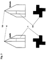
- fig. 3 The left side of fig. 3 shows a metallic or highly conductive body 2 which forms a shield kernel member to be placed inside a plug/male connector exhibiting the arrangement appearing in fig. 1, left part.
- the forward part of the kernel member 1 has a cross section such as appears in the lower left drawing, however the excact shape of the kernel member is only of top importance as far as concerns the necessity of the existence of a metallic kernel member inbetween the pin pairs shown in fig. 1.
- the specific shape shown in fig. 3 has been chosen so as to be adapted to the specific pin holders 2 arranged as shown in fig. 1, i.e. the kernel member fits rather exactly inbetween the plastic holders, having a cross section shaped as a "disaligned cross".
- the pyramidal shape in the rear part of the kernel member 1, tapering off to a point 4 is chosen to provide guidance and support for the cable pairs from a point of entrance into a plug, near said point 4, and forward to the rear end of each separate pin in the plug.
- This shape is not paramount to the invention, but represents a preferred embodiment.
- the kernel member 1 is preferably made from a solid piece of metal, preferably copper, aluminum or zinc, and preferably with a tinned surface.
- a solid piece of metal preferably copper, aluminum or zinc, and preferably with a tinned surface.
- a quite similar shield member 11 for the corresponding cable jack/female connector All statements regarding kernel member 1 have corresponding statements regarding kernel member 11.
- fig. 4 are shown arrangements of plastic holder parts 2 and 12 around each kernel member 1 and 11, actually in corners of the above mentioned “disaligned cross" of the kernel members 1 and 11.
- the holder parts may be kept in position (e.g. while assembling a connector) for instance by small cavities in the kernel member (not shown in the drawings) and corresponding "bulbs" on the holder parts.
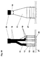
- Fig. 5 shows a preferred connection configuration of cable pairs to respectively pins 3 and receptacles 13 for a cable splicing contact set. It appears clearly that fig. 5 represents a continuation of figs. 1, 3 and 4. The connections are made by crimp, displacements or soldering techniques. As previously mentioned, the pyramidal prolongation of the kernel members acts as a guide for the cable pairs 5 and 15, and also secures good electrical contact between the kernel members 1, 11 and the (metallic) foil screens 6 and 16 surrounding each cable pair. These guiding/support features are important and preferred additional features of the invention.
- Reference numeral 20 designates an overall (metallic) cable screen.
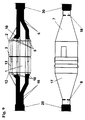
- FIG. 6 and 7 The left part of these drawings shows embodiments of shield covers 17 and 7, which two shield covers are cable connector covers, adapted to cooperate with connector inside parts as shown in figs. 1, 3, 4 and 5.
- the shield covers are typically made from 0,3 mm thick, springy metal sheets as single - or possibly two - piece units.
- Each shield cover 7, 17 is folded around a kernel member 1, 11, including plastic holders 2, 12 having pins/receptacles 3/13, as well as a cable.
- each shield cover has a section which is adapted as a split circular clamp 8, 18 to be crimped around the cable pairs in order to provide strain relief and electrical contact with the cable foil screens 6 and 16, see the top right drawing in figs. 6 and 7, indicating a cross section view taken at the line A-A in the left side drawing.
- the shield cover 7 in fig. 7 is adapted to receive the shield cover 17 in fig. 6 inside a forward extended part appearing below (in the drawing) the B-B line in fig. 7.
- fig. 6 nevertheless shows a female connector having receptacles 13
- fig. 7 shows a male connector having contact pins 3.
- matters may be reversed.
- the forward extended part of the plug/male connector shown in fig. 7 has a shape for receiving the other shield cover, with splits at each corner and some bending outward laterally, to act as a flexing guide for the other connector.
- the extension is also able to protect the protruding contact pins by providing a square "fence" around them.
- a paramount feature of the invention also appears in fig. 7, namely the metal tongues 10 which in this embodiment of the invention are provided by partly stamping or cutting a piece from each side of shield cover 7 and shaping and folding these pieces approximately 90 degrees inwards.
- These tongues 10 now act as contact springs against the kernel member 11 in the other connector, i.e. in a mated state.
- the contact springs 10 will be pinched between two kernels, providing a very good electrical contact.
- the tongues/contact springs 10 constitute an important and characterizing part of the invention, since they provide a low-ohmic electrically continuous interface between (in this embodiment) the plug and jack shield kernels, or generally between the one necessary shield kernel of a cable-mounted connector and the shield system of the counterpart connector, whether it is another cable-mounted connector or a connector mounted on some other electrical system part, e.g. a printed circuit board.
- the contact tongues 10 appear in the left side drawing as dotted lines, while a cross section view along line B-B, see the lower right part of fig. 1, shows the tongues 10 substantially filling up the area between the plastic holders 2, and with bend lines indicated.
- Figs. 9 og 11 show a mated state for the connectors previously shown in figs. 6 and 7.
- the top part of fig. 9 shows an "X-ray" view through the contact set embodiment, with contact pins 3 entered properly into contact receptacles 13.
- the lower part of fig. 9 shows the same situation with intercorrected cable connectors, however with a view to the shield covers 7 and 17, where cover 17 has been guided into receiving cover 7.
- contact springs 10 are now in a pinched situation between two shield kernels.
- fig. 11 shows the interconnection of the cable plug and the cable jacket in a complete assembly where both connectors are provided with an overall insulating cover 9, 10, preferably of a plastic material.
- insulating covers can be mounted e.g. by first threading a cover over the cable before assembling the connector, and thereafter pulling the cover back over the metal shield cover of the connector.
- the insulating cover 9, 19 can be moulded directly onto the connector after assembly thereof.
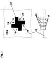
- figs. 2, 8, 10 and 12 The embodiment appearing in figs. 2, 8, 10 and 12 is a square-shaped embodiment, however, as previously stated, this square shape is not a prerequisite.
- a printed circuit board 21 has soldered to it contact pins 23, however contact receptacles would be possible in the same positions.
- the lower part of fig. 2 shows the PCB 21 in a side view.
- Reference numeral 25 designates solder points for the contact pins, which are inserted into holes in the PCB with a tight fit, and soldered to provide electrical connection to circuits on the PCB. Pin pairs use the same spacings and the same orientation relative to the nearest neighbours, as in the case with the cable-mount connectors, see the top part of fig. 2 which is a front view.
- Reference numeral 22 designates a conducting ground plane on the PCB, having a specific shape designed to interface with the shield kernel of the cable mount connector to be mated with the PCB connector.
- This PCB connector is designed to mate with just such a connector as appears in fig. 6, and therefore the ground plane 22 has the previously mentioned “disaligned cross" shape.
- metal tongues see below will be provided between the ground plane 22 and the mating shield kernel, to establish a springy type interface therebetween.
- the PCB connector of fig. 1 has had added to it a shield cover 27 made from the same material as the shield cover of the cable-mounted connectors.
- This shield cover 27 has a "fence" configuration around the contact pins 23, and it has partly split corners to provide a guiding function for the mating cable-mounted connector, which in the case shown will be a female connector.
- Extensions on the PCB edge of the shield cover 27 are folded inward and shaped to provide contact springs (tongues) 26 similar to the ones mentioned in the cable-mount embodiment described above.
- the contact springs 26 establish a low-ohmic, electrically continuous interface between the kernel member of the mating cable-mounted connector and the PCB ground plane area 22 (fig. 2).
- the shield cover 27 also has soldering pins 24, shown in the lower part of fig. 8, for soldering to the PCB 21.
- the contact springs 26 appear as dotted, curved lines in the lower drawing, which is a side view, and appear clearly with bend lines in the front view shown in the top drawing of fig. 8.
- Figs. 10 and 12 show, in a similar manner as figs. 9 and 11, the interconnection of the PCB connector and the cable-mounted connector, in fig. 10 with an "X-ray" side view in the left side part, showing contact pins 23 entered properly into contact receptacles 13 in the plastic holders 12 of the cable-mounted connector.
- fig. 12 shows exactly the same interconnected situation, however as a complete assembly where the cable-mounted connector has been provided with an overall plastic cover 19. Usually a PCB connector will not need a similar insulating cover.
- a typical dimension for a practical connector as embodied above would be a square side edge equal to about 10 mm, while the spacing between two contact pins in a pin pair might be about 2 mm.
- the electrical specifications given in the table below indicate that as a minimum, the electrical specifications given in the table below, will be complied with: Frequency 300 MHz 450 MHz 600 MHz Near End Cross Talk (NEXT) 74 dB 71 dB 70 dB Attenuation 0.5 dB 0.7 dB 1.0 dB Return Loss 14 dB 14 dB 14 dB 14 dB 14 dB
- the invention also will encompass a cable splicing contact set in which only one of the connectors contains a shield kernel member, while the opposite connector does not contain such a kernel member, but is equipped with inward projecting metal tongues between the pin/receptacle pairs of this opposite connector, which opposite connector may then have a shape e.g. similar to a PCB-mounted connector as described hereabove, but with wires attached to the rear end of the pins/receptacles.
Landscapes
- Coupling Device And Connection With Printed Circuit (AREA)
- Details Of Connecting Devices For Male And Female Coupling (AREA)
- Multi-Conductor Connections (AREA)
- Communication Cables (AREA)
Applications Claiming Priority (2)
| Application Number | Priority Date | Filing Date | Title |
|---|---|---|---|
| NO960840 | 1996-02-29 | ||
| NO960840A NO301254B1 (no) | 1996-02-29 | 1996-02-29 | Kontaktsett for kopling av parkabel til et kretskort |
Publications (3)
| Publication Number | Publication Date |
|---|---|
| EP0755100A2 true EP0755100A2 (fr) | 1997-01-22 |
| EP0755100A3 EP0755100A3 (fr) | 1999-01-07 |
| EP0755100B1 EP0755100B1 (fr) | 2002-05-22 |
Family
ID=19899101
Family Applications (1)
| Application Number | Title | Priority Date | Filing Date |
|---|---|---|---|
| EP96305364A Expired - Lifetime EP0755100B1 (fr) | 1996-02-29 | 1996-07-22 | Jeu de contacts pour câble à paires torsadées blindées individuellement |
Country Status (5)
| Country | Link |
|---|---|
| US (1) | US5766040A (fr) |
| EP (1) | EP0755100B1 (fr) |
| AT (1) | ATE218013T1 (fr) |
| DE (2) | DE69621289T2 (fr) |
| NO (1) | NO301254B1 (fr) |
Cited By (10)
| Publication number | Priority date | Publication date | Assignee | Title |
|---|---|---|---|---|
| EP0940890A1 (fr) * | 1998-02-04 | 1999-09-08 | Alcatel | Jeu de contacts |
| WO1999056352A3 (fr) * | 1998-04-29 | 2000-02-03 | Litton Systems Inc | Systeme d'interconnexion electrique extremement dense possedant une capacite amelioree de mise a la terre et de limitation diaphonique |
| EP0993082A1 (fr) * | 1998-09-29 | 2000-04-12 | Alcatel | Connecteur modulaire à diaphonie réduite et adapté pour être utilisé avec des jeux de contacts différents |
| US6116965A (en) * | 1998-02-27 | 2000-09-12 | Lucent Technologies Inc. | Low crosstalk connector configuration |
| US6224423B1 (en) | 1998-01-15 | 2001-05-01 | The Siemon Company | Enhanced performance telecommunications connector |
| FR2814598A1 (fr) * | 2000-09-27 | 2002-03-29 | Fci France | Connecteur muni de contacts montes dans un isolant adapte |
| US6629858B2 (en) | 1998-01-15 | 2003-10-07 | The Siemon Company | Enhanced performance telecommunications connector |
| US6780054B2 (en) | 1998-01-15 | 2004-08-24 | The Siemon Company | Shielded outlet having contact tails shield |
| WO2003075287A3 (fr) * | 2002-03-07 | 2004-09-23 | Eugene Howe | Cable de connexion |
| US9502796B2 (en) | 2010-08-13 | 2016-11-22 | Harting Electronics Gmbh & Co. Kg | Plug connector for differential data transmission |
Families Citing this family (20)
| Publication number | Priority date | Publication date | Assignee | Title |
|---|---|---|---|---|
| US6077122A (en) | 1997-10-30 | 2000-06-20 | Thomas & Bett International, Inc. | Electrical connector having an improved connector shield and a multi-purpose strain relief |
| US6409547B1 (en) | 1998-12-02 | 2002-06-25 | Nordx/Cdt, Inc. | Modular connectors with compensation structures |
| CA2296953A1 (fr) * | 1999-01-28 | 2000-07-28 | Berg Technology, Inc. | Connecteur electrique pouvant etre connecte selon diverses orientations |
| CN1237668C (zh) * | 2001-01-29 | 2006-01-18 | 蒂科电子公司 | 高密度插座接插件 |
| US6783386B2 (en) | 2002-08-22 | 2004-08-31 | International Business Machines Corporation | Strain relief device for an electrical connector for high frequency data signals |
| US7267585B2 (en) * | 2005-03-24 | 2007-09-11 | International Business Machines Corporation | Method and system for easing attachment of a peripheral cable to a personal computer |
| DE202005016198U1 (de) * | 2005-10-15 | 2005-12-29 | Saurer Gmbh & Co. Kg | Zwirnflügel |
| US8182294B2 (en) | 2007-05-07 | 2012-05-22 | Ortronics, Inc. | Connector assembly and related methods of use |
| US7628657B2 (en) | 2007-05-07 | 2009-12-08 | Ortronics, Inc. | Connector assembly for use with plugs and preterminated cables |
| US8758047B2 (en) | 2007-05-07 | 2014-06-24 | Ortronics, Inc. | Port replication assembly with adapter cable and related methods of use |
| US7601024B2 (en) | 2007-05-07 | 2009-10-13 | Ortronics, Inc. | Shielded connector assembly for preterminated systems |
| WO2009032144A2 (fr) * | 2007-08-28 | 2009-03-12 | General Dynamics Advanced Information Systems, Inc. | Système et procédé d'interconnexion de cartes de circuits imprimés |
| US8674227B2 (en) * | 2008-08-08 | 2014-03-18 | Tyco Electronics Corporation | High performance cable splice |
| US7736159B1 (en) | 2009-04-07 | 2010-06-15 | Tyco Electronics Corporation | Pluggable connector with differential pairs |
| US7794290B1 (en) * | 2009-07-21 | 2010-09-14 | Adtran, Inc. | Communications connector configured for low crosstalk |
| US8241068B2 (en) * | 2010-08-30 | 2012-08-14 | Tyco Electronics Corporation | Pluggable connector with differential pairs having an air core |
| US8460024B2 (en) | 2011-03-14 | 2013-06-11 | Tyco Electronics Corporation | Contact assembly for electrical connector |
| CN102437483B (zh) * | 2011-09-14 | 2014-10-22 | 中国航空工业集团公司西安飞机设计研究所 | 一种新型电连续全屏蔽can总线连接方法 |
| DE102011055509B4 (de) * | 2011-11-18 | 2017-09-07 | Phoenix Contact Gmbh & Co. Kg | Steckverbinder |
| DE202012008970U1 (de) * | 2012-09-18 | 2012-10-17 | Rosenberger Hochfrequenztechnik Gmbh & Co. Kg | Steckverbinder |
Family Cites Families (5)
| Publication number | Priority date | Publication date | Assignee | Title |
|---|---|---|---|---|
| ATE143533T1 (de) * | 1988-05-13 | 1996-10-15 | Connector Systems Tech Nv | Steckverbindersystem für mehrere elektrische leiter |
| GB9003241D0 (en) * | 1990-02-13 | 1990-04-11 | Gore W L & Ass Uk | Shielded connector |
| NL9000578A (nl) * | 1990-03-14 | 1991-10-01 | Burndy Electra Nv | Connectorsamenstel voor printkaarten. |
| US5057038A (en) * | 1990-09-24 | 1991-10-15 | Molex Incorporated | Shielded electrical connection |
| NL9300971A (nl) * | 1993-06-04 | 1995-01-02 | Framatome Connectors Belgium | Connectorsamenstel voor printkaarten. |
-
1996
- 1996-02-29 NO NO960840A patent/NO301254B1/no not_active IP Right Cessation
- 1996-07-22 EP EP96305364A patent/EP0755100B1/fr not_active Expired - Lifetime
- 1996-07-22 DE DE69621289T patent/DE69621289T2/de not_active Expired - Fee Related
- 1996-07-22 AT AT96305364T patent/ATE218013T1/de not_active IP Right Cessation
- 1996-07-22 US US08/684,051 patent/US5766040A/en not_active Expired - Fee Related
- 1996-07-22 DE DE0755100T patent/DE755100T1/de active Pending
Cited By (20)
| Publication number | Priority date | Publication date | Assignee | Title |
|---|---|---|---|---|
| US6224423B1 (en) | 1998-01-15 | 2001-05-01 | The Siemon Company | Enhanced performance telecommunications connector |
| US6780054B2 (en) | 1998-01-15 | 2004-08-24 | The Siemon Company | Shielded outlet having contact tails shield |
| US6629858B2 (en) | 1998-01-15 | 2003-10-07 | The Siemon Company | Enhanced performance telecommunications connector |
| US6328601B1 (en) | 1998-01-15 | 2001-12-11 | The Siemon Company | Enhanced performance telecommunications connector |
| EP0940890A1 (fr) * | 1998-02-04 | 1999-09-08 | Alcatel | Jeu de contacts |
| US6193533B1 (en) | 1998-02-04 | 2001-02-27 | Alcatel | Contact set |
| US6116965A (en) * | 1998-02-27 | 2000-09-12 | Lucent Technologies Inc. | Low crosstalk connector configuration |
| US6179663B1 (en) | 1998-04-29 | 2001-01-30 | Litton Systems, Inc. | High density electrical interconnect system having enhanced grounding and cross-talk reduction capability |
| GB2353908A (en) * | 1998-04-29 | 2001-03-07 | Litton Systems Inc | High density electrical interconnect system having enhanced grounding and cross-talk reduction capability |
| GB2353908B (en) * | 1998-04-29 | 2002-08-07 | Litton Systems Inc | High density electrical interconnect system having enhanced grounding and cross-talk reduction capability |
| WO1999056352A3 (fr) * | 1998-04-29 | 2000-02-03 | Litton Systems Inc | Systeme d'interconnexion electrique extremement dense possedant une capacite amelioree de mise a la terre et de limitation diaphonique |
| US6162077A (en) * | 1998-09-29 | 2000-12-19 | Alcatel | Modular connector with reduced crosstalk and adapted to be used in different contact sets |
| EP0993082A1 (fr) * | 1998-09-29 | 2000-04-12 | Alcatel | Connecteur modulaire à diaphonie réduite et adapté pour être utilisé avec des jeux de contacts différents |
| FR2814598A1 (fr) * | 2000-09-27 | 2002-03-29 | Fci France | Connecteur muni de contacts montes dans un isolant adapte |
| EP1193812A1 (fr) * | 2000-09-27 | 2002-04-03 | Fci | Connecteur muni de contacts montés dans un isolant adapté |
| US6616482B2 (en) | 2000-09-27 | 2003-09-09 | Fci | Connector provided with contacts mounted in an adapted insulator |
| EP1641089A3 (fr) * | 2000-09-27 | 2006-05-31 | Souriau | Connecteur muni de contacts montés dans un isolant adapté |
| WO2003075287A3 (fr) * | 2002-03-07 | 2004-09-23 | Eugene Howe | Cable de connexion |
| CN100395846C (zh) * | 2002-03-07 | 2008-06-18 | 尤金·豪 | 互连电缆 |
| US9502796B2 (en) | 2010-08-13 | 2016-11-22 | Harting Electronics Gmbh & Co. Kg | Plug connector for differential data transmission |
Also Published As
| Publication number | Publication date |
|---|---|
| DE69621289D1 (de) | 2002-06-27 |
| DE755100T1 (de) | 1997-10-09 |
| US5766040A (en) | 1998-06-16 |
| NO960840L (no) | 1997-09-01 |
| NO301254B1 (no) | 1997-09-29 |
| DE69621289T2 (de) | 2003-01-02 |
| NO960840D0 (no) | 1996-02-29 |
| EP0755100B1 (fr) | 2002-05-22 |
| ATE218013T1 (de) | 2002-06-15 |
| EP0755100A3 (fr) | 1999-01-07 |
Similar Documents
| Publication | Publication Date | Title |
|---|---|---|
| EP0755100B1 (fr) | Jeu de contacts pour câble à paires torsadées blindées individuellement | |
| US6739904B2 (en) | Cable connector assembly | |
| US6468089B1 (en) | Solder-less printed circuit board edge connector having a common ground contact for a plurality of transmission lines | |
| US8632357B2 (en) | High data rate electrical connector and cable asssembly | |
| US8007317B2 (en) | Cable connector assembly with an improved shell | |
| US4611878A (en) | Electrical plug connector | |
| US7722399B2 (en) | Connector apparatus | |
| US5267868A (en) | Shielded electrical connector assemblies | |
| US6042394A (en) | Right-angle connector | |
| US10777936B2 (en) | Electrical device having a ground termination component with strain relief | |
| EP0969570A1 (fr) | Terminaison d'un blindage pour connecteur | |
| US6780054B2 (en) | Shielded outlet having contact tails shield | |
| US6966797B2 (en) | High-speed cable assembly | |
| US10069249B2 (en) | Cable apparatus | |
| US11545786B2 (en) | Cable shield for an electrical connector | |
| US8033866B2 (en) | Receptacle connector having reinforced bracket increasing overall rigidity | |
| US7261592B2 (en) | Electrical connector | |
| US6146153A (en) | Adapter apparatus and method for transmitting electronic data | |
| US4422700A (en) | Grounded multi-pin connector for shielded flat cable | |
| US6368151B1 (en) | Electrical connector assembly | |
| US11239611B2 (en) | Cable assembly with dielectric clamshell connector for impedance control | |
| JPH02177278A (ja) | 電気接続装置およびヘッダー | |
| US20240347982A1 (en) | Cable card assembly of an electrical connector having capacitors | |
| US6375496B1 (en) | Double stack electrical connector with integral ground plane | |
| US5078619A (en) | Coaxial cable terminal |
Legal Events
| Date | Code | Title | Description |
|---|---|---|---|
| PUAI | Public reference made under article 153(3) epc to a published international application that has entered the european phase |
Free format text: ORIGINAL CODE: 0009012 |
|
| AK | Designated contracting states |
Kind code of ref document: A2 Designated state(s): AT BE CH DE DK ES FI FR GB GR IE IT LI LU MC NL PT SE |
|
| AX | Request for extension of the european patent |
Free format text: AL PAYMENT 960809;LT PAYMENT 960809;LV PAYMENT 960809;SI PAYMENT 960809 |
|
| TCAT | At: translation of patent claims filed | ||
| RHK1 | Main classification (correction) |
Ipc: H01R 13/658 |
|
| DET | De: translation of patent claims | ||
| PUAL | Search report despatched |
Free format text: ORIGINAL CODE: 0009013 |
|
| AK | Designated contracting states |
Kind code of ref document: A3 Designated state(s): AT BE CH DE DK ES FI FR GB GR IE IT LI LU MC NL PT SE |
|
| AX | Request for extension of the european patent |
Free format text: AL PAYMENT 960809;LT PAYMENT 960809;LV PAYMENT 960809;SI PAYMENT 960809 |
|
| 17P | Request for examination filed |
Effective date: 19990628 |
|
| 17Q | First examination report despatched |
Effective date: 20000530 |
|
| GRAG | Despatch of communication of intention to grant |
Free format text: ORIGINAL CODE: EPIDOS AGRA |
|
| GRAG | Despatch of communication of intention to grant |
Free format text: ORIGINAL CODE: EPIDOS AGRA |
|
| GRAG | Despatch of communication of intention to grant |
Free format text: ORIGINAL CODE: EPIDOS AGRA |
|
| GRAH | Despatch of communication of intention to grant a patent |
Free format text: ORIGINAL CODE: EPIDOS IGRA |
|
| GRAH | Despatch of communication of intention to grant a patent |
Free format text: ORIGINAL CODE: EPIDOS IGRA |
|
| GRAA | (expected) grant |
Free format text: ORIGINAL CODE: 0009210 |
|
| AX | Request for extension of the european patent |
Free format text: AL PAYMENT 19960809;LT PAYMENT 19960809;LV PAYMENT 19960809;SI PAYMENT 19960809 |
|
| PG25 | Lapsed in a contracting state [announced via postgrant information from national office to epo] |
Ref country code: NL Free format text: LAPSE BECAUSE OF FAILURE TO SUBMIT A TRANSLATION OF THE DESCRIPTION OR TO PAY THE FEE WITHIN THE PRESCRIBED TIME-LIMIT Effective date: 20020522 Ref country code: IT Free format text: LAPSE BECAUSE OF FAILURE TO SUBMIT A TRANSLATION OF THE DESCRIPTION OR TO PAY THE FEE WITHIN THE PRE;WARNING: LAPSES OF ITALIAN PATENTS WITH EFFECTIVE DATE BEFORE 2007 MAY HAVE OCCURRED AT ANY TIME BEFORE 2007. THE CORRECT EFFECTIVE DATE MAY BE DIFFERENT FROM THE ONE RECORDED.SCRIBED TIME-LIMIT Effective date: 20020522 Ref country code: GR Free format text: LAPSE BECAUSE OF FAILURE TO SUBMIT A TRANSLATION OF THE DESCRIPTION OR TO PAY THE FEE WITHIN THE PRESCRIBED TIME-LIMIT Effective date: 20020522 Ref country code: FI Free format text: LAPSE BECAUSE OF FAILURE TO SUBMIT A TRANSLATION OF THE DESCRIPTION OR TO PAY THE FEE WITHIN THE PRESCRIBED TIME-LIMIT Effective date: 20020522 Ref country code: BE Free format text: LAPSE BECAUSE OF FAILURE TO SUBMIT A TRANSLATION OF THE DESCRIPTION OR TO PAY THE FEE WITHIN THE PRESCRIBED TIME-LIMIT Effective date: 20020522 Ref country code: AT Free format text: LAPSE BECAUSE OF FAILURE TO SUBMIT A TRANSLATION OF THE DESCRIPTION OR TO PAY THE FEE WITHIN THE PRESCRIBED TIME-LIMIT Effective date: 20020522 |
|
| REF | Corresponds to: |
Ref document number: 218013 Country of ref document: AT Date of ref document: 20020615 Kind code of ref document: T |
|
| REG | Reference to a national code |
Ref country code: GB Ref legal event code: FG4D |
|
| RIC1 | Information provided on ipc code assigned before grant |
Free format text: 7H 01R 13/658 A, 7H 01R 12/16 B |
|
| REG | Reference to a national code |
Ref country code: CH Ref legal event code: EP |
|
| REG | Reference to a national code |
Ref country code: IE Ref legal event code: FG4D |
|
| REF | Corresponds to: |
Ref document number: 69621289 Country of ref document: DE Date of ref document: 20020627 |
|
| PG25 | Lapsed in a contracting state [announced via postgrant information from national office to epo] |
Ref country code: LU Free format text: LAPSE BECAUSE OF NON-PAYMENT OF DUE FEES Effective date: 20020722 Ref country code: IE Free format text: LAPSE BECAUSE OF NON-PAYMENT OF DUE FEES Effective date: 20020722 |
|
| PG25 | Lapsed in a contracting state [announced via postgrant information from national office to epo] |
Ref country code: SE Free format text: LAPSE BECAUSE OF FAILURE TO SUBMIT A TRANSLATION OF THE DESCRIPTION OR TO PAY THE FEE WITHIN THE PRESCRIBED TIME-LIMIT Effective date: 20020822 Ref country code: PT Free format text: LAPSE BECAUSE OF FAILURE TO SUBMIT A TRANSLATION OF THE DESCRIPTION OR TO PAY THE FEE WITHIN THE PRESCRIBED TIME-LIMIT Effective date: 20020822 Ref country code: DK Free format text: LAPSE BECAUSE OF FAILURE TO SUBMIT A TRANSLATION OF THE DESCRIPTION OR TO PAY THE FEE WITHIN THE PRESCRIBED TIME-LIMIT Effective date: 20020822 |
|
| NLV1 | Nl: lapsed or annulled due to failure to fulfill the requirements of art. 29p and 29m of the patents act | ||
| ET | Fr: translation filed | ||
| REG | Reference to a national code |
Ref country code: CH Ref legal event code: NV Representative=s name: E. BLUM & CO. PATENTANWAELTE Ref country code: CH Ref legal event code: AEN Free format text: DAS PATENT IST AUF GRUND DES WEITERBEHANDLUNGSANTRAGS VOM 15.10.2002 REAKTIVIERT WORDEN. |
|
| PG25 | Lapsed in a contracting state [announced via postgrant information from national office to epo] |
Ref country code: ES Free format text: LAPSE BECAUSE OF FAILURE TO SUBMIT A TRANSLATION OF THE DESCRIPTION OR TO PAY THE FEE WITHIN THE PRESCRIBED TIME-LIMIT Effective date: 20021128 |
|
| LTIE | Lt: invalidation of european patent or patent extension |
Effective date: 20020522 |
|
| PG25 | Lapsed in a contracting state [announced via postgrant information from national office to epo] |
Ref country code: MC Free format text: LAPSE BECAUSE OF NON-PAYMENT OF DUE FEES Effective date: 20030201 |
|
| PLBE | No opposition filed within time limit |
Free format text: ORIGINAL CODE: 0009261 |
|
| STAA | Information on the status of an ep patent application or granted ep patent |
Free format text: STATUS: NO OPPOSITION FILED WITHIN TIME LIMIT |
|
| 26N | No opposition filed |
Effective date: 20030225 |
|
| REG | Reference to a national code |
Ref country code: IE Ref legal event code: MM4A |
|
| REG | Reference to a national code |
Ref country code: CH Ref legal event code: PFA Owner name: TELESAFE AS Free format text: TELESAFE AS#SOLBRAVEIEN 11#1370 ASKER (NO) -TRANSFER TO- TELESAFE AS#SOLBRAVEIEN 11#1370 ASKER (NO) |
|
| PGFP | Annual fee paid to national office [announced via postgrant information from national office to epo] |
Ref country code: DE Payment date: 20080718 Year of fee payment: 13 Ref country code: CH Payment date: 20080707 Year of fee payment: 13 |
|
| PGFP | Annual fee paid to national office [announced via postgrant information from national office to epo] |
Ref country code: FR Payment date: 20080630 Year of fee payment: 13 |
|
| PGFP | Annual fee paid to national office [announced via postgrant information from national office to epo] |
Ref country code: GB Payment date: 20080723 Year of fee payment: 13 |
|
| REG | Reference to a national code |
Ref country code: CH Ref legal event code: PL |
|
| GBPC | Gb: european patent ceased through non-payment of renewal fee |
Effective date: 20090722 |
|
| REG | Reference to a national code |
Ref country code: FR Ref legal event code: ST Effective date: 20100331 |
|
| PG25 | Lapsed in a contracting state [announced via postgrant information from national office to epo] |
Ref country code: LI Free format text: LAPSE BECAUSE OF NON-PAYMENT OF DUE FEES Effective date: 20090731 Ref country code: FR Free format text: LAPSE BECAUSE OF NON-PAYMENT OF DUE FEES Effective date: 20090731 Ref country code: CH Free format text: LAPSE BECAUSE OF NON-PAYMENT OF DUE FEES Effective date: 20090731 |
|
| PG25 | Lapsed in a contracting state [announced via postgrant information from national office to epo] |
Ref country code: GB Free format text: LAPSE BECAUSE OF NON-PAYMENT OF DUE FEES Effective date: 20090722 |
|
| PG25 | Lapsed in a contracting state [announced via postgrant information from national office to epo] |
Ref country code: DE Free format text: LAPSE BECAUSE OF NON-PAYMENT OF DUE FEES Effective date: 20100202 |