EP0755748A2 - Procédé et dispositif pour presser des bandes des feuilles collée - Google Patents
Procédé et dispositif pour presser des bandes des feuilles collée Download PDFInfo
- Publication number
- EP0755748A2 EP0755748A2 EP96109736A EP96109736A EP0755748A2 EP 0755748 A2 EP0755748 A2 EP 0755748A2 EP 96109736 A EP96109736 A EP 96109736A EP 96109736 A EP96109736 A EP 96109736A EP 0755748 A2 EP0755748 A2 EP 0755748A2
- Authority
- EP
- European Patent Office
- Prior art keywords
- tube
- expanding mandrel
- film
- legs
- pressing
- Prior art date
- Legal status (The legal status is an assumption and is not a legal conclusion. Google has not performed a legal analysis and makes no representation as to the accuracy of the status listed.)
- Withdrawn
Links
Images

Classifications
-
- B—PERFORMING OPERATIONS; TRANSPORTING
- B60—VEHICLES IN GENERAL
- B60R—VEHICLES, VEHICLE FITTINGS, OR VEHICLE PARTS, NOT OTHERWISE PROVIDED FOR
- B60R21/00—Arrangements or fittings on vehicles for protecting or preventing injuries to occupants or pedestrians in case of accidents or other traffic risks
- B60R21/02—Occupant safety arrangements or fittings, e.g. crash pads
- B60R21/16—Inflatable occupant restraints or confinements designed to inflate upon impact or impending impact, e.g. air bags
- B60R21/26—Inflatable occupant restraints or confinements designed to inflate upon impact or impending impact, e.g. air bags characterised by the inflation fluid source or means to control inflation fluid flow
- B60R21/264—Inflatable occupant restraints or confinements designed to inflate upon impact or impending impact, e.g. air bags characterised by the inflation fluid source or means to control inflation fluid flow using instantaneous generation of gas, e.g. pyrotechnic
- B60R21/2644—Inflatable occupant restraints or confinements designed to inflate upon impact or impending impact, e.g. air bags characterised by the inflation fluid source or means to control inflation fluid flow using instantaneous generation of gas, e.g. pyrotechnic using only solid reacting substances, e.g. pellets, powder
-
- B—PERFORMING OPERATIONS; TRANSPORTING
- B23—MACHINE TOOLS; METAL-WORKING NOT OTHERWISE PROVIDED FOR
- B23P—METAL-WORKING NOT OTHERWISE PROVIDED FOR; COMBINED OPERATIONS; UNIVERSAL MACHINE TOOLS
- B23P19/00—Machines for simply fitting together or separating metal parts or objects, or metal and non-metal parts, whether or not involving some deformation; Tools or devices therefor so far as not provided for in other classes
- B23P19/02—Machines for simply fitting together or separating metal parts or objects, or metal and non-metal parts, whether or not involving some deformation; Tools or devices therefor so far as not provided for in other classes for connecting objects by press fit or for detaching same
- B23P19/022—Extracting or inserting relatively long parts
-
- B—PERFORMING OPERATIONS; TRANSPORTING
- B23—MACHINE TOOLS; METAL-WORKING NOT OTHERWISE PROVIDED FOR
- B23P—METAL-WORKING NOT OTHERWISE PROVIDED FOR; COMBINED OPERATIONS; UNIVERSAL MACHINE TOOLS
- B23P19/00—Machines for simply fitting together or separating metal parts or objects, or metal and non-metal parts, whether or not involving some deformation; Tools or devices therefor so far as not provided for in other classes
- B23P19/04—Machines for simply fitting together or separating metal parts or objects, or metal and non-metal parts, whether or not involving some deformation; Tools or devices therefor so far as not provided for in other classes for assembling or disassembling parts
Definitions
- the invention relates to a method and a device for pressing glued film strips, which are partially applied in the axial direction to the inner wall of a tube, the tube being firmly clamped in a workpiece carrier and the device consisting of an expanding mandrel that can be moved into and removed from the tube .
- Such pipes are part of gas generators for impact bags for personal protection in motor vehicles.
- foil strips for example made of aluminum, are used in the interior of the tube for gas-tight covering of a large number of bores in the tube wall, which are located in two opposite segments which extend in the direction of the tube axis.
- the adhesive connection can sometimes have defects.
- the invention has for its object to provide a method and an apparatus with which these deficiencies are avoided and a perfect, bubble-free and permanent adhesive bond is ensured.
- the object of the invention is achieved by the steps specified in the method claim by means of a structural embodiment specified in the device claim, by temporarily exposing the adhesive connection to an increased specific surface pressure progressively over the entire film cross section.
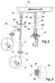
- the tube 1 shown in FIG. 1 is made, for example, of aluminum or a metallic alloy as an extruded part and serves as a gas generator for an impact bag used in vehicle construction for personal safety. If necessary, this is inflated by igniting a pyrotechnic charge at the head 2 of the tube 1, the gas generated exiting the tube 1 through a plurality of bores 3 in the tube wall.
- the holes 3 are located in two opposite segments 4 extending in the direction of the tube axis come into contact, the bores 3 are covered with, for example self-adhesive, preferably metallic foil strips 5 which are introduced inside the tube. This film is destroyed by the explosion pressure in the area of the holes, so that the gas generated can escape.
- the segments 4 are laterally delimited by ribs 6 formed on the inner tube wall, which extend over the entire length of the tube. Between each pair of ribs 6, a hinted metallic screen 7 is introduced, which covers the respective film strips 5. This prevents solid particles from getting through the holes 3 into the impact bag when the propellant charge explodes.
- the assembly system for introducing the film strips 5 into the tube 1 is described below in connection with FIG.
- the film is a metallic, endless band 8, one side of which is provided with an adhesive layer which is covered by a band film made of plastic.
- the tape 8 is unwound from a roll 9 and passes through a pair of forming rolls 10, so that the tape 8 receives a curvature which is adapted to the inside diameter of the tube and the adhesive layer is the convex side of the tape.
- the belt 8 then passes through a forming station 11, which is formed from a fixed jaw and a jaw that is movable perpendicularly to it, the latter being pressed against the fixed jaw each time the belt is at a standstill and pressing the curvature introduced into the belt 8.
- the tape film covering the adhesive layer of the tape is pulled off the metallic film and wound onto a roll 12.
- a carriage 14 with two tool heads 15, 16 which can be displaced horizontally in two positions is arranged on a gallows 13.
- the heads 15, 16 can each be positioned over a workpiece carrier 17 in which the tube 1 is clamped vertically.
- the workpiece carrier 17 is designed so that the tube 1 can be rotated through 180 ° about its vertical axis.
- the tool heads carry an intermediate carrier 18 designed as an expanding mandrel and a pressure expanding mandrel 19. The heads can be moved vertically by their heads and thus get into their respective working position.
- the intermediate carrier 18 is displaced vertically into the position shown in dashed lines.
- the outer contour of the intermediate carrier 18 has a contour corresponding to the curvature of the film strip 5 in the area which can be brought into contact with the film strip 5.
- the intermediate carrier is designed as an expanding mandrel.
- the segment 19 which extends axially parallel to the circumference forms the receptacle for the film strip 5.
- the segment 19 can have a smooth layer of rubber or plastic.
- the film strip 5 is sucked onto the segment by means of negative pressure through a large number of bores 20 in the segment 19.
- the intermediate carrier moves back from the takeover position shown in dashed lines to the starting position shown with full lines and the film strip 5 is separated from the belt 8 by means of a separating device 27.
- the tape unwinding is stopped and the intermediate carrier 18 is moved horizontally by means of the slide 14 into a position above the tube 1 clamped in the workpiece carrier 17, this position being in a fictitious Extension of the tube axis is located and tube 1 and intermediate support 18 are assigned to one another in such a way that the metallic foil strip located on the intermediate support is located in the fictitious extension of one of the segment 4 of the tube 1 having the bores 3.
- the intermediate carrier 18 designed as an expanding mandrel moves into the tube 1 by a predetermined amount and the segment 19 is extended at a right angle by a predetermined amount parallel to the tube axis, so that the metallic film strip 5 is brought into contact and glued to the tube inner wall by means of the adhesive layer.
- the intermediate carrier 18 After switching off the negative pressure and resetting the extended segment 19, the intermediate carrier 18 is moved out of the tube 1 and the carriage 14 returns it to the receiving position.
- the workpiece carrier 17 switches through 180 ° and, by repeating the procedure described, a second film strip 5 is introduced into the tube.
- the tool head 16 has a pressure expanding mandrel 21. This has two opposing legs 22, one end of which is clamped in the tool head 16 and the distance between the free ends can be varied by means of a mandrel 24 which can be inserted between cams 23 located on the inside of the legs 22.
- the free ends carry end pieces 25 adapted to the inside diameter of the tube in a width which corresponds to the clear distance between a pair of ribs 6.
- the pressing mandrel 21 is inserted into the tube so that the end pieces 25 are in the path of the film strips 5.
- the legs 22 are spread out like a scissors by the mandrel 24 and pulled out in a spread state, whereby by means of the end pieces 25, the metallic foils 5 are pressed practically progressively in a flexing process against the inner wall of the tube, thereby ensuring a bubble-free adhesive connection.
- the end pieces 25 are suitably geometrically shaped and have, for example, a run-on surface 26 formed by a rounding.
Landscapes
- Engineering & Computer Science (AREA)
- Mechanical Engineering (AREA)
- Physics & Mathematics (AREA)
- Fluid Mechanics (AREA)
- Making Paper Articles (AREA)
Applications Claiming Priority (2)
| Application Number | Priority Date | Filing Date | Title |
|---|---|---|---|
| DE1995126348 DE19526348C1 (de) | 1995-07-19 | 1995-07-19 | Verfahren und Vorrichtung zur Anpressung von geklebten Folienstreifen |
| DE19526348 | 1995-07-19 |
Publications (2)
| Publication Number | Publication Date |
|---|---|
| EP0755748A2 true EP0755748A2 (fr) | 1997-01-29 |
| EP0755748A3 EP0755748A3 (fr) | 1997-02-05 |
Family
ID=7767237
Family Applications (1)
| Application Number | Title | Priority Date | Filing Date |
|---|---|---|---|
| EP96109736A Withdrawn EP0755748A3 (fr) | 1995-07-19 | 1996-06-18 | Procédé et dispositif pour presser des bandes des feuilles collée |
Country Status (2)
| Country | Link |
|---|---|
| EP (1) | EP0755748A3 (fr) |
| DE (1) | DE19526348C1 (fr) |
Cited By (2)
| Publication number | Priority date | Publication date | Assignee | Title |
|---|---|---|---|---|
| EP1123845A3 (fr) * | 2000-02-11 | 2003-01-02 | TRW Airbag Systems GmbH & Co. KG | Générateur de gaz |
| CN118372012A (zh) * | 2024-06-24 | 2024-07-23 | 常州市德威盛汽车部件有限公司 | 一种减震器生产用弹簧压装机构及其压装方法 |
Family Cites Families (10)
| Publication number | Priority date | Publication date | Assignee | Title |
|---|---|---|---|---|
| US4397596A (en) * | 1980-12-29 | 1983-08-09 | Ford Motor Company | Method of making container for gas generating propellant |
| JPS5820331A (ja) * | 1981-07-28 | 1983-02-05 | Isamu Tagami | パイプ拡張機 |
| FR2528336B1 (fr) * | 1982-06-15 | 1986-03-07 | Allinquant J G | Procede d'assemblage de pieces tubulaires concentriques, particulierement applicable a l'assemblage de tubes d'amortisseurs avec leurs ferrures de fixation et pieces tubulaires ainsi assemblees |
| US4783228A (en) * | 1986-07-03 | 1988-11-08 | Lockheed Corporation | Method of bonding metal skins to internal support structures |
| US4779445A (en) * | 1987-09-24 | 1988-10-25 | Foster Wheeler Energy Corporation | Sleeve to tube expander device |
| DE3900671C1 (en) * | 1989-01-12 | 1990-03-08 | Messerschmitt-Boelkow-Blohm Gmbh, 8012 Ottobrunn, De | Process for securing the position of a metal insert in a plastic wall |
| GB8901742D0 (en) * | 1989-01-26 | 1989-03-15 | British Aerospace | Adhesive bonding of structures |
| DE4004819C1 (fr) * | 1990-02-16 | 1991-08-08 | Claus 7120 Bietigheim-Bissingen De Schmidt | |
| DE4232627A1 (de) * | 1992-09-29 | 1993-04-22 | Zacher Karl Heinz | Spreizspannfutter zum innenspannen und stuetzen von hohlkoerpern |
| DE4324554B4 (de) * | 1993-07-22 | 2006-03-02 | Delphi Technologies, Inc. (n.d.Ges.d. Staates Delaware), Troy | Gasgenerator, insbesondere für einen Airbag |
-
1995
- 1995-07-19 DE DE1995126348 patent/DE19526348C1/de not_active Expired - Fee Related
-
1996
- 1996-06-18 EP EP96109736A patent/EP0755748A3/fr not_active Withdrawn
Cited By (3)
| Publication number | Priority date | Publication date | Assignee | Title |
|---|---|---|---|---|
| EP1123845A3 (fr) * | 2000-02-11 | 2003-01-02 | TRW Airbag Systems GmbH & Co. KG | Générateur de gaz |
| US6626115B2 (en) | 2000-02-11 | 2003-09-30 | Trw Airbag Systems Gmbh & Co. Kg | Gas generator |
| CN118372012A (zh) * | 2024-06-24 | 2024-07-23 | 常州市德威盛汽车部件有限公司 | 一种减震器生产用弹簧压装机构及其压装方法 |
Also Published As
| Publication number | Publication date |
|---|---|
| DE19526348C1 (de) | 1997-02-06 |
| EP0755748A3 (fr) | 1997-02-05 |
Similar Documents
| Publication | Publication Date | Title |
|---|---|---|
| DE102014006576A1 (de) | Verfahren zum Zusammenlegen eines Gassackes, Gassack gefaltet gemäß einem derartigen Verfahren, Gassack, Gassackmodul und Fahrzeugsicherheitssystem | |
| WO1998022311A1 (fr) | Sac a gaz pour un module airbag, et procede et dispositif de pliage d'un sac a gaz | |
| EP0712760A1 (fr) | Procédé de pliage d'un coussin d'air pour système de retenue pour occupants de véhicule, dispositif pour l'exécution de ce procédé et coussin d'air ainsi obtenu | |
| DE19526348C1 (de) | Verfahren und Vorrichtung zur Anpressung von geklebten Folienstreifen | |
| EP1749590B1 (fr) | Procédé d'application d'adhésifs sur une liaison entre deux bandes et applicateur de ruban adhésif | |
| EP1179455B9 (fr) | Méthode de pliage d'un coussin de sécurité et dispositif de mise en oeuvre de cette méthode | |
| EP0853026B1 (fr) | Sac de sécurité gonflable pour un systèm de retenue des occupants ainsi qu'un procédé et un dispositif pour le pliage d'un tel sac | |
| DE2142979C3 (de) | Vorrichtung zum Abtrennen und Zerkleinern des Gummis eines Kraftfahrzeugreifens mit Stahldrahtverstärkung seinlage | |
| DE10338170B4 (de) | Rollfalzvorrichtung und deren Verwendung | |
| DE1761403A1 (de) | Verpackungsmaterial,insbesondere fuer Saecke,sowie Verfahren und Einrichtung zu seiner Herstellung | |
| DE202004003737U1 (de) | Vorrichtung zum dreidimensionalen Schneiden von Bauteilen | |
| DE10035236A1 (de) | Abklebewerkzeuge und Verfahren zum automatisierten, serienmäßigen Applizieren von Klebeband | |
| DE2544633A1 (de) | Schnittvorrichtung fuer kunststoffrohre | |
| DE19526347C1 (de) | Vorrichtung zum Befestigen mindestens eines metallischen, geflochtenen Siebes | |
| DE102004039577B3 (de) | Vorrichtung zum Herstellen von Rohren | |
| EP1526045B1 (fr) | Procédé de production d'une enveloppe pour un module de coussin gonflable | |
| EP3995287A1 (fr) | Procédé et dispositif pour fixer des applications à un tuyau | |
| DE2123628A1 (de) | Verfahren und Vorrichtung zum Aufblasen langer Längen aus zusammengesetzten Metallstreifen | |
| EP0234505B1 (fr) | Appareil et procédé pour appliquer un adhésif sur des profilés élastiques | |
| DE102011016676B4 (de) | Verfahren zur Herstellung eines kompakten Gassackpakets sowie Gassackmodul mit einem derart hergestellten Gassackpaket | |
| DE2243293C2 (de) | Vorrichtung zum Biegen von strangförmigen Werkstücken | |
| DE2738862C2 (de) | Verfahren zur Herstellung von dünnwandigen Zweikanalrohren | |
| DE3740750A1 (de) | Verfahren und vorrichtung zur herstellung von regenfallrohren | |
| DE2110316C3 (de) | Verfahren und Vorrichtung zum Lochen einer Platte zum Herstellen von Siebplatten aus Gummi oder gummielastischem Kunststoff | |
| DE3821787A1 (de) | Verfahren und einrichtung zur herstellung eines rohrbogens |
Legal Events
| Date | Code | Title | Description |
|---|---|---|---|
| PUAI | Public reference made under article 153(3) epc to a published international application that has entered the european phase |
Free format text: ORIGINAL CODE: 0009012 |
|
| PUAL | Search report despatched |
Free format text: ORIGINAL CODE: 0009013 |
|
| AK | Designated contracting states |
Kind code of ref document: A2 Designated state(s): DE FR GB IT |
|
| AK | Designated contracting states |
Kind code of ref document: A3 Designated state(s): DE FR GB IT |
|
| 17P | Request for examination filed |
Effective date: 19970206 |
|
| STAA | Information on the status of an ep patent application or granted ep patent |
Free format text: STATUS: THE APPLICATION HAS BEEN WITHDRAWN |
|
| 18W | Application withdrawn |
Withdrawal date: 19980808 |