EP0756093A1 - Befestigungselement mit Dämpfungselement - Google Patents
Befestigungselement mit Dämpfungselement Download PDFInfo
- Publication number
- EP0756093A1 EP0756093A1 EP96810387A EP96810387A EP0756093A1 EP 0756093 A1 EP0756093 A1 EP 0756093A1 EP 96810387 A EP96810387 A EP 96810387A EP 96810387 A EP96810387 A EP 96810387A EP 0756093 A1 EP0756093 A1 EP 0756093A1
- Authority
- EP
- European Patent Office
- Prior art keywords
- sleeve
- bolt
- shaft
- damping element
- head
- Prior art date
- Legal status (The legal status is an assumption and is not a legal conclusion. Google has not performed a legal analysis and makes no representation as to the accuracy of the status listed.)
- Granted
Links
- 238000013016 damping Methods 0.000 title claims description 36
- 230000002745 absorbent Effects 0.000 abstract 2
- 239000002250 absorbent Substances 0.000 abstract 2
- 230000035939 shock Effects 0.000 abstract 2
- 239000000463 material Substances 0.000 description 3
- 239000004567 concrete Substances 0.000 description 1
- 239000002184 metal Substances 0.000 description 1
- 238000000034 method Methods 0.000 description 1
- 239000004575 stone Substances 0.000 description 1
- 239000000758 substrate Substances 0.000 description 1
Images

Classifications
-
- F—MECHANICAL ENGINEERING; LIGHTING; HEATING; WEAPONS; BLASTING
- F16—ENGINEERING ELEMENTS AND UNITS; GENERAL MEASURES FOR PRODUCING AND MAINTAINING EFFECTIVE FUNCTIONING OF MACHINES OR INSTALLATIONS; THERMAL INSULATION IN GENERAL
- F16B—DEVICES FOR FASTENING OR SECURING CONSTRUCTIONAL ELEMENTS OR MACHINE PARTS TOGETHER, e.g. NAILS, BOLTS, CIRCLIPS, CLAMPS, CLIPS OR WEDGES; JOINTS OR JOINTING
- F16B19/00—Bolts without screw-thread; Pins, including deformable elements; Rivets
- F16B19/14—Bolts or the like for shooting into concrete constructions, metal walls or the like by means of detonation-operated nailing tools
Definitions
- the invention relates to a fastening element with a bolt having a head which can be driven into a subsurface by means of a powder-operated bolt-setting device, a sleeve with an external thread being arranged on a shaft of the bolt and the shaft at least partially in the area surrounded by the sleeve with a Surface profiling is provided.
- Fastening elements of the type under discussion are driven into surfaces consisting of hard materials such as concrete, stone, metal and the like by means of powder-operated bolt setting devices.
- the fastening elements serve as connection elements for parts that have to be fastened to these substrates.
- a fastening element with a bolt having a head which can be driven into a subsurface by means of a powder-operated bolt-setting device, a sleeve with an external thread being guided on a shaft of the bolt and the shaft having a surface profile.
- a press fit connection is achieved between a central passage opening of the sleeve and the surface profiling of the shaft.
- the part to be fastened can be screwed onto the external thread of the sleeve or fixed by means of a nut. High loads due to high, shock-like tensile forces that act on the fastening element can lead to failure of the fastening.
- the invention has for its object to provide a fastener which is able to prevent jerky tensile forces acting on the bolt.
- the object is achieved in that a damping element is arranged between the sleeve and the head of the bolt.
- the damping element is expediently sleeve-shaped.
- the sleeve and the damping element are advantageously formed in one piece.
- the sleeve on the bolt does not twist when a part is fastened to the fastener set and thus part of the tensile forces acting on the sleeve can be transmitted to the shaft of the bolt
- the sleeve is expediently press-fitted to the shaft of the bolt connected.
- the tensile forces acting on the external thread of the sleeve are thus transmitted on the one hand to the shaft of the bolt via the press fit connection and on the other hand to the head of the bolt via the damping element.
- the surface profile on the shaft of the bolt is designed in particular as a border.
- the sleeve moves on the shaft in spite of the press fit connection in the direction of the head of the bolt.
- the damping element deforms parallel to the longitudinal direction of the bolt. If the damping element is deformed in such a way that it is no longer able to transmit the shock-like tensile forces occurring to the head of the bolt, the bolt breaks or the bolt loosens in the ground.
- Fastening elements in which the tensile forces acting on the sleeve are transmitted entirely from the damping element to the head of the bolt, can be designed in such a way that they separate the sleeve and the part attached to it from the bolt when a certain tensile force is exceeded.
- the sleeve expediently has an internal diameter which is larger than the head of the bolt.
- a rotationally fixed connection between the sleeve and the bolt can be achieved in the case of fastening elements in which the tensile forces acting on the sleeve are entirely transmitted from the damping element to the head of the bolt
- a non-rotatable connection between the sleeve and the shaft of the bolt Shaft of the bolt connected clamping sleeve is arranged with an outer profile, which cooperates with an inner profile of the sleeve in a rotationally locking manner.
- the outer and inner profiles can be freely axially offset from one another.
- the clamping sleeve is advantageously connected to the shaft of the bolt in a rotationally fixed manner by means of a press fit.
- the external diameter of the damping element is preferably smaller than the core diameter of the external thread of the sleeve.
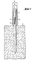
- the fastening element shown in FIG. 1, which is fixed in a subsurface U, is composed of a bolt 1 which has a tip 3 at a setting end on the setting direction and a head 2 at the opposite second end.
- the shaft 8 of the bolt 1 is provided with a surface profile 4 that extends partially over the shaft 8.
- a sleeve 5 is arranged, which is connected to the shaft 8 of the bolt 1 by means of a press fit connection.
- An external thread 6 is arranged on the outside of the sleeve 5.
- a damping element 7 is arranged between the sleeve 5 and the head 2 of the bolt 1.
- the outer diameter D of the damping element 7 is smaller than the core diameter K of the external thread 6, so that a part to be fastened, not shown, can be screwed on or fixed, for example, with the aid of a nut.
- the total length of the sleeve 5 and the damping element 7 is less than the length of the bolt 1.
- the tensile forces acting on the sleeve 5 of the fastener set are transmitted on the one hand via the press fit connection to the shaft 8 of the bolt 1 and on the other hand via the damping element 7 to the head 2 of the bolt 1.
- the damping element 7 deforms in the longitudinal direction until it no longer has damping properties. Subsequent high tensile forces lead to a failure of the bolt 1 by breaking or loosening in the ground.
- the damping element 7 can be made of a material that differs in hardness and elasticity from the material from which the sleeve 5 is made.
- the fastening element shown in FIG. 2, which is fixed in a subsurface U, is composed of a bolt 11 which has a tip 13 at a setting end on the setting direction and a head 12 at the opposite second end.
- the shaft 18 of the bolt 11 is provided with a surface profile 14 which extends partially over the shaft 18.
- a clamping sleeve 19 is arranged, which is connected to the shaft 18 of the bolt 11 by means of a press fit connection.
- the clamping sleeve 19 has an outer profile 21 which runs parallel to the longitudinal extent of the bolt 11 and which cooperates with a corresponding inner profile 20 which is arranged in a passage opening of a sleeve 15 with an external thread 16.
- the outer profile 21 of the clamping sleeve 19 and the inner profile 20 of the sleeve 15 are freely displaceable in the longitudinal direction of the bolt 11 and connected to one another in a rotationally fixed manner.
- a damping element 17 is arranged, which is formed in one piece with the sleeve 15.
- the outer diameter D of the damping element 17 is larger than the outer diameter of the head 12 of the bolt 11 and smaller than the core diameter K of the external thread 16, so that a part to be fastened, not shown, can be screwed on or, for example, fixed to the sleeve 15 with the aid of a nut.
- the total length of sleeve 15 and damping element 17 is less than the length of the bolt 11.
- the impact-like tensile forces acting on the sleeve 15 of the fastener set are transmitted to the head 12 of the bolt 11 via the damping element 17.
- the damping element 17 has the function of transmitting shock-like, high tensile forces to the bolt 11 in a damped manner.
- the damping element 17 deforms in the axial longitudinal direction. If it cannot be deformed further axially, it expands radially at subsequent high, shock-like tensile forces until it and the entire sleeve 15 can slide over the head 12 of the bolt 11.
Landscapes
- Engineering & Computer Science (AREA)
- General Engineering & Computer Science (AREA)
- Mechanical Engineering (AREA)
- Joining Of Building Structures In Genera (AREA)
- Dowels (AREA)
- Vibration Dampers (AREA)
Abstract
Description
- Die Erfindung betrifft ein Befestigungselement mit einem, einen Kopf aufweisenden Bolzen, der mittels eines pulverkraftbetriebenen Bolzensetzgerätes in einen Untergrund eintreibbar ist, wobei auf einem Schaft des Bolzens eine Hülse mit Aussengewinde angeordnet ist und der Schaft wenigstens teilweise in dem von der Hülse umgebenden Bereich mit einer Oberflächenprofilierung versehen ist.
- Befestigungselemente der hier zur Diskussion stehenden Art werden mittels pulverkraftbetriebener Bolzensetzgeräte in Untergründe, die aus harten Werkstoffen wie Beton, Gestein, Metall und dergleichen bestehen, eingetrieben. Die Befestigungselemente dienen als Anschlusselemente für Teile, die an diesen Untergründen befestigt werden müssen.
- Aus der US-PS 3,041,616 ist ein Befestigungselement mit einem, einen Kopf aufweisenden Bolzen bekannt, der mittels eines pulverkraftbetriebenen Bolzensetzgerätes in einen Untergrund eintreibbar ist, wobei auf einem Schaft des Bolzens eine Hülse mit Aussengewinde geführt ist und der Schaft eine Oberflächenprofilierung aufweist. Beim Setzvorgang des Bolzens wird eine Presssitzverbindung zwischen einer zentralen Durchtrittsöffnung der Hülse und der Oberflächenprofilierung des Schaftes erreicht. Auf das Aussengewinde der Hülse ist das zu befestigende Teil aufschraubbar oder mittels einer Mutter festlegbar. Hohe Belastungen aufgrund hoher, stossartiger Zugkräfte, die auf das Befestigungselement einwirken, können zu einem Versagen der Befestigung führen.
- Der Erfindung liegt die Aufgabe zugrunde, ein Befestigungselement zu schaffen, das in der Lage ist, stossartige, auf den Bolzen wirkende Zugkräfte zu verhindem.
- Erfindungsgemäss wird die Aufgabe dadurch gelöst, dass zwischen der Hülse und dem Kopf des Bolzens ein Dämpfungselement angeordnet ist.
- Die an der Hülse angreifenden Zugkräfte werden aufgrund des erfindungsgemäss angeordneten Dämpfungselementes nicht stossartig, sondern gedämpft auf den Kopf des Bolzens übertragen.
- Damit die an der Hülse angreifenden Zugkräfte gleichmässig auf den Kopf des Bolzens übertragen werden, ist das Dämpfungselement zweckmässigerweise hülsenförmig ausgebildet.
- Aus herstelltechnischen und wirtschaftlichen Gründen sind die Hülse und das Dämpfungselement vorteilhafterweise einstückig ausgebildet.
- Damit sich die Hülse auf dem Bolzen nicht verdreht, wenn ein Teil an dem gesetzten Befestigungselement befestigt wird und damit ein Teil der an der Hülse angreifenden Zugkräfte auf den Schaft des Bolzens übertragen werden kann, ist die Hülse zweckmässigerweise mittels eines Presssitzes mit dem Schaft des Bolzens verbunden. Die auf das Aussengewinde der Hülse wirkenden Zugkräfte werden somit einerseits über die Presssitzverbindung auf den Schaft des Bolzens, andererseits über das Dämpfungselement auf den Kopf des Bolzens übertragen. Die Oberflächenprofilierung am Schaft des Bolzens ist insbesondere als Randrierung ausgebildet.
- Bei Überschreiten einer bestimmten Zugkraft verschiebt sich die Hülse auf dem Schaft trotz der Presssitzverbindung in Richtung Kopf des Bolzens. Dabei verformt sich das Dämpfungselement parallel zur Längsrichtung des Bolzens. lst das Dämpfungselement derart verformt, dass es nicht mehr in der Lage ist, auftretende, stossartige Zugkräfte gedämpft auf den Kopf des Bolzen zu übertragen, so erfolgt ein Bruch des Bolzens oder ein Lösen des Bolzens im Untergrund.
- Befestigungselemente, bei denen die an der Hülse angreifenden Zugkräfte zur Gänze vom Dämpfungselement auf den Kopf des Bolzens übertragen werden, können so ausgebildet sein, dass sic die Hülse und das daran befestigte Teil beim Überschreiten einer bestimmten Zugkraft vom Bolzen trennen. Dabei weist zweckmässigerweise die Hülse einen lnnendurchmesser auf, der grösser ist als der Kopf des Bolzens.
- Auftretende, stossartige Zugkräfte werden unter einer axialen, parallel zur Längsachse des Bolzens stattfindenden Verformung des Dämpfungselementes gedämpft auf den Kopf des Bolzens übertragen. Nachdem keine weitere axiale Verformung des Dämpfungselementes mehr möglich ist, verformt sich das Dämpfungselement in radialer Richtung. Das Dämpfungselement weitet sich dabei so weit auf, bis es über den Kopf des Bolzens rutschen kann. Über die Dimensionierung des Dämpfungselementes ist somit die Versagenslast des Befestigungselementes einstellbar. Der Aussendurchmesser des einstückig mit der Hülse ausgebildeten Dämpfungselementes kann grösser sein als der Aussendurchmesser des Kopfes.
- Damit eine drehfeste Verbindung zwischen der Hülse und dem Bolzen bei Befestigungselementen erreicht werden kann, bei denen die an der Hülse angreifenden Zugkräfte zur Gänze vom Dämpfungselement auf den Kopf des Bolzens übertragen werden, ist zweckmässigerweise zwischen der Hülse und dem Schaft des Bolzens eine drehfest mit dem Schaft des Bolzens verbundene Klemmhülse mit einer Aussenprofilierung angeordnet, die mit einer Innenprofilierung der Hülse drehschlüssig zusammenwirkt. Die Aussen- und Innenprofilierung ist axial frei zueinander versetzbar. Die axiale Verformung des Dämpfungselementes beim Auftreten hoher, stossartiger Zugkräfte wird daher nicht beeinflusst und die drehschlüssige Verbindung gegenüber dem Schaft des Bolzens bleibt erhalten, bis sich das Dämpfungselement aufgrund der stossartigen Zugkräfte radial aufweitet und zusammen mit der Hülse vom Bolzen rutscht.
- Aus fertigungstechnischen und wirtschaftlichen Gründen ist vorteilhafterweise die Klemmhülse mittels eines Presssitzes mit dem Schaft des Bolzens drehfest verbunden.
- Damit das zu befestigende Teil mit dem Aussengewinde der Hülse in Verbindung gebracht werden kann, ist vorzugsweise der Aussendurchmesser des Dämpfungselementes kleiner als der Kemdurchmesser des Aussengewindes der Hülse.
- Die Erfindung wird anhand von Figuren, die zwei Ausführungsbeispiele zeigen, näher erläutert. Es zeigen:
- Fig.1
- ein erfindungsgemässes Befestigungselement, in geschnittener Darstellung und
- Fig. 2
- ein weiteres Befestigungselement, in geschnittener Darstellung.
- Das in Fig.1 dargestellte, in einem Untergrund U festgelegte Befestigungselement setzt sich zusammen aus einem Bolzen 1, der an einem setzrichtungsseitigen ersten Ende eine Spitze 3 und am gegenüberliegenden zweiten Ende einen Kopf 2 aufweist. Der Schaft 8 des Bolzens 1 ist mit einer sich teilweise über den Schaft 8 erstreckenden Oberflächenprofilierung 4 versehen. Im Bereich dieser Oberflächenprofilierung 4 ist eine Hülse 5 angeordnet, die mittels eines Presssitzverbindung mit dem Schaft 8 des Bolzens 1 verbunden ist. Auf der Aussenseite der Hülse 5 ist ein Aussengewinde 6 angeordnet.
- Zwischen der Hülse 5 und dem Kopf 2 des Bolzens 1 ist ein Dämpfungselement 7 angeordnet. Der Aussendurchmesser D des Dämpfungselementes 7 ist kleiner als der Kemdurchmesser K des Aussengewindes 6, damit ein zu befestigendes, nicht dargestelltes Teil aufgeschraubt oder beispielsweise mit Hilfe einer Mutter festgelegt werden kann. Die Gesamtlänge von Hülse 5 und Dämpfungselement 7 ist kleiner als die Länge des Bolzens 1.
- Die an der Hülse 5 des gesetzten Befestigungselements angreifenden Zugkräfte werden einerseits über die Presssitzverbindung auf den Schaft 8 des Bolzens 1, andererseits über das Dämpfungselement 7 auf den Kopf 2 des Bolzens 1 übertragen. Beim Auftreten hoher Zugkräfte verformt sich das Dämpfungselement 7 in Längsrichtung, bis es keine Dämpfungseigenschaften mehr besitzt. Nachfolgend auftretende, hohe Zugkräfte führen zu einem Versagen des Bolzens 1, indem er bricht oder sich im Untergrund löst.
- Das Dämpfungselement 7 kann aus einem Material gefertigt sein, das in der Härte und Elastizität abweicht von dem Material aus dem die Hülse 5 besteht.
- Das in Fig. 2 dargestellte, in einem Untergrund U festgelegte Befestigungselement setzt sich zusammen aus einem Bolzen, 11 der an einem setzrichtungsseitigen ersten Ende eine Spitze 13 und am gegenüberliegenden zweiten Ende einen Kopf 12 aufweist. Der Schaft 18 des Bolzens 11 ist mit einer sich teilweise über den Schaft 18 erstreckenden Oberflächenprofilierung 14 versehen. Im Bereich dieser Oberflächenprofilierung 14 ist eine Klemmhülse 19 angeordnet, die mittels einer Presssitzverbindung mit dem Schaft 18 des Bolzens 11 in Verbindung steht. Die Klemmhülse 19 besitzt auf der Aussenseite eine parallel zur Längserstreckung des Bolzens 11 verlaufende Aussenprofilierung 21, die mit einer entsprechenden, in einer Durchtrittsöffnung einer Hülse 15 mit Aussengewinde 16 angeordneten Innenprofilierung 20 zusammenwirkt. Die Aussenprofilierung 21 der Klemmhülse 19 und die Innenprofilierung 20 der Hülse 15 sind in Längsrichtung des Bolzens 11 frei zueinander versetzbar und drehfest miteinander verbunden.
- Zwischen der Hülse 15 und dem Kopf 12 des Bolzens 11 ist ein Dämpfungselement 17 angeordnet, das einstückig mit der Hülse 15 ausgebildet ist. Der Aussendurchmesser D des Dämpfungselementes 17 ist grösser als der Aussendurchmesser des Kopfes 12 des Bolzens 11 und kleiner als der Kerndurchmesser K des Aussengewindes 16, damit ein zu befestigendes, nicht dargestelltes Teil aufgeschraubt oder beispielsweise mit Hilfe einer Mutter an der Hülse 15 festgelegt werden kann. Die Gesamtlänge von Hülse 15 und Dämpfungselement 17 ist kleiner als die Länge des Bolzens 11.
- Die an der Külse 15 des gesetzten Befestigungselements angreifenden, stossartigen Zugkräfte werden über das Dämpfungselement 17 auf den Kopf 12 des Bolzens 11 übertragen. Das Dämpfungselement 17 hat die Funktion, stossartige, hohe Zugkräfte gedämpft auf den Bolzen 11 zu übertragen. Dabei verformt sich das Dämpfungselement 17 in axialer Längsrichtung. Lässt es sich nicht weiter axial verformen, so weitet sich dieses bei nachfolgenden hohen, stossartigen Zugkräften radial auf, bis es und die ganze Hülse 15 über den Kopf 12 des Bolzens 11 rutschen können.
Claims (8)
- Befestigungselement mit einem einen Kopf (2, 12) aufweisenden Bolzen (1, 11), der mittels eines pulverkraftbetriebenen Bolzensetzgerätes in einen Untergrund eintreibbar ist, wobei auf einem Schaft (8, 18) des Bolzens (1, 11) eine Hülse (5, 15) mit Aussengewinde (6, 16) angeordnet ist und der Schaft (8, 18) wenigstens teilweise in dem von der Hülse (5, 15) umgebenen Bereich mit einer Oberflächenprofilierung (4, 14) versehen ist, dadurch gekennzeichnet, dass zwischen der Hülse (5, 15) und dem Kopf (2, 12) des Bolzens (1, 11) ein Dämpfungselement (7, 17) angeordnet ist.
- Befestigungselement nach Anspruch 1, dadurch gekennzeichnet, dass das Dämpfungselement (7, 17) hülsenförmig ausgebildet ist.
- Befestigungselement nach Anspruch 1 oder 2, dadurch gekennzeichnet, dass die Hülse (5, 15) und das Dämpfungselement (7, 17) einstückig ausgebildet sind.
- Befestigungselement nach einem der Ansprüche 1 bis 3, dadurch gekennzeichnet, dass die Hülse (5) mittels eines Presssitzes mit dem Schaft (8) des Bolzens (1) verbunden ist.
- Befestigungselement nach einem der Anprüche 1 bis 3, dadurch gekennzeichnet, dass die Hülse (15) einen Innendurchmesser aufweist, der grösser ist als der Durchmesser des Kopfes (12) des Bolzens (11).
- Befestigungselement nach Anspruch 5, dadurch gekennzeichnet, dass zwischen der Hülse (15) und dem Schaft (18) des Bolzens (11) eine drehfest mit dem Schaft (18) des Bolzens (11) verbundene Klemmhülse (19) mit einer Aussenprofilierung (21) angeordnet ist, die mit einer Innenprofilierung (20) der Hülse (15) drehschlüssig zusammenwirkt
- Befestigungselement nach Anspruch 6, dadurch gekennzeichnet, dass die Klemmhülse (19) mittels eines Presssitzes mit dem Schaft (18) des Bolzens (11) verbunden ist.
- Befestigungselement nach einem der Ansprüche 1 bis 7, dadurch gekennzeichnet, dass der Aussendurchmesser (D) des Dämpfungselementes (7, 17) kleiner ist als der Kemdurchmesser (K) des Aussengewindes (6, 16) der Hülse (5, 15).
Applications Claiming Priority (2)
| Application Number | Priority Date | Filing Date | Title |
|---|---|---|---|
| DE19527469 | 1995-07-28 | ||
| DE19527469A DE19527469A1 (de) | 1995-07-28 | 1995-07-28 | Befestigungselement mit Dämpfungselement |
Publications (2)
| Publication Number | Publication Date |
|---|---|
| EP0756093A1 true EP0756093A1 (de) | 1997-01-29 |
| EP0756093B1 EP0756093B1 (de) | 1999-10-13 |
Family
ID=7767938
Family Applications (1)
| Application Number | Title | Priority Date | Filing Date |
|---|---|---|---|
| EP96810387A Expired - Lifetime EP0756093B1 (de) | 1995-07-28 | 1996-06-12 | Befestigungselement mit Dämpfungselement |
Country Status (3)
| Country | Link |
|---|---|
| EP (1) | EP0756093B1 (de) |
| AT (1) | ATE185612T1 (de) |
| DE (1) | DE19527469A1 (de) |
Cited By (1)
| Publication number | Priority date | Publication date | Assignee | Title |
|---|---|---|---|---|
| EP2182225A3 (de) * | 2008-11-04 | 2017-04-05 | HILTI Aktiengesellschaft | Gewindebolzen |
Citations (2)
| Publication number | Priority date | Publication date | Assignee | Title |
|---|---|---|---|---|
| US3041616A (en) * | 1954-02-17 | 1962-07-03 | Olin Mathieson | Fastening apparatus |
| EP0282445A1 (de) * | 1987-03-07 | 1988-09-14 | HILTI Aktiengesellschaft | Befestigungselement mit Nagel und Hülse |
-
1995
- 1995-07-28 DE DE19527469A patent/DE19527469A1/de not_active Withdrawn
-
1996
- 1996-06-12 EP EP96810387A patent/EP0756093B1/de not_active Expired - Lifetime
- 1996-06-12 AT AT96810387T patent/ATE185612T1/de not_active IP Right Cessation
Patent Citations (2)
| Publication number | Priority date | Publication date | Assignee | Title |
|---|---|---|---|---|
| US3041616A (en) * | 1954-02-17 | 1962-07-03 | Olin Mathieson | Fastening apparatus |
| EP0282445A1 (de) * | 1987-03-07 | 1988-09-14 | HILTI Aktiengesellschaft | Befestigungselement mit Nagel und Hülse |
Cited By (1)
| Publication number | Priority date | Publication date | Assignee | Title |
|---|---|---|---|---|
| EP2182225A3 (de) * | 2008-11-04 | 2017-04-05 | HILTI Aktiengesellschaft | Gewindebolzen |
Also Published As
| Publication number | Publication date |
|---|---|
| EP0756093B1 (de) | 1999-10-13 |
| DE19527469A1 (de) | 1997-01-30 |
| ATE185612T1 (de) | 1999-10-15 |
Similar Documents
| Publication | Publication Date | Title |
|---|---|---|
| EP0282445B1 (de) | Befestigungselement mit Nagel und Hülse | |
| EP1800807B1 (de) | Handgriff mit Vibrationsminderungseinrichtung | |
| DE10334906B4 (de) | Antivibrationselement | |
| EP0289729B1 (de) | Befestigungselement | |
| EP0499580B1 (de) | Ausziehwerkzeug | |
| EP0688965A1 (de) | Vorspannkontrollelement für Schraubanker | |
| EP1253332B1 (de) | Nagelförmiges Befestigungselement | |
| EP1233194B1 (de) | Betonschraube | |
| EP0420797A2 (de) | Anschlagkörper für Betonschalungen | |
| EP0905389A2 (de) | Betonschraube | |
| DE4143218C2 (de) | Vorrichtung zur Verbindung von Schraubendreher-Einsätzen | |
| EP0774589B1 (de) | Bolzen zum Eintreiben in harte Aufnahmewerkstoffe | |
| DE102004020000B4 (de) | Abhängeelement | |
| EP3346145A1 (de) | Vorrichtung zur drehmomentbegrenzung mit drei stegen | |
| EP0768151B1 (de) | Werkzeughalter | |
| DE10231840B3 (de) | Welle-Nabeverbindung | |
| EP3147079A1 (de) | Vorrichtung zur drehmomentbegrenzung | |
| EP0406801B1 (de) | Befestigungselement | |
| EP1013944A2 (de) | Befestigungselement | |
| EP0756093B1 (de) | Befestigungselement mit Dämpfungselement | |
| EP0470470A2 (de) | Dübel mit einer Dübelhülse | |
| EP0457249B1 (de) | Anhängerkupplung Stichwort: Verliersicherung mit Wackelabstand | |
| DE19912068B4 (de) | Wellen- oder Stellmutter und Verfahren zu ihrer Herstellung | |
| EP0995914B1 (de) | Befestigungselement aus Metall mit Innengewinde für die Durchsteckmontage | |
| EP1631733A1 (de) | Halteelement für ein rundschaftmeissel einer fräsvorrichtung |
Legal Events
| Date | Code | Title | Description |
|---|---|---|---|
| PUAI | Public reference made under article 153(3) epc to a published international application that has entered the european phase |
Free format text: ORIGINAL CODE: 0009012 |
|
| AK | Designated contracting states |
Kind code of ref document: A1 Designated state(s): AT CH FR LI SE |
|
| 17P | Request for examination filed |
Effective date: 19970211 |
|
| GRAG | Despatch of communication of intention to grant |
Free format text: ORIGINAL CODE: EPIDOS AGRA |
|
| GRAG | Despatch of communication of intention to grant |
Free format text: ORIGINAL CODE: EPIDOS AGRA |
|
| GRAH | Despatch of communication of intention to grant a patent |
Free format text: ORIGINAL CODE: EPIDOS IGRA |
|
| 17Q | First examination report despatched |
Effective date: 19990326 |
|
| GRAH | Despatch of communication of intention to grant a patent |
Free format text: ORIGINAL CODE: EPIDOS IGRA |
|
| GRAA | (expected) grant |
Free format text: ORIGINAL CODE: 0009210 |
|
| AK | Designated contracting states |
Kind code of ref document: B1 Designated state(s): AT CH FR LI SE |
|
| REF | Corresponds to: |
Ref document number: 185612 Country of ref document: AT Date of ref document: 19991015 Kind code of ref document: T |
|
| REG | Reference to a national code |
Ref country code: CH Ref legal event code: EP |
|
| ET | Fr: translation filed | ||
| PLBE | No opposition filed within time limit |
Free format text: ORIGINAL CODE: 0009261 |
|
| STAA | Information on the status of an ep patent application or granted ep patent |
Free format text: STATUS: NO OPPOSITION FILED WITHIN TIME LIMIT |
|
| 26N | No opposition filed | ||
| PGFP | Annual fee paid to national office [announced via postgrant information from national office to epo] |
Ref country code: SE Payment date: 20010417 Year of fee payment: 6 |
|
| PGFP | Annual fee paid to national office [announced via postgrant information from national office to epo] |
Ref country code: AT Payment date: 20010613 Year of fee payment: 6 |
|
| PGFP | Annual fee paid to national office [announced via postgrant information from national office to epo] |
Ref country code: CH Payment date: 20010615 Year of fee payment: 6 |
|
| PG25 | Lapsed in a contracting state [announced via postgrant information from national office to epo] |
Ref country code: AT Free format text: LAPSE BECAUSE OF NON-PAYMENT OF DUE FEES Effective date: 20020612 |
|
| PG25 | Lapsed in a contracting state [announced via postgrant information from national office to epo] |
Ref country code: SE Free format text: LAPSE BECAUSE OF NON-PAYMENT OF DUE FEES Effective date: 20020613 |
|
| PG25 | Lapsed in a contracting state [announced via postgrant information from national office to epo] |
Ref country code: LI Free format text: LAPSE BECAUSE OF NON-PAYMENT OF DUE FEES Effective date: 20020630 Ref country code: CH Free format text: LAPSE BECAUSE OF NON-PAYMENT OF DUE FEES Effective date: 20020630 |
|
| EUG | Se: european patent has lapsed | ||
| REG | Reference to a national code |
Ref country code: CH Ref legal event code: PL |
|
| PGFP | Annual fee paid to national office [announced via postgrant information from national office to epo] |
Ref country code: FR Payment date: 20120619 Year of fee payment: 17 |
|
| REG | Reference to a national code |
Ref country code: FR Ref legal event code: ST Effective date: 20140228 |
|
| PG25 | Lapsed in a contracting state [announced via postgrant information from national office to epo] |
Ref country code: FR Free format text: LAPSE BECAUSE OF NON-PAYMENT OF DUE FEES Effective date: 20130701 |