EP0756215A2 - Reinigungssystem für elektrostatographische Abbildungsbänder - Google Patents
Reinigungssystem für elektrostatographische Abbildungsbänder Download PDFInfo
- Publication number
- EP0756215A2 EP0756215A2 EP96305420A EP96305420A EP0756215A2 EP 0756215 A2 EP0756215 A2 EP 0756215A2 EP 96305420 A EP96305420 A EP 96305420A EP 96305420 A EP96305420 A EP 96305420A EP 0756215 A2 EP0756215 A2 EP 0756215A2
- Authority
- EP
- European Patent Office
- Prior art keywords
- contact
- roll
- web
- cleaner
- cleaning
- Prior art date
- Legal status (The legal status is an assumption and is not a legal conclusion. Google has not performed a legal analysis and makes no representation as to the accuracy of the status listed.)
- Withdrawn
Links
Images



Classifications
-
- G—PHYSICS
- G03—PHOTOGRAPHY; CINEMATOGRAPHY; ANALOGOUS TECHNIQUES USING WAVES OTHER THAN OPTICAL WAVES; ELECTROGRAPHY; HOLOGRAPHY
- G03G—ELECTROGRAPHY; ELECTROPHOTOGRAPHY; MAGNETOGRAPHY
- G03G21/00—Arrangements not provided for by groups G03G13/00 - G03G19/00, e.g. cleaning, elimination of residual charge
- G03G21/0005—Arrangements not provided for by groups G03G13/00 - G03G19/00, e.g. cleaning, elimination of residual charge for removing solid developer or debris from the electrographic recording medium
-
- B—PERFORMING OPERATIONS; TRANSPORTING
- B08—CLEANING
- B08B—CLEANING IN GENERAL; PREVENTION OF FOULING IN GENERAL
- B08B7/00—Cleaning by methods not provided for in a single other subclass or a single group in this subclass
- B08B7/0028—Cleaning by methods not provided for in a single other subclass or a single group in this subclass by adhesive surfaces
-
- G—PHYSICS
- G03—PHOTOGRAPHY; CINEMATOGRAPHY; ANALOGOUS TECHNIQUES USING WAVES OTHER THAN OPTICAL WAVES; ELECTROGRAPHY; HOLOGRAPHY
- G03G—ELECTROGRAPHY; ELECTROPHOTOGRAPHY; MAGNETOGRAPHY
- G03G21/00—Arrangements not provided for by groups G03G13/00 - G03G19/00, e.g. cleaning, elimination of residual charge
- G03G21/0005—Arrangements not provided for by groups G03G13/00 - G03G19/00, e.g. cleaning, elimination of residual charge for removing solid developer or debris from the electrographic recording medium
- G03G21/0058—Arrangements not provided for by groups G03G13/00 - G03G19/00, e.g. cleaning, elimination of residual charge for removing solid developer or debris from the electrographic recording medium using a roller or a polygonal rotating cleaning member; Details thereof, e.g. surface structure
Definitions
- This invention relates in general to an apparatus and process for cleaning electrostatographic imaging webs.
- the flexible belts are usually multilayered photoreceptors that comprise a substrate, a conductive layer, an optional hole blocking layer, an optional adhesive layer, a charge generating layer, and a charge transport layer and, in some embodiments, an anti-curl backing layer.
- particles of dirt residing on an uncoated or coated substrate surface during application of coatings to form an electrostatographic imaging member, such as a photoreceptor, can cause bubbles or voids to form in the various applied coating layers. It is believed that the dirt particles behave in a manner similar to a boiling chip which initiates solvent boiling at the location of the particle. This local boiling problem is aggravated when a coating solution is maintained near the boiling point of the coating solvent during deposition of the coating or during drying. The formation of bubbles in a coating is particularly acute in photoreceptor charge generation layer coatings and in charge transport layer coatings. Also, dirt particles tend to trap air during application of a coating and the trapped air expands during drying to form an undesirable bubble in the coating.
- any dirt particles residing on one or both major surfaces of an electrophotographic imaging member web substrate can adversely affect adjacent surfaces when the web is rolled up into a roll because the dirt particles cause impressions on the adjacent web surfaces. Because these undesirable impressions can be repeated through more than one overlapping web layer, large sections of a coated web must be scrapped. Where large belts, e.g. ten pitch belts, are to be fabricated, a 10 percent defect rate for one pitch can result in the discarding of 70 to 80 percent of the entire web because very large expanses of defect free surfaces are required for such large belts.
- the sources of the dirt particles include transporting systems, coating systems, drying systems, cooling slitting systems, winding systems, unwinding systems, debris from the electrophotographic imaging member web substrate itself, workers, and the like.
- any dirt particles present on the web surface tends to lift the coating layer and cause local coating voids.
- This also occurs with relatively thin adhesive layers between a charge blocking layer and a charge generation layer.
- the coated web substrate is rolled up into a roll and transported to another coating station. During unrolling or unwinding of the coated web, static electricity is generated as the outermost ply of the coated web is separated from the roll. This static electricity tends to attract dirt particles to the exposed surfaces of the web.
- US-A 5,251,348 discloses a contact cleaner roll cleaning system which includes a frame supporting the system relative to a moving web, a contact cleaner roll turret on the frame, and a roll cleaner on the frame.
- the turret supports two or more rotatable contact cleaner rolls, an active roll in rolling contact with the web, and an idle roll out of contact with the web for cleaning.
- the idle roll is kept rotating while it is idle and being cleaned.
- the turret is rotatable to sequentially put the cleaner rolls into and out of contact with the web.
- the roll cleaner includes an absorbent cleaning material mounted adjacent to the idle roll for placement against it and movement lengthwise along it to wipe it clean. Spindles advance the cleaning material between wipings of the idle roll, and a liquid delivery system keeps the cleaning material wet.
- US-A 5,275,104 discloses an apparatus for cleaning a rotating process roll including cleaning material supply and take-up rolls and a compliant touch roll, all mounted on a carriage adjacent to a process roll.
- Touch roll and cleaning material are movable by air cylinders into and out of contact with the process roll.
- the touch roll is rotatable in one direction only with the take-up roll.
- a drive motor winds the take-up roll to incrementally and uniformly advance the cleaning material over the touch roll.
- Period and frequency of the cleaning cycle and sub-cycles are variable by microprocessor control.
- Supply roll and take-up roll are supported in retractable gudgeons for easy mounting and removal.
- a contact cleaner roll cleaning system which includes a frame to support the system relative to a moving web having a first major surface and a second major surface, a first rotatable contact cleaner roll supported on the frame disposed for rolling contact with the first major surface of the web, a second rotatable contact cleaner roll supported on the frame disposed for rolling contact with the second major surface of the web, the second rotatable contact cleaner roll having an axis parallel to the axis of the first rotatable contact cleaner roll, the first contact cleaner roll and the second contact cleaner roll being positioned on the frame to support and guide the moving web in a substantially "S" shaped path.
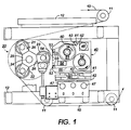
- FIG. 1 is a schematic end elevation view of a contact cleaner roll system, with obscuring end structure removed.
- FIG. 2 is a schematic front elevation view from the right of FIG. 1, with obscuring front structure removed.
- FIG. 3 is a schematic top view of FIG. 2, with obscuring top structure removed.
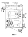
- FIG. 4 is a schematic front elevation view of a cleaning system embodiment of this invention in which a plurality of contact cleaner rolls support, clean and guide a moving web in a substantially "S" shaped path.
- FIG. 5 is a schematic front elevation view of the cleaning system embodiment shown in FIG. 4 utilized in combination with other web processing stations.
- FIG. 6 is a schematic front elevation view of another cleaning system embodiment of this invention in which a plurality of contact cleaner rolls support, clean and guide a moving web in a substantially "S" shaped path.
- FIG. 1 shows a contact cleaner roll system in a web processing apparatus.
- the web processing apparatus is indicated by a web 10 moving from left to right in a serpentine path over a series of rollers 11 on a frame 12.
- Web 10 has two major exposed surfaces.
- a contact cleaner roll turret 20, including contact cleaner rolls 21, 22, 23, is mounted on the frame 12 in the path of the web 10.
- the cleaner rolls 21, 22, 23 are steel rolls, coated with a polymer for a tacky surface.
- the tacky surfaces of the cleaner rolls in rolling contact with a major surface of the moving web 10, remove dirt particles of contamination from the major surface of web 10 as it rolls over the particles.
- the contact cleaner rolls in turn become contaminated and must be cleaned periodically to restore their effectiveness.
- a roll cleaner 40 is positioned adjacent to the contact cleaner roll turret 20 for movement into and out of engagement with it.
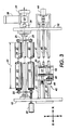
- FIGS. 2 and 3 are front and top views, further showing the relationship of the frame 12, the roll turret 20, and the contact cleaner rolls 21, 22, 23.
- the cleaner rolls 21, 22, 23 are of length L to span the full width W of the moving web 10 (L being greater than W).
- the cleaner roll turret 20 includes a rotatable turret shaft 24 extending from end to end of the frame 12, with an end plate 25 fixed to it at each end. Each end plate includes three radial arms 26, each supporting one end of a rotatable cleaner roll.
- the turret shaft 24 is connected through a suitable gear train 27 to a motor 28 and to a locking brake 29.
- the turret shaft 24 is positioned with two of its cleaner rolls 21, 22 active, in rolling contact with a major surface of the moving web 10 to clean the major surface.
- the third cleaner roll 23 is out of contact with the web 10, idle and out of service for its own cleaning.
- the motor 28 periodically rotates the turret 20 by the appropriate amount, 120° in this example, to take one cleaner roll out of service and to put another cleaner roll into service.
- a speed match drive motor 30 with a drive pinion 31 is mounted on the frame 12.
- Each of the cleaner rolls 21, 22, 23 has a drive gear 32 attached to it.
- the drive pinion 31 engages the drive gear 32 of the out-of-service cleaner roll (roll 23 in FIGS. 2 and 3).
- the drive motor 30 drives the out-of-service roll 23 and maintains its proper running speed to bring it back on line in rolling contact with the moving web 10. It is important to match the speed of the roll 23 with the speed of the web 10.
- the roll is tacky and adhesive, and if the speeds did not match, it would grab, disrupt, and even damage the moving web 10.
- the automatic roll cleaner 40 includes a subframe 41 mounted on a base plate 42 and movable relative to it in the Y direction (FIG.
- the base plate 42 is in turn mounted on the main frame 12 and is movable relative to it in the X direction, lengthwise along the idle cleaner roll 23.
- the roll cleaner 40 is thus movable relative to the main frame 12 in both X and Y directions in the horizontal plane.
- An air motor or cylinder 43 mounted on the base plate 42 moves the subframe 41 back and forth in the Y direction.
- a reversible stepper motor 44 mounted on the frame 12 moves the base plate 42, back and forth in the X direction, on slide rails 47 by a linear actuator 45, 46, analogous to a screw and nut.
- the portion of the main frame 12 supporting the roll cleaner 40 extends beyond the cleaner rolls 21, 22, 23 to provide a "home" position for the roll cleaner 40 when it is not in use or requires a cleaning cloth change.
- the cleaning head of the roll cleaner 40 includes a supply spindle 51 and a take-up spindle 52 for cleaning cloth 55, and a pair of guide bars 53 defining the path of the cleaning cloth 55 from the supply spindle 51 to the take-up spindle 52.
- a sponge pad 54 (see also FIG. 4) between the guide bars 53 abuts against the cleaning cloth 55.
- the sponge pad 54 is mounted on a concave backing plate 56 which includes a water inlet port 57 and internal ports leading from the inlet port 57 to the back of the sponge pad 54.
- a moisture sensor 58 is mounted on the backing plate 56, and in contact with the sponge pad 54 to detect moisture in the sponge pad. The moisture sensor 58 disables the system if the moisture level of the sponge pad is inadequate.
- the supply spindle 51 is initially full, and the take-up spindle 52 is initially empty of cleaning cloth 55.
- the take-up spindle is driven by a motor 48 and belt 49 to advance the cleaning cloth intermittently from the supply spindle 51 to the take-up spindle 52.
- the take-up spindle 52 pulls cloth from the supply spindle 51, over the guide bars 53, in the direction shown in FIG. 1.
- a no-cloth detector includes pivot arms 60 and 61 on a pivot axis 62.
- the first pivot arm 60 rests on the cloth 55 in the supply spindle 51.
- the second pivot arm 61 is movable from an open position, as shown, to a closed position in contact with a sensor 63 to signal a no-cloth condition and shut down the entire system.
- contact cleaner roll turrets 70 and 72 are shown mounted on the frame 12 in the path of the electrostatographic imaging web substrate 66.
- Contact cleaner roll turret 70 includes contact cleaner rolls 74, 76 and 78 and contact cleaner roll turret 72 includes contact cleaner rolls 80, 82 and 84.
- the components of contact cleaner roll turrets 70 and 72 are identical to the components of contact cleaner roll turret 20 described above.
- contact cleaner rolls 74, 76, 78, 80, 82 and 84 are steel rolls, coated with a polymer for a tacky surface.
- the contact cleaner roll turrets 70 and 72 are positioned on frame 12 so that contact cleaner rolls 74 and 76 contact a first major surface on one side of electrostatographic imaging web substrate 66 and contact cleaner rolls 80 and 82 contact a second major surface on the side of electrostatographic imaging web substrate 66 opposite the first major surface.
- the contact cleaner roll turrets 70 and 72 are also positioned on frame 12 to support and guide moving electrostatographic imaging web substrate 66 in a substantially "S" shaped path to clean both sides of web substrate 66 in an extremely short and compact path with contact between the web substrate 86 and the contact cleaner rolls being under substantially the same pressure for more uniform cleaning results.
- the lateral orientation of the rollers can be adjusted to vary the wrap angle, thus providing optimal cleaning.
- Idler roll 86 feeds electrostatographic imaging web substrate 66 to turret 70 and idler rolls 88, 90 and 92 guide web substrate 66 away from turret 72 to a take up roll or another processing station (not shown).
- electrostatographic imaging web substrate as employed herein is intended to include an uncoated or coated substrate component of an electrostatographic imaging member such as, for example, a film coated with a conductive layer, a film coated with a conductive layer and a charge blocking layer, and the like.
- FIG. 5 Shown in FIG. 5 is a coating subsystem utilizing the plurality of contact cleaner roll turrets 70 and 72 illustrated in FIG. 4. More specifically, electrostatographic imaging web substrate 66 is fed from a supply roll or another processing station (not shown) over idler roll 94 into coating station 96 where a coating is applied. After application of a coating, electrostatographic imaging web substrate 66 is then fed over idler rolls 98 and 100 into drying station 102. Subsequent to drying in drying station 102, web substrate 66 travels around idler rolls 104, 106, 108 and through air knife/vacuum station 110 for removal of large dirt particles having an average size greater than about 30 to 100 micrometers.
- the minimum particle size that can be removed from web substrate 66 by a non contacting cleaning station varies with the specific type of non contacting cleaning system selected and can be as low as about 30 micrometers with some non contacting cleaning systems being incapable of removing particles having an average size less than about 100 micrometers.
- Web substrate 66 then travels around chill rolls 112 and 114, around idler roll 116 and idler roll 86 to contact cleaner roll turrets 70 and 72, the roll turrets being shown in greater detail in FIG. 4.
- a reciprocatable nip roll assembly 117 comprising a nip roll, pivot arm and two way acting air cylinder, may be employed to ensure more uniform contact between chill roll 114 and web substrate 66.
- Coating station 96 may comprise any suitable and conventional coating station such as a gravure applicator system which applies a charge blocking layer, an extrusion applicator system which applies a charge generating layer or charge transport layer, or any other suitable coating system.
- Drying station 102 may comprise any suitable non-contact drying system such as a conventional oven, a forced air oven, a radiant heater, steam heater, electric heater, microwave, and the like. The preferred embodiment uses a floatable oven convention.
- FIG. 6 An alternative to the multiple contact cleaner roll turrets 70 and 72 shown in FIGs. 4 and 5, is the use of multiple single contact cleaner rolls 120 and 122 illustrated in FIG. 6.
- single contact cleaner rolls 120 and 122 are mounted on a frame (not shown) to support and guide moving electrostatographic imaging web substrate 124 in a substantially "S" shaped path.
- the direction of movement of electrostatographic imaging web substrate 124 is shown by the arrow.
- substantially S shaped path is intended to encompass "S", "Z” and similarly shaped serpentine paths around at least two contact cleaning turrets or at least two single contact cleaning rolls.
- each of the contact cleaner rolls 120 and 122 may comprise an electrically conductive core 128 and 130 coated with an electrically insulating contact cleaning material 132 and 134.
- an electrical bias of the opposite polarity may be imparted to the electrically conductive cores 128 and 130 by any suitable means such as slip rings and conductive brushes (not shown).
- the electrically conductive cores of one pair of rollers supporting and guiding the moving web in a substantially "S" shaped path can be biased to one polarity and the electrically conductive cores of another pair of similar rollers downstream of the first pair of rollers can be biased to the opposite polarity.
- one of the pair of rollers may be biased to one polarity and the other biased to the opposite polarity.
- An electrical bias is created by establishing an electrical potential between the electrically conductive core of the contact cleaning roll and an electrically conductive layer in or behind the web substrate 124 (such as a vacuum deposited metal layer not shown) or an electrically conductive backing roll located on the opposite side of web substrate 124 from the biased contact cleaning roll.
- Any suitable electrical biasing means may be employed such as those conventionally used for electrically biasing magnetic brush applicator rolls for electrophotographic image development systems.
- a D.C. potential may be applied using a battery or A.C. rectifier.
- the resulting electrostatic field assists in drawing the dirt particles from the web substrate surface to the electrically insulating contact cleaning roll surface. This system can also be used to selectively remove surface particles.
- a biased contact cleaning roll could be imparted with the same charge polarity as the component particles thereby repelling the component particles but attracting dirt particles carrying an electrical charge of the opposite polarity.
- the system of this invention comprising multiple contact cleaner rolls which clean both major surfaces of an electrostatographic imaging web substrate moving in a substantially "S" shaped path can be employed after unwinding the web substrate from a supply roll, prior to application of coating, after drying of a coating, subsequent to slitting of the web substrate, prior to winding the web substrate on a take up roll, or at any other suitable stage in the fabrication and processing of an electrostatographic imaging web substrate.
- Optimum results are achieved when an electrostatographic imaging web substrate is cleaned with the cleaning system of this invention prior to and subsequent to the application of an electrically conductive layer, a charge blocking layer, an optional adhesive layer, a charge generating layer, a charge transport layer and optional overcoating layer.
- the coated web substrate is rolled up into a roll and transported to another coating station.
- static electricity is generated as the outermost ply of the coated web is separated from the roll. Since this static electricity tends to attract dirt particles to the exposed surfaces of the web, the web is preferably cleaned again prior to application of a charge generating layer.
- the coated surface is preferably cleaned prior to application of the charge transport layer.
- the charge transport layer is deposited on the web or drum prior to the charge generating layer.
- the contact cleaning systems of this invention may also be utilized to clean a web prior to and/or subsequent to the application of a bar code. Further, the web may be cleaned with the contact cleaning system of this invention prior to and subsequent to the application an anti-curl backing layer to the rear surface of the coated web.
- a plurality of contact cleaning roll surfaces are sequentially brought into contact with each major surface of the electrostatographic imaging member web substrate to be cleaned as illustrated, for example in FIGS. 4 and 5.
- the axes of the contact cleaning rolls employed in the contact cleaning system of this invention are preferably parallel to each other to insure adequate web handling and guiding and one contact cleaning roll contacts a major surface to be cleaned prior to contact of the same major surface with another contact cleaning roll.
- This arrangement promotes improved cleaning, particularly where dirt accumulates on a particular region on the first roller as it repeatedly contacts the web substrate during roll rotation. Accumulation of dirt on a specific region of a single cycling contact cleaning roll can eventually lead to the formation of a repeating pattern of poorly cleaned regions on the substrate during the cleaning process because of the reduced cleaning effectiveness of the contaminated regions on the cycling contact cleaning roll.
- synchronous contact between the contact cleaning member and the surface to be cleaned is preferred to prevent any scrubbing action which can remove material of either the contact cleaning member or the surface to be cleaned. This prevents the formation of scratches on either the surface of contact cleaning member or the surface of the substrate to be cleaned. Synchronous speeds may be achieved by any suitable technique such as separate synchronized motor drives for the member being cleaned and the contact cleaning member. Alternatively, either the web being cleaned or the contact cleaning member can be driven by the other by frictional contact. Also, the electrostatographic imaging member web substrate is maintained under tension by conventional means such as supply roll brakes, spring loaded idler rolls (not shown) and the like to ensure pressure contact with the contact cleaning roll surface during cleaning.
- the contact cleaning surface may comprise a deposited coating on a supporting core member or it may make up the entire cleaning member.
- a soft conformable contact cleaning material at the surface of the cleaning roller is preferred to ensure greater surface area of contact between the contact cleaning surface and the dirt particles than between the dirt particles and the electrostatographic imaging web substrate.
- the durometer of the contact cleaning material is preferably less than the durometer of the materials in the electrostatographic imaging web substrate.
- Any suitable tacky cleaning material may be used on the contact cleaning webs or rollers of this invention.
- Typical tacky cleaning materials include the medium tack materials utilized in "Post-it®" sheets available from the 3M Company.
- a square test sample having a width of about 5 centimeters of paper coated with medium tack materials such as employed in Post-it® type adhesives will stick to a human finger when the finger is pressed against the adhesive surface and thereafter lifted.
- These test samples will retain a dirt particle having an average particle size of between about 0.5 micrometer and about 100 micrometers when the test sample is pressed against the particle and lifted away from any smooth surface upon which the dirt particle originally rested. This test defines the expression "medium tack surface” as employed herein.
- Tacky materials employed in the medium tack coating are believed to contain tacky polymeric elastomeric alkyl acrylate or alkyl methacrylate ester material. Typical medium tack materials are disclosed, for example, in US-A 4,994,322.
- the tacky rubber materials utilized in the contact cleaning members of this invention can have a low tack.
- the expression "low tack" as employed herein is defined as a tacky surface to which dirt particles having a size less than about 100 micrometers adhere, but to which a human finger does not adhere.
- a square test sample piece having a thickness of about 2 millimeters and a width of about 1 centimeter cannot be picked up when a human finger is pressed down against the sample and thereafter lifted.
- the test sample is pressed against a dirt particle having an average particle size of between about 0.5 micrometer and about 100 micrometers, the dirt particle will adhere to the test sample when the test sample is lifted away from any smooth surface upon which the dirt particle originally rested.
- the low tack materials utilized in the contact cleaning roller of this invention may comprise any suitable adhesive material.
- Typical low tack materials include, for example, polyurethane, natural rubber, and the like.
- a typical low tack rubbery cross-linked polyurethane material is available from Polymag, Rochester, New York and R.G. Egan, Rochester, New York.
- the low tack rubbery cross-linked polyurethane material has a durometer of about 15 - 35 Shore A. Low tack rubbery cross-linked polyurethane materials are described in US-A 5,102,714 and US-A 5,227,409.
- the amount of adhesion of the contact cleaning surface to the surface of any coated substrates during contact cleaning should be less than the peel strength of the coating being cleaned to ensure that when the contact cleaning surface is separated from the surface being cleaned, the coating remains undamaged on the substrate. Since the peel strength of coatings on the substrate varies with the type of materials employed in the substrate and in coating, the amount of tack exerted by a contact cleaning member can vary depending upon the specific materials employed in substrate and coating. For example, a low tack contact polyurethane contact cleaning member surface is preferred for cleaning substrates vacuum coated with thin metalized coatings, e.g. aluminized polyethylene terephthalate films.
- Low tack is also desirable for cleaning a low peel strength adhesive layer on a photoreceptor substrate to prevent removal of the adhesive coating when the contact cleaning surface is separated from the adhesive layer.
- the amount of tackiness on a contact cleaning member surface should also be sufficient to remove particles having an average particle size between about 0.5 micrometer and about 100 micrometers when the contact cleaning surface is separated from the surface being cleaned.
- the color of the contact cleaning surface is different from the color of the dirt removed from the surface to be cleaned to provide contrast between the color of the dirt particles and the color of the contact cleaning surface. This facilitates determination of when the contact cleaning rolls should be cleaned or replaced and where the dirt particles are located on the contact cleaning surface.
- Both the contact cleaning surface of the rolls of this invention and the electrostatographic imaging member web substrate to be cleaned should be sufficiently smooth to ensure contact between the contact cleaning surface and the dirt particles on the surface to be cleaned.
- the contact cleaning surface should be continuous.
- the contact cleaning surface should also not form any deposits on the surface of the electrostatographic imaging member to be cleaned because such deposits may adversely affect the electrical properties of the final electrostatographic imaging member.
- a contact or wrap angle between the web being cleaned and the contact cleaning roll of more than about 60° of arc measured in the direction of travel is preferred because this ensures maximum contact, even tension and also ensures uniform roller to web speed. It also provides adequate contact time for particles to adhere to the cleaning roll. Angles less than about 60 degrees may result in slippage and inefficient cleaning.
- any large dirt particles have an average particle size of larger than about 100 micrometers be removed prior to bringing a contact cleaning surface into contact with the surface to be cleaned. Such removal of these relatively large particles also ensures that particles are not present to mask smaller underlying particles during subsequent contact cleaning.
- Any suitable technique such as air jet cleaning, vacuum cleaning, air impingement, ultrasonic resonation, and the like and combinations thereof may be utilized to remove particles having an average particles size greater than at least 100 micrometers.
- any other suitable cleaning technique may be utilized to clean the contact cleaning members.
- the cleaning technique selected depends upon the type of dirt particles picked up by the cleaning member surfaces.
- Any liquid cleaning material utilized to clean off the contact cleaning member surface is preferably selected from materials that do not dissolve the dirt particles. Dissolving of the accumulated dirt particles can lead to absorption of the dirt into the surface of the contact cleaning member and can also lead to breakdown of the cleaning effectiveness of the contact cleaning surface. Satisfactory results have been achieved with cleaning materials comprising a mixture of water and alcohol. Typical alcohols include, for example, methanol, ethanol, isopropyl alcohol and the like. Generally, the mixture comprises between about 75 percent and about 99 percent by weight water and between about 1 percent and about 25 percent by weight alcohol. The preferred concentration comprises between about 78 and about 82 percent by weight water and between about 18 and about 22 percent alcohol.
- some of the surface of the contact cleaning surface may be ground or ablated away to remove any embedded dirt present and to also remove some of the ineffective contact cleaning material thereby exposing fresh contact cleaning material.
- cleaning and coating operations for fabricating electrostatographic imaging members are conducted under clean room conditions such as those at least meeting the requirements of a Class 1000 Clean Room.
- a Class 1000 Clean Room is defined as a room where each one cubic foot volume of space does not have a particle count of more than 1000. If desired, more stringent clean room conditions may be utilized
- Electrostatographic flexible web imaging members are well known in the art. Typical electrostatographic flexible web imaging members include, for example, photoreceptors and electroceptors or ionographic members.
- a flexible web substrate having an electrically conductive surface.
- at least one photoconductive layer is then applied to the electrically conductive surface.
- a charge blocking layer may be applied to the electrically conductive layer prior to the application of the photoconductive layer.
- an adhesive layer may be utilized between the charge blocking layer and the photoconductive layer.
- a charge generation binder layer is usually applied onto the blocking layer and charge transport layer is formed on the charge generation layer.
- an electrically insulating dielectric layer is applied to the electrically conductive surface.
- the substrate may comprise numerous suitable materials having the required mechanical properties. Accordingly, the substrate may comprise a layer of an electrically non-conductive or conductive material such as an inorganic or an organic composition. As electrically non-conducting materials there may be employed various resins known for this purpose which are flexible as thin webs.
- the electrically insulating or conductive substrate should be flexible and in the form of an endless flexible belt.
- the endless belts may be individually fabricated seamless substrates or may consist of welded pieces cut from a larger length of coated material.
- the thickness of the web substrate layer may be of substantial thickness, for example, about 125 micrometers, or of minimum thickness less than 50 micrometers, provided there are no adverse effects on the final electrostatographic device.
- the surface of the substrate layer is preferably cleaned prior to coating to produce higher quality coatings. Cleaning is preferably effected with the cleaning system of this invention.
- the thickness of the conductive layer may be between about 20 angstrom units to about 750 angstrom units.
- the flexible conductive layer may be an electrically conductive metal or metal alloy layer formed, for example, on the substrate by any suitable coating technique, such as a vacuum depositing technique.
- Typical metals include aluminum, zirconium, niobium, tantalum, vanadium and hafnium, titanium, nickel, stainless steel, chromium, tungsten, molybdenum, and the like.
- a hole blocking layer may be applied thereto for photoreceptors that are charged negatively. Positively charged photoreceptors would have an electron blocking layer applied. Any suitable blocking layer capable of forming an electronic barrier to holes between the adjacent photoconductive layer and the underlying conductive layer may be utilized.
- the blocking layer should be continuous and have a thickness of less than about 0.2 micrometer.
- An optional adhesive layer may applied to the hole blocking layer. Any suitable adhesive layer well known in the art may be utilized. Satisfactory results may be achieved with adhesive layer thickness between about 0.05 micrometer and about 0.3 micrometer.
- Typical photogenerating layer may be applied to the adhesive blocking layer.
- Typical photogenerating layer comprise inorganic or organic photoconductive pigment particles dispersed in a film forming binder as is well known in the art.
- Any suitable polymeric film forming binder material may be employed as the matrix in the photogenerating binder layer.
- the photogenerating composition or pigment is present in the resinous binder composition in various amounts, generally, however, from about 5 percent by volume to about 90 percent by volume of the photogenerating pigment is dispersed in about 10 percent by volume to about 95 percent by volume of the resinous binder.
- the photogenerating layer containing photoconductive compositions and/or pigments and the resinous binder material generally ranges in thickness of from about 0.1 micrometer to about 5.0 micrometers.
- the active charge transport layer may comprise an activating compound useful as an additive dispersed in electrically inactive polymeric materials making these materials electrically active.
- the thickness of the hole transport layer is between about 10 to about 50 micrometers, but thicknesses outside this range can also be used.
- photosensitive members having at least two electrically operative layers include the charge generator layer and diamine containing transport layer members disclosed in US-A 4,265,990, US-A 4,233,384, US-A 4,306,008, US-A 4,299,897 and US-A 4,439,507.
- an overcoat layer may also be utilized to improve resistance to abrasion.
- an anti-curl back coating may be applied to the side opposite the photoreceptor to provide flatness and/or abrasion resistance.
- These overcoating and anti-curl back coating layers are well known in the art and may comprise thermoplastic organic polymers or inorganic polymers that are electrically insulating or slightly semi-conductive. Overcoatings are continuous and generally have a thickness of less than about 10 micrometers. The thickness of anti-curl backing layers should be sufficient to substantially balance the total forces of the layer or layers on the opposite side of the supporting substrate layer. A thickness between about 5 and about 50 micrometers is a satisfactory range for flexible web photoreceptors.
- a supply roll of a long vacuum metalized polyethylene terephthalate web having a thickness of 75 micrometers and a width of 88 centimeters was unrolled and transported past a preliminary cleaning station containing an air knife and a vacuum nozzle which removed dirt particles having an average size of at least 100 micrometers. It is believed that some dirt particles having an average size as low as 30 micrometers may also have been removed by the preliminary cleaning station.
- the web was then transported through a substantially "S" shaped path comprising a clockwise curve joined at one end with an end of a counterclockwise curve.
- Two contact cleaning rolls of a first turret containing three contact cleaning rolls were maintained in rolling contact with one of the two major web surfaces along the inside of the clockwise curve and two contact cleaning rolls of a second turret containing three contact cleaning rolls were maintained in rolling contact with the other of the major web surfaces along the inside of the clockwise curve.
- the web path and arrangement of the two contact cleaning roll turrets is similar to that shown in FIG. 4.
- the length of each contact cleaning roll was equal to 40 inches and the diameter of each contact cleaning roll was 12 centimeters.
- Each contact cleaning roll comprised a metal core around which was molded a polyurethane rubber layer having a thickness of 13 millimeters.
- the polyurethane rubber layer was a low tack rubbery cross-linked polyurethane material having a durometer of about 22 Shore A and is available from R.G. Egan, Rochester, New York.
- the speed of the web and the contacting surface of the contact cleaning rolls were synchronized to avoid slippage between the web and the contacting surface of the contact cleaning rolls.
- the rate of travel of the web was maintained at 21 meters (70 feet) per minute.
- Examination of the surfaces of the contact cleaning rolls after rolling contact with 2,134 linear meters of each major web surface revealed dirt particles having an average particle size greater than 0.5 micrometer and less than 100 micrometers.
- Example I The metalized web cleaned as described in Example I was coated with a solution of hydrolyzed aminosiloxane charge blocking material applied by a gravure applicator and dried in an oven drier to form a charge blocking layer having a thickness of .05 micrometers. This coated and dried web was then cleaned in a manner substantially identical to the procedures described in Example I. Examination of the coating layer cleaned by the cleaning rolls revealed no undesirable detachment of coating material from the underling surface.
- Example II The web coated and cleaned as described in Example II was coated with a solution of a polyester applied by a gravure applicator and dried in an oven drier to form an adhesive layer having a thickness of .08 micrometer. This coated and dried web was then cleaned in a manner substantially identical to the procedures described in Example I and rolled up into a take-up roll. Examination of the coating layer cleaned by the cleaning rolls revealed no undesirable detachment of coating material from the underling surface.
- Example III The take-up roll described in Example III was moved to another station where it became the supply roll for additional cleaning and coating treatments.
- the coated web was given a preliminary cleaning treatment with an air knife/ vacuum system and thereafter cleaned on both major surfaces with contact cleaning rolls as described in Example I.
- the cleaned web was then extrusion coated with a solution of film forming polyvinyl carbazole containing a dispersion of inorganic photo conductive particles and dried in an oven drier to form a charge generating layer having a thickness of 1.6 micrometers.
- This coated and dried web was then cleaned in a manner substantially identical to the procedures described in Example I. Examination of the coating layer cleaned by the cleaning rolls revealed no undesirable detachment of coating material from the underling surface.
- Example IV The web coated and cleaned as described in Example IV was coated with a solution of a polycarbonate and arylamine charge transport material applied by extrusion coating and dried in an oven drier to form a charge transport layer having a thickness of 29 micrometers. This coated and dried web was then cleaned in a manner substantially identical to the procedures described in Example I and rolled up into a take-up roll. Examination of the coating layer cleaned by the cleaning rolls revealed no undesirable detachment of coating material from the underlying surface.
Landscapes
- Physics & Mathematics (AREA)
- General Physics & Mathematics (AREA)
- Cleaning In General (AREA)
- Cleaning In Electrography (AREA)
Applications Claiming Priority (2)
| Application Number | Priority Date | Filing Date | Title |
|---|---|---|---|
| US50593195A | 1995-07-24 | 1995-07-24 | |
| US505931 | 1995-07-24 |
Publications (2)
| Publication Number | Publication Date |
|---|---|
| EP0756215A2 true EP0756215A2 (de) | 1997-01-29 |
| EP0756215A3 EP0756215A3 (de) | 2000-06-14 |
Family
ID=24012476
Family Applications (1)
| Application Number | Title | Priority Date | Filing Date |
|---|---|---|---|
| EP96305420A Withdrawn EP0756215A3 (de) | 1995-07-24 | 1996-07-24 | Reinigungssystem für elektrostatographische Abbildungsbänder |
Country Status (4)
| Country | Link |
|---|---|
| EP (1) | EP0756215A3 (de) |
| JP (1) | JPH0944046A (de) |
| BR (1) | BR9603141A (de) |
| MX (1) | MX9602401A (de) |
Cited By (7)
| Publication number | Priority date | Publication date | Assignee | Title |
|---|---|---|---|---|
| US6523208B1 (en) | 2000-03-24 | 2003-02-25 | Xerox Corporation | Flexible web cleaning system |
| WO2009013300A3 (de) * | 2007-07-23 | 2009-06-04 | Oce Printing Systems Gmbh | Einrichtung für die zufuhr einer bedruckstoffbahn zu einer elektrografischen druckeinrichtung |
| WO2013011471A1 (en) * | 2011-07-19 | 2013-01-24 | Itw Cs (Uk) Limited | Contact cleaning roller assembly |
| WO2015134113A1 (en) * | 2014-03-05 | 2015-09-11 | Itw Cs (Uk) Limited | Roller with wear indicator |
| CN108704872A (zh) * | 2018-06-05 | 2018-10-26 | 昆山木利机械设计有限公司 | 一种屏幕擦拭装置 |
| CN110040113A (zh) * | 2019-04-29 | 2019-07-23 | 赵玉 | 一种便携式洗车设备 |
| CN110435044A (zh) * | 2019-08-06 | 2019-11-12 | 株洲时代新材料科技股份有限公司 | Pet离型膜多级处理回收系统及方法 |
Family Cites Families (5)
| Publication number | Priority date | Publication date | Assignee | Title |
|---|---|---|---|---|
| US2791788A (en) * | 1954-07-01 | 1957-05-14 | Hausdorf Erich | Device for cleaning photographic films and similar articles, especially motion-picture films |
| DE2726251C2 (de) * | 1977-06-10 | 1979-06-13 | Theilemann, Horst, 8000 Muenchen | Verfahren und Vorrichtung zur Reinigung von Filmen |
| JPS5876873A (ja) * | 1981-10-31 | 1983-05-10 | Toshiba Corp | 導電ロ−ラ |
| US5316880A (en) * | 1991-08-26 | 1994-05-31 | Xerox Corporation | Photoreceptor containing similar charge transporting small molecule and charge transporting polymer |
| US5251348A (en) * | 1992-10-19 | 1993-10-12 | Corrado Frank C | Contact cleaner roll cleaning system |
-
1996
- 1996-06-19 MX MX9602401A patent/MX9602401A/es unknown
- 1996-07-16 JP JP18570096A patent/JPH0944046A/ja not_active Withdrawn
- 1996-07-23 BR BR9603141A patent/BR9603141A/pt unknown
- 1996-07-24 EP EP96305420A patent/EP0756215A3/de not_active Withdrawn
Cited By (9)
| Publication number | Priority date | Publication date | Assignee | Title |
|---|---|---|---|---|
| US6523208B1 (en) | 2000-03-24 | 2003-02-25 | Xerox Corporation | Flexible web cleaning system |
| WO2009013300A3 (de) * | 2007-07-23 | 2009-06-04 | Oce Printing Systems Gmbh | Einrichtung für die zufuhr einer bedruckstoffbahn zu einer elektrografischen druckeinrichtung |
| US8523034B2 (en) | 2007-07-23 | 2013-09-03 | OCé PRINTING SYSTEMS GMBH | Device for feeding a printing-material web to an electrographic printing device |
| WO2013011471A1 (en) * | 2011-07-19 | 2013-01-24 | Itw Cs (Uk) Limited | Contact cleaning roller assembly |
| WO2015134113A1 (en) * | 2014-03-05 | 2015-09-11 | Itw Cs (Uk) Limited | Roller with wear indicator |
| CN108704872A (zh) * | 2018-06-05 | 2018-10-26 | 昆山木利机械设计有限公司 | 一种屏幕擦拭装置 |
| CN110040113A (zh) * | 2019-04-29 | 2019-07-23 | 赵玉 | 一种便携式洗车设备 |
| CN110435044A (zh) * | 2019-08-06 | 2019-11-12 | 株洲时代新材料科技股份有限公司 | Pet离型膜多级处理回收系统及方法 |
| CN110435044B (zh) * | 2019-08-06 | 2021-05-14 | 株洲时代新材料科技股份有限公司 | Pet离型膜多级处理回收系统及方法 |
Also Published As
| Publication number | Publication date |
|---|---|
| BR9603141A (pt) | 1998-05-05 |
| MX9602401A (es) | 1997-01-31 |
| EP0756215A3 (de) | 2000-06-14 |
| JPH0944046A (ja) | 1997-02-14 |
Similar Documents
| Publication | Publication Date | Title |
|---|---|---|
| US5685043A (en) | Removal of particulates from cylindrical members | |
| US5699584A (en) | Web system | |
| US6523208B1 (en) | Flexible web cleaning system | |
| US5855037A (en) | Electrostatographic imaging web cleaning systems | |
| JPS644179B2 (de) | ||
| EP0756215A2 (de) | Reinigungssystem für elektrostatographische Abbildungsbänder | |
| JP2878553B2 (ja) | オイルクリーニング部材及び画像形成装置 | |
| US5596398A (en) | Apparatus and method for cleaning developer from an imaging substrate | |
| KR102408412B1 (ko) | 이형 필름의 재생을 위한 방법 및 장치 | |
| US5964007A (en) | Apparatus to clean ink and coating from contact cleaning rolls | |
| JPH05210338A (ja) | 画像形成装置 | |
| JP2010044186A (ja) | 電子写真感光体 | |
| JP4046808B2 (ja) | ベースフィルムの除塵方法及び装置 | |
| JPS58132774A (ja) | 電子写真クリ−ニング装置 | |
| CA1098580A (en) | Excess developer removal apparatus | |
| US5718959A (en) | Composite web system | |
| JPH01299682A (ja) | ウェブの除塵方法 | |
| US20020152909A1 (en) | Traversing contact cleaning roller system | |
| JP2002189373A (ja) | ウエブクリーニング装置 | |
| US5363181A (en) | Multi-functional belt/blade cleaner | |
| JP2010175894A (ja) | 電子写真感光体の感光層の表面研磨方法 | |
| CA1071692A (en) | Electrophotographic cleaning apparatus | |
| US20080101828A1 (en) | Cleaning systems for fuser members and method of cleaning fuser members | |
| US6568326B1 (en) | Traversing contact cleaning roller system | |
| JPH07306614A (ja) | 像保持体からの像形成物質除去装置 |
Legal Events
| Date | Code | Title | Description |
|---|---|---|---|
| PUAI | Public reference made under article 153(3) epc to a published international application that has entered the european phase |
Free format text: ORIGINAL CODE: 0009012 |
|
| AK | Designated contracting states |
Kind code of ref document: A2 Designated state(s): DE FR GB |
|
| PUAL | Search report despatched |
Free format text: ORIGINAL CODE: 0009013 |
|
| AK | Designated contracting states |
Kind code of ref document: A3 Designated state(s): DE FR GB |
|
| RIC1 | Information provided on ipc code assigned before grant |
Free format text: 7G 03G 21/00 A, 7B 08B 7/00 B |
|
| 17P | Request for examination filed |
Effective date: 20001006 |
|
| 17Q | First examination report despatched |
Effective date: 20020102 |
|
| STAA | Information on the status of an ep patent application or granted ep patent |
Free format text: STATUS: THE APPLICATION IS DEEMED TO BE WITHDRAWN |
|
| 18D | Application deemed to be withdrawn |
Effective date: 20020514 |