EP0756367A2 - Dispositif de sécurité pour démarrer des véhicules immobilisés - Google Patents
Dispositif de sécurité pour démarrer des véhicules immobilisés Download PDFInfo
- Publication number
- EP0756367A2 EP0756367A2 EP96500102A EP96500102A EP0756367A2 EP 0756367 A2 EP0756367 A2 EP 0756367A2 EP 96500102 A EP96500102 A EP 96500102A EP 96500102 A EP96500102 A EP 96500102A EP 0756367 A2 EP0756367 A2 EP 0756367A2
- Authority
- EP
- European Patent Office
- Prior art keywords
- relay
- starting
- immobilized
- safety device
- battery
- Prior art date
- Legal status (The legal status is an assumption and is not a legal conclusion. Google has not performed a legal analysis and makes no representation as to the accuracy of the status listed.)
- Withdrawn
Links
Images
Classifications
-
- H—ELECTRICITY
- H02—GENERATION; CONVERSION OR DISTRIBUTION OF ELECTRIC POWER
- H02J—ELECTRIC POWER NETWORKS; CIRCUIT ARRANGEMENTS OR SYSTEMS FOR SUPPLYING OR DISTRIBUTING ELECTRIC POWER; SYSTEMS FOR STORING ELECTRIC ENERGY
- H02J7/00—Circuit arrangements for charging or discharging batteries or for supplying loads from batteries
- H02J7/60—Circuit arrangements for charging or discharging batteries or for supplying loads from batteries including safety or protection arrangements
- H02J7/68—Circuit arrangements for charging or discharging batteries or for supplying loads from batteries including safety or protection arrangements using circuits for correcting or protecting against reverse-polarity
Definitions
- the present invention relates to a safety device for starting up immobilized vehicles, the purpose of which is to prevent any damage both in terms of the engine in the vehicle to be started up and in the auxiliary element used, preventing the establishment of the connection between them if said connection might give rise to a situation of risk or incorrect functioning.
- the only way to start up an immobilized vehicle is to connect a battery in parallel with the battery which is already on the vehicle.
- the safety device for starting up immobilized vehicles guarantees, firstly, the impossibility of establishing the connection between the auxiliary start-up element and the vehicle to be started up if there is any compatibility problem and, secondly, by using luminous or audible means, advises what type of problem is involved.
- it is formed by means of the functional association of four circuit sections, each one of them with its relevant indicator, the sections being made from relays with different characteristics depending on the function to be carried out and which are interconnected in such a manner as to allow the complete circuit to function unequivocally by means of the closure of a power relay via which the connection of the elements involved in the process may or may not be established.
- one of the sections is composed of three 12-volt relays (micro-relays), which are in series in order to protect against the 12-volt/24-volt change in polarity and voltage; another is composed of one 24-volt relay (micro-relay) to protect against a change in polarity; a third is composed of a 12-volt relay (micro-relay) to protect against short-circuits; and, a fourth is composed of a 5-volt relay (micro-relay) which detects the correct polarity and voltage and issues an order to a timer forming part thereof to start up the vehicle provided all the requirements of a correct connection have been fulfilled.
- the various elements and the device are connected by means of clips provided for this purpose.
- the circuit is actuated totally automatically, no handling being necessary for it to carry out its task.
- the operations which are being carried out are at all times signalled on a control panel which carries the luminous indicators (checking lights). It is possible to use an alphanumeric screen and audible signalling amongst other checking operations.
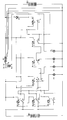
- the safety device for starting up immobilized vehicles which is the subject of the invention, is intended to serve as a linking element between a charged auxiliary battery (B1) which generally forms part of the actual device and a discharged battery (B2) linked to the immobilized vehicle. It consists of the functional association of four circuit sections, each one of them having switching and signalling elements, the first of which is formed by three relays (RL1), (RL2) and (RL3), in which the reference numbers (1) to (14) correspond in each case to the various terminals which each one of the relays has in order to establish the connections in the circuit.
- the device is connected to the discharged battery (B2) by means of clips available for this purpose.
- connections (2) and (6) belong to the coils of each one of the relays.
- (7) serves for switching (1) and (14)
- (1) of (RL1) serves for protecting the relay (RL4)
- (1) of (RL2) serves for protecting the relays (RL5) and (RL6).
- the connections (14) of these three relays are intended to illuminate the red light (P1).
- This circuit is not started up until incorrect use of the apparatus occurs, for example placing a 12-volt battery in a condition of polarity inversion with one of 24 volts, whereupon there would be 36 volts at the contacts (C1) and (C2) of the power relay (RL7).
- each one of these relays has an impedance of 450 ohms and, mounted in series, give a range of 1350 ohms which is suitable for the functioning of the circuit.
- the second circuit section includes a 24-volt relay (RL4) which is intended to protect the relays (RL5) and (RL6) against a change in polarity since, in this case, there would be 24 volts at the contacts of the relay (RL7) at the same time as the red light (P2) is illuminated, advising the operator of a malfunction.
- RL4 24-volt relay
- the third of the sections in question is composed of a 12-volt relay (RL5) which is actuated only when the terminals of the battery (B2) linked to the immobilized vehicle are in short-circuit, since 12 volts would appear at the contacts (C1) and (C2) of the relay (RL7). It is intended to disconnect (RL6), in order to prevent the 12 volts passing to it, and to illuminate the red light (P3).
- RL5 12-volt relay
- the fourth section of the circuit is formed by the relay (RL6) and a timer (T) and it is responsible for actuating the whole assembly. If the act of connecting up the batteries has been carried out correctly, i.e. connecting the terminals of the battery (B2) to the corresponding terminals of the battery (B1), the device remains on standby, awaiting the operator's turn of the vehicle's ignition key.
Landscapes
- Engineering & Computer Science (AREA)
- Power Engineering (AREA)
- Secondary Cells (AREA)
- Safety Devices In Control Systems (AREA)
- Protection Of Static Devices (AREA)
Applications Claiming Priority (2)
| Application Number | Priority Date | Filing Date | Title |
|---|---|---|---|
| ES9501460 | 1995-07-20 | ||
| ES09501460A ES2112762B1 (es) | 1995-07-20 | 1995-07-20 | Dispositivo de seguridad para arranque de maquinas inmovilizadas. |
Publications (2)
| Publication Number | Publication Date |
|---|---|
| EP0756367A2 true EP0756367A2 (fr) | 1997-01-29 |
| EP0756367A3 EP0756367A3 (fr) | 1997-06-04 |
Family
ID=8291108
Family Applications (1)
| Application Number | Title | Priority Date | Filing Date |
|---|---|---|---|
| EP96500102A Withdrawn EP0756367A3 (fr) | 1995-07-20 | 1996-07-19 | Dispositif de sécurité pour démarrer des véhicules immobilisés |
Country Status (2)
| Country | Link |
|---|---|
| EP (1) | EP0756367A3 (fr) |
| ES (1) | ES2112762B1 (fr) |
Cited By (2)
| Publication number | Priority date | Publication date | Assignee | Title |
|---|---|---|---|---|
| EP2498369A4 (fr) * | 2011-06-08 | 2013-02-20 | Huawei Tech Co Ltd | Circuit de commande permettant d'empêcher un groupe de batteries d'être connecté de façon inversée et système d'alimentation électrique pour station de base |
| US20170194120A1 (en) * | 2015-12-31 | 2017-07-06 | Shenzhen Carku Technology Co., Ltd. | Electrical connection device |
Family Cites Families (9)
| Publication number | Priority date | Publication date | Assignee | Title |
|---|---|---|---|---|
| ES454188A1 (es) * | 1976-12-13 | 1977-12-01 | Gomez Gallardo Diego | Perfeccionamientos introducidos en los dispositivos de segu-ridad para detectar correcta polaridad o existencias de ave-vias en el arranque auxiliar de maquinas electricas. |
| US4527111A (en) * | 1984-04-12 | 1985-07-02 | Joseph N. Connell | Safety jumper cables |
| JPS6331430A (ja) * | 1986-01-15 | 1988-02-10 | タイ−ハ− ヤン | スイツチ回路 |
| US4769586A (en) * | 1986-03-07 | 1988-09-06 | Kazmierowicz Thaddeus V | Battery jumper cable apparatus |
| US4757250A (en) * | 1987-02-20 | 1988-07-12 | Scep, Inc. | Three-conductor booster cable assembly |
| US4871957A (en) * | 1988-04-04 | 1989-10-03 | James Taranto | Method and apparatus for the automatic connection of battery cables |
| US5103155A (en) * | 1990-11-30 | 1992-04-07 | Joannou Constantinos J | Battery charging cable system |
| US5189359A (en) * | 1991-01-22 | 1993-02-23 | Kronberg James W | Solid state safety jumper cables |
| DE9319881U1 (de) * | 1993-12-23 | 1994-08-04 | Hugo Junkers Werke GmbH, 82216 Maisach | Mobile Energieversorgungseinheit |
-
1995
- 1995-07-20 ES ES09501460A patent/ES2112762B1/es not_active Expired - Fee Related
-
1996
- 1996-07-19 EP EP96500102A patent/EP0756367A3/fr not_active Withdrawn
Cited By (3)
| Publication number | Priority date | Publication date | Assignee | Title |
|---|---|---|---|---|
| EP2498369A4 (fr) * | 2011-06-08 | 2013-02-20 | Huawei Tech Co Ltd | Circuit de commande permettant d'empêcher un groupe de batteries d'être connecté de façon inversée et système d'alimentation électrique pour station de base |
| US20170194120A1 (en) * | 2015-12-31 | 2017-07-06 | Shenzhen Carku Technology Co., Ltd. | Electrical connection device |
| US10404087B2 (en) * | 2015-12-31 | 2019-09-03 | Shenzhen Carku Technology Co., Ltd. | Electrical connection device comprising voltage detecting unit and polarity detecting unit |
Also Published As
| Publication number | Publication date |
|---|---|
| ES2112762B1 (es) | 1998-12-16 |
| ES2112762A1 (es) | 1998-04-01 |
| EP0756367A3 (fr) | 1997-06-04 |
Similar Documents
| Publication | Publication Date | Title |
|---|---|---|
| US6211577B1 (en) | Jump start circuit for a vehicle battery | |
| US4082992A (en) | Twin ignition and twin electrical start system for a vehicle | |
| US4769586A (en) | Battery jumper cable apparatus | |
| US3949289A (en) | Dual battery ignition and start system for a vehicle | |
| US4217534A (en) | Vehicle battery polarity indicator | |
| US4166241A (en) | Battery jumpering apparatus | |
| US4149093A (en) | Battery protection device | |
| US5170151A (en) | Method and assembly for disconnecting a battery from its operating system | |
| US3395288A (en) | Battery guard system | |
| US3343057A (en) | Booster supply service vehicles with polarity protection | |
| EP1265076B1 (fr) | Dispositif de sécurité pour tester l'isolation d'une heare omnibus à courent continue | |
| JP3769843B2 (ja) | 電気自動車の強電リレー診断装置 | |
| US4488147A (en) | Battery jumper cable system | |
| US5796255A (en) | Electronic controlled, spark free booster cable system | |
| JP2003512711A (ja) | 燃料電池の電気出力と絶縁電気回路網との切換え接続を制御するための方法および装置 | |
| US4527111A (en) | Safety jumper cables | |
| EP0648380B1 (fr) | Batteries de securite pour vehicules automobiles | |
| US4286172A (en) | Safety jumper cables | |
| US3341762A (en) | Boost supply with polarity protection | |
| US7795756B2 (en) | Portable generator interconnection device for traffic signal | |
| JP2016103445A (ja) | 安全装置 | |
| EP0756367A2 (fr) | Dispositif de sécurité pour démarrer des véhicules immobilisés | |
| USH1172H (en) | Vehicle battery jumper system | |
| DE102015007532B3 (de) | Verpolschutz für eine Starterbatterie eines Kraftfahrzeugs | |
| FR2498385A1 (fr) | Dispositif de distribution de courant electrique a securite sur engin volant leger equipe pour le vol aux instruments |
Legal Events
| Date | Code | Title | Description |
|---|---|---|---|
| PUAI | Public reference made under article 153(3) epc to a published international application that has entered the european phase |
Free format text: ORIGINAL CODE: 0009012 |
|
| AK | Designated contracting states |
Kind code of ref document: A2 Designated state(s): DE FR GB PT |
|
| PUAL | Search report despatched |
Free format text: ORIGINAL CODE: 0009013 |
|
| AK | Designated contracting states |
Kind code of ref document: A3 Designated state(s): DE FR GB PT |
|
| 17P | Request for examination filed |
Effective date: 19980213 |
|
| STAA | Information on the status of an ep patent application or granted ep patent |
Free format text: STATUS: THE APPLICATION IS DEEMED TO BE WITHDRAWN |
|
| 18D | Application deemed to be withdrawn |
Effective date: 19990202 |