EP0756476B1 - Stabilisierte knieprothese - Google Patents
Stabilisierte knieprothese Download PDFInfo
- Publication number
- EP0756476B1 EP0756476B1 EP96906341A EP96906341A EP0756476B1 EP 0756476 B1 EP0756476 B1 EP 0756476B1 EP 96906341 A EP96906341 A EP 96906341A EP 96906341 A EP96906341 A EP 96906341A EP 0756476 B1 EP0756476 B1 EP 0756476B1
- Authority
- EP
- European Patent Office
- Prior art keywords
- bearing
- flexion
- bearing element
- condyloid
- approximately
- Prior art date
- Legal status (The legal status is an assumption and is not a legal conclusion. Google has not performed a legal analysis and makes no representation as to the accuracy of the status listed.)
- Expired - Lifetime
Links
Images






Classifications
-
- A—HUMAN NECESSITIES
- A61—MEDICAL OR VETERINARY SCIENCE; HYGIENE
- A61F—FILTERS IMPLANTABLE INTO BLOOD VESSELS; PROSTHESES; DEVICES PROVIDING PATENCY TO, OR PREVENTING COLLAPSING OF, TUBULAR STRUCTURES OF THE BODY, e.g. STENTS; ORTHOPAEDIC, NURSING OR CONTRACEPTIVE DEVICES; FOMENTATION; TREATMENT OR PROTECTION OF EYES OR EARS; BANDAGES, DRESSINGS OR ABSORBENT PADS; FIRST-AID KITS
- A61F2/00—Filters implantable into blood vessels; Prostheses, i.e. artificial substitutes or replacements for parts of the body; Appliances for connecting them with the body; Devices providing patency to, or preventing collapsing of, tubular structures of the body, e.g. stents
- A61F2/02—Prostheses implantable into the body
- A61F2/30—Joints
- A61F2/38—Joints for elbows or knees
- A61F2/3868—Joints for elbows or knees with sliding tibial bearing
-
- A—HUMAN NECESSITIES
- A61—MEDICAL OR VETERINARY SCIENCE; HYGIENE
- A61F—FILTERS IMPLANTABLE INTO BLOOD VESSELS; PROSTHESES; DEVICES PROVIDING PATENCY TO, OR PREVENTING COLLAPSING OF, TUBULAR STRUCTURES OF THE BODY, e.g. STENTS; ORTHOPAEDIC, NURSING OR CONTRACEPTIVE DEVICES; FOMENTATION; TREATMENT OR PROTECTION OF EYES OR EARS; BANDAGES, DRESSINGS OR ABSORBENT PADS; FIRST-AID KITS
- A61F2/00—Filters implantable into blood vessels; Prostheses, i.e. artificial substitutes or replacements for parts of the body; Appliances for connecting them with the body; Devices providing patency to, or preventing collapsing of, tubular structures of the body, e.g. stents
- A61F2/02—Prostheses implantable into the body
- A61F2/30—Joints
- A61F2/38—Joints for elbows or knees
- A61F2/3886—Joints for elbows or knees for stabilising knees against anterior or lateral dislocations
-
- A—HUMAN NECESSITIES
- A61—MEDICAL OR VETERINARY SCIENCE; HYGIENE
- A61F—FILTERS IMPLANTABLE INTO BLOOD VESSELS; PROSTHESES; DEVICES PROVIDING PATENCY TO, OR PREVENTING COLLAPSING OF, TUBULAR STRUCTURES OF THE BODY, e.g. STENTS; ORTHOPAEDIC, NURSING OR CONTRACEPTIVE DEVICES; FOMENTATION; TREATMENT OR PROTECTION OF EYES OR EARS; BANDAGES, DRESSINGS OR ABSORBENT PADS; FIRST-AID KITS
- A61F2/00—Filters implantable into blood vessels; Prostheses, i.e. artificial substitutes or replacements for parts of the body; Appliances for connecting them with the body; Devices providing patency to, or preventing collapsing of, tubular structures of the body, e.g. stents
- A61F2/02—Prostheses implantable into the body
- A61F2/30—Joints
- A61F2002/30001—Additional features of subject-matter classified in A61F2/28, A61F2/30 and subgroups thereof
- A61F2002/30108—Shapes
- A61F2002/3011—Cross-sections or two-dimensional shapes
- A61F2002/30138—Convex polygonal shapes
- A61F2002/30156—Convex polygonal shapes triangular
-
- A—HUMAN NECESSITIES
- A61—MEDICAL OR VETERINARY SCIENCE; HYGIENE
- A61F—FILTERS IMPLANTABLE INTO BLOOD VESSELS; PROSTHESES; DEVICES PROVIDING PATENCY TO, OR PREVENTING COLLAPSING OF, TUBULAR STRUCTURES OF THE BODY, e.g. STENTS; ORTHOPAEDIC, NURSING OR CONTRACEPTIVE DEVICES; FOMENTATION; TREATMENT OR PROTECTION OF EYES OR EARS; BANDAGES, DRESSINGS OR ABSORBENT PADS; FIRST-AID KITS
- A61F2/00—Filters implantable into blood vessels; Prostheses, i.e. artificial substitutes or replacements for parts of the body; Appliances for connecting them with the body; Devices providing patency to, or preventing collapsing of, tubular structures of the body, e.g. stents
- A61F2/02—Prostheses implantable into the body
- A61F2/30—Joints
- A61F2002/30001—Additional features of subject-matter classified in A61F2/28, A61F2/30 and subgroups thereof
- A61F2002/30316—The prosthesis having different structural features at different locations within the same prosthesis; Connections between prosthetic parts; Special structural features of bone or joint prostheses not otherwise provided for
- A61F2002/30329—Connections or couplings between prosthetic parts, e.g. between modular parts; Connecting elements
- A61F2002/30383—Connections or couplings between prosthetic parts, e.g. between modular parts; Connecting elements made by laterally inserting a protrusion, e.g. a rib into a complementarily-shaped groove
- A61F2002/3039—Connections or couplings between prosthetic parts, e.g. between modular parts; Connecting elements made by laterally inserting a protrusion, e.g. a rib into a complementarily-shaped groove with possibility of relative movement of the rib within the groove
- A61F2002/30398—Sliding
- A61F2002/304—Sliding with additional means for limiting said sliding
-
- A—HUMAN NECESSITIES
- A61—MEDICAL OR VETERINARY SCIENCE; HYGIENE
- A61F—FILTERS IMPLANTABLE INTO BLOOD VESSELS; PROSTHESES; DEVICES PROVIDING PATENCY TO, OR PREVENTING COLLAPSING OF, TUBULAR STRUCTURES OF THE BODY, e.g. STENTS; ORTHOPAEDIC, NURSING OR CONTRACEPTIVE DEVICES; FOMENTATION; TREATMENT OR PROTECTION OF EYES OR EARS; BANDAGES, DRESSINGS OR ABSORBENT PADS; FIRST-AID KITS
- A61F2/00—Filters implantable into blood vessels; Prostheses, i.e. artificial substitutes or replacements for parts of the body; Appliances for connecting them with the body; Devices providing patency to, or preventing collapsing of, tubular structures of the body, e.g. stents
- A61F2/02—Prostheses implantable into the body
- A61F2/30—Joints
- A61F2002/30001—Additional features of subject-matter classified in A61F2/28, A61F2/30 and subgroups thereof
- A61F2002/30316—The prosthesis having different structural features at different locations within the same prosthesis; Connections between prosthetic parts; Special structural features of bone or joint prostheses not otherwise provided for
- A61F2002/30329—Connections or couplings between prosthetic parts, e.g. between modular parts; Connecting elements
- A61F2002/30433—Connections or couplings between prosthetic parts, e.g. between modular parts; Connecting elements using additional screws, bolts, dowels, rivets or washers e.g. connecting screws
-
- A—HUMAN NECESSITIES
- A61—MEDICAL OR VETERINARY SCIENCE; HYGIENE
- A61F—FILTERS IMPLANTABLE INTO BLOOD VESSELS; PROSTHESES; DEVICES PROVIDING PATENCY TO, OR PREVENTING COLLAPSING OF, TUBULAR STRUCTURES OF THE BODY, e.g. STENTS; ORTHOPAEDIC, NURSING OR CONTRACEPTIVE DEVICES; FOMENTATION; TREATMENT OR PROTECTION OF EYES OR EARS; BANDAGES, DRESSINGS OR ABSORBENT PADS; FIRST-AID KITS
- A61F2/00—Filters implantable into blood vessels; Prostheses, i.e. artificial substitutes or replacements for parts of the body; Appliances for connecting them with the body; Devices providing patency to, or preventing collapsing of, tubular structures of the body, e.g. stents
- A61F2/02—Prostheses implantable into the body
- A61F2/30—Joints
- A61F2/30767—Special external or bone-contacting surface, e.g. coating for improving bone ingrowth
- A61F2/30771—Special external or bone-contacting surface, e.g. coating for improving bone ingrowth applied in original prostheses, e.g. holes or grooves
- A61F2002/30878—Special external or bone-contacting surface, e.g. coating for improving bone ingrowth applied in original prostheses, e.g. holes or grooves with non-sharp protrusions, for instance contacting the bone for anchoring, e.g. keels, pegs, pins, posts, shanks, stems, struts
-
- A—HUMAN NECESSITIES
- A61—MEDICAL OR VETERINARY SCIENCE; HYGIENE
- A61F—FILTERS IMPLANTABLE INTO BLOOD VESSELS; PROSTHESES; DEVICES PROVIDING PATENCY TO, OR PREVENTING COLLAPSING OF, TUBULAR STRUCTURES OF THE BODY, e.g. STENTS; ORTHOPAEDIC, NURSING OR CONTRACEPTIVE DEVICES; FOMENTATION; TREATMENT OR PROTECTION OF EYES OR EARS; BANDAGES, DRESSINGS OR ABSORBENT PADS; FIRST-AID KITS
- A61F2220/00—Fixations or connections for prostheses classified in groups A61F2/00 - A61F2/26 or A61F2/82 or A61F9/00 or A61F11/00 or subgroups thereof
- A61F2220/0025—Connections or couplings between prosthetic parts, e.g. between modular parts; Connecting elements
-
- A—HUMAN NECESSITIES
- A61—MEDICAL OR VETERINARY SCIENCE; HYGIENE
- A61F—FILTERS IMPLANTABLE INTO BLOOD VESSELS; PROSTHESES; DEVICES PROVIDING PATENCY TO, OR PREVENTING COLLAPSING OF, TUBULAR STRUCTURES OF THE BODY, e.g. STENTS; ORTHOPAEDIC, NURSING OR CONTRACEPTIVE DEVICES; FOMENTATION; TREATMENT OR PROTECTION OF EYES OR EARS; BANDAGES, DRESSINGS OR ABSORBENT PADS; FIRST-AID KITS
- A61F2220/00—Fixations or connections for prostheses classified in groups A61F2/00 - A61F2/26 or A61F2/82 or A61F9/00 or A61F11/00 or subgroups thereof
- A61F2220/0025—Connections or couplings between prosthetic parts, e.g. between modular parts; Connecting elements
- A61F2220/0041—Connections or couplings between prosthetic parts, e.g. between modular parts; Connecting elements using additional screws, bolts, dowels or rivets, e.g. connecting screws
-
- A—HUMAN NECESSITIES
- A61—MEDICAL OR VETERINARY SCIENCE; HYGIENE
- A61F—FILTERS IMPLANTABLE INTO BLOOD VESSELS; PROSTHESES; DEVICES PROVIDING PATENCY TO, OR PREVENTING COLLAPSING OF, TUBULAR STRUCTURES OF THE BODY, e.g. STENTS; ORTHOPAEDIC, NURSING OR CONTRACEPTIVE DEVICES; FOMENTATION; TREATMENT OR PROTECTION OF EYES OR EARS; BANDAGES, DRESSINGS OR ABSORBENT PADS; FIRST-AID KITS
- A61F2230/00—Geometry of prostheses classified in groups A61F2/00 - A61F2/26 or A61F2/82 or A61F9/00 or A61F11/00 or subgroups thereof
- A61F2230/0002—Two-dimensional shapes, e.g. cross-sections
- A61F2230/0017—Angular shapes
- A61F2230/0023—Angular shapes triangular
-
- A—HUMAN NECESSITIES
- A61—MEDICAL OR VETERINARY SCIENCE; HYGIENE
- A61F—FILTERS IMPLANTABLE INTO BLOOD VESSELS; PROSTHESES; DEVICES PROVIDING PATENCY TO, OR PREVENTING COLLAPSING OF, TUBULAR STRUCTURES OF THE BODY, e.g. STENTS; ORTHOPAEDIC, NURSING OR CONTRACEPTIVE DEVICES; FOMENTATION; TREATMENT OR PROTECTION OF EYES OR EARS; BANDAGES, DRESSINGS OR ABSORBENT PADS; FIRST-AID KITS
- A61F2310/00—Prostheses classified in A61F2/28 or A61F2/30 - A61F2/44 being constructed from or coated with a particular material
- A61F2310/00005—The prosthesis being constructed from a particular material
- A61F2310/00011—Metals or alloys
- A61F2310/00029—Cobalt-based alloys, e.g. Co-Cr alloys or Vitallium
Definitions
- This invention relates to prosthetic joints generally, and more particularly to an improved, unconstrained prosthetic knee replacement for a dysfunctional knee.
- prior art knee endoprostheses there are basically two types of prosthetic replacement knees known generally as constrained and unconstrained knees.
- An example of an unconstrained or floating meniscal bearing knee is disclosed in Buechel et al Patent No. 4,340,978.
- An embodiment of the Buechel invention is manufactured and sold by Depuy, Inc. of Warsaw, Indiana.
- the bearing elements of these types of knees are manufactured with high density polyethylene such as that disclosed in Zachariades Patent No. 4,587,163 developed by Polteco Inc. of Alameda, California because of its superior wear resistant characteristics.
- prostheses which allow axial rotation and A-P motion in addition to flexion-extension motion have incongruent contact (usually theoretical point-contact) between the femoral and tibial bearing surfaces, have been known.
- Those prior art knee prostheses which do provide congruent or area bearing contact fail to provide the needed axial rotation, or when cruciates are present the needed anterior-posterior motion.
- This polycentric motion which results from the action of the cruciate ligaments and condylar shape, allows for more efficient utilization of muscle forces by providing a posterior shift of the axis when effective quadriceps action is important and an anterior shift when hamstrings effectiveness is important. Furthermore, in the human knee it is this action and the A-P shift, and the shape of the posterior condyles, which influence this motion so as to allow full flexion capability for the knee. Failure to provide appropriate knee geometry inhibits, when cruciate ligaments are present, this natural motion and thus tends to restrict muscle effectiveness and inhibit flexion. These restrictions tend to increase both loading on the prosthesis and loading between prosthesis and bone.
- cruciate ligaments are present, most surgeons would prefer their retention, since they provide important internal stabilizers and, together with the condylar geometry of the femur and tibia, control the rotation axis and A-P motion of the knee. Furthermore, these ligaments provide anterior-posterior stability. Thus, it is desirable to reserve the cruciate ligaments, even though reasonable stability can be provided by a properly designed full platform type prosthesis.
- An object of the present invention is to provide a knee prosthesis that is stabilized in its anterior and/or posterior movement throughout a substantial range of flexion.
- An implantable prosthetic device for forming a joint between a pair of human or animal bones comprising:
- a prosthetic knee is shown and described herein with respect to two configurations, which differ in the number of arcuate surfaces provided for sliding engagement between the femoral component and the bearing element as described in detail hereinafter.
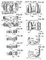
- the configuration shown and described in Figs. 1-21 describe the prosthetic knee design utilizing three arcuate surfaces on each of the condyles of the tibial component.
- the configuration shown in Figs. 22-32 utilizes only two arcuate surfaces for the improved knee as shown and described in detail herein. For convenience, the same numerals are used to describe the same element.
- the floating bearing prosthetic knee generally designated 10 in Fig. 1, provides area contact as opposed to line contact or point contact throughout the entire flexion/extension range of the prosthesis. Through this design, some degree of rollback automatically occurs as the knee flexes and additional rollback is allowed to will occur through the movement of the sliding bearing. Area contact throughout the full range of motion is obtained through the use of multiple arcuate sections along the path of conduct of the condyles with the bearing insert.
- the different radii and arcuate portions of the condyles lie in different sagittal or medial-lateral planes.
- tibial-femoral area contact will occur in different longitudinal planes throughout the flexion/extension range of the knee. Area contact will occur simultaneously in two planes only at the point of transition between the respective arcuate portions.
- the desirable prosthetic knee 10 satisfies at least five characteristics.
- the knee should have the normal polycentric motion of the normal knee joint.
- Two, unconstrained anterior-posterior motion and rotation would be permitted within the normal range of motion of the knee.
- Three, constrained A-P motion and rotation would occur at the limits of normal motion.
- Four, normal rollback of the femur with respect to the tibia should occur during flexion of the knee.
- Five, tibial-femoral contact pressure should be minimized in order to reduce wear on the polyethylene bearing insert 16.
- the prosthetic knee 10 satisfies these five characteristics as described hereinafter.
- the unconstrained knee is shown in perspective view to include a femoral component 12, a tibial component 14, and a bearing element 16.
- the femoral component 12 includes at least one upwardly extending stem 18 or other means for connection to the femur and a pair of condyles 20 on its inferior surface for engagement with the bearing portion 16.
- the bearing element 16 is constructed of a tough, wear-resistant, resilient material such as high density polyethylene.
- the remaining elements of the prosthetic knee are metallic and preferably manufactured of a cobalt-chromium alloy material approved for use in prosthetic devices.
- the tibial component includes a generally flat rigid platform 22 and a depending stem portion 24 for securing the tibial portion to the tibia.
- the superior surface of the femoral component and the implantable stem portion 24 and inferior surface of the platform 22 of the tibial component include a surface adapted for porous ingrowth to secure the prosthetic device within the tibia and femur, respectively, of the host or allograph bone of the patient.
- the condyles 20 of the femoral component are highly polished to reduce friction.
- the tibial portion includes the platform 22 and the depending stem 24.
- the platform is provided with a pair of laterally spaced, generally triangular-shaped, upward protrusions 26 and a centrally located aperture 28 for limiting the A-P movement of the bearing 16 described below.
- the bearing 16 includes a centrally located generally rectangular opening 32 which is used to slidably connect the bearing to the top of the tibial component 22.
- the bearing 16 has a generally flat inferior surface 34 as shown in Fig. 8 which slidably engages the superior surface or platform 22.
- the aperture 32 includes, at its lower end, a ridge or lip 36, of similar configuration. Both the aperture 32 and the vertical wall of the bearing have smooth or rounded corners to reduce stress.
- the bearing 16 is captured by a retaining means, generally designated 40, which includes a shoulder bolt 42, a retainer 44 and a spacer 46.
- the spacer 46 and retainer 44 are preferably manufactured of high density polypropylene, similar to that used for the bearing insert 16 and the shoulder bolt 42 would be made of stainless steel, titanium or cobalt-chromium alloy approved for use in this application.
- the shoulder bolt 42 includes a lower threaded portion 48 which engages a plurality of threads 50 at the lowermost end of the aperture 28 within the stem 24 of the tibial component.
- the shoulder sets the depth to prevent from the head 52 of the shoulder bolt from impeding the movement of the bearing insert 16.
- the retainer 46 includes an enlarged diameter ring 54 at its lowermost end which engages the platform 22 of the tibial portion 14 around the aperture 28 and extends upwardly coaxially with the shoulder bolt 42.
- the retainer or retaining element 44 is generally square in shape and includes a lower square portion 56 which forms a clearance fit within the ridge 36 at the lower end of the aperture 32 in the bearing, as can be seen in Fig. 5.
- the upper end of the retainer includes an enlarged flange 58 which engages the top of the step or lip 36.
- the retainer 44 is dimensioned so that the distance between the underside of the head 52 of the shoulder bolt and the top of the lip 36 provides a low tolerance clearance fit with the flange 58 of the retainer to allow the bearing 16 to slidably move on the platform 22 without becoming disengaged from the platform 22. In this manner, the bearing is free to slide in an anterior posterior or A-P path.
- the retainer 44 will stop the movement in the A-P direction as the front and rear surfaces engage the front or inner surfaces of the lip 36.
- the retaining means 40 in addition to permitting A-P movement of the bearing 16 also permits pivotal movement generally about the center line of the shoulder bolt 42.
- the bearing insert and the retainer may pivot about the center line of the shoulder bolt 42 to provide freedom of movement.
- the triangular protrusions 26 provide a stop means.
- the stop means includes the upward protrusions 26 and a pair of symmetrical cutouts 60 on the lower surface of the bearing insert 16.
- each cutout includes a generally flat rear wall 62 and a generally curved inner wall 64 for engagement with the upward protrusions 26.
- the height of the rear wall 62 permits the cutouts 60 to clear the top of the stops 26.
- the arcuate walls 64 of the bearing 16 engage the inner, generally right angle corner of the triangular protrusions 26 to virtually preclude most of the pivotal movement or rotational movement of the bearing insert 16.
- the bearing 16 is moved towards its posterior-most position, as shown in Fig. 15, the bearing is free to rotate in either direction as shown by arrows A and B and are limited by the longer upstanding walls of the protrusions 26 which engage the flat walls 62 within the cutout 60.
- the bearing insert 16 is constrained but is permitted to move in the A-P direction from the extremes as shown in Fig. 14 to that as shown in Fig. 16 while, at the same time, it is free to pivot about an axis defined by the shoulder bolt 24 within the limits created by the stop means where the walls 62 and 64 of the cutouts 60 engage the triangular protrusions 26.
- Some rollback automatically occurs (i.e., is obligated to occur) when tibiofemoral contact moves from one arcuate segment to the other one.
- the rest of the normal amount of rollback is allowed to occur (but not obligated to occur) with the movement of the bearing insert.
- the amount of additional rollback that is allowed to occur is governed by the interaction of the posterior cruciate ligament and the condylar surfaces.
- the rollback of the femur with respect to the tibia during flexion of the knee is an important characteristic of the present prosthesis because it causes the patellar tendon to move anteriorly with respect to the femur which greatly increases the effectiveness of the quadriceps muscle, especially when rising from a chair.
- the femoral component 12 includes generally a pair of condyles 20, securing posts 18 and a web portion which defines a patella track 70.
- the securing posts 18 provide means to secure the femoral component to the femur of a patient.
- a pair of matched apertures are drilled into the femur and the end of the femur is formed with five generally flat surfaces as shown to fit within the flat surfaces 72a through 72e as shown.
- the opposite surfaces 72a and 72e are generally parallel to one another and perpendicular to the surface 72c.
- the angled surfaces 72b and 72d are approximately at 45 degrees with respect thereto.
- the entire surface of the flat surfaces 72a-e and the surfaces of the posts 18 are designed for extramedullary bone growth to secure the femoral component to the end of the femur.
- the described femoral component and sliding bearing have congruent surfaces which allow for rotation and A-P motion within the range of normal A-P motion to prevent excessive anterior and posterior drawer and rotation and dislocation of the bearing.
- the upper surface of the bearing 16 is designed so that the inferior surfaces of the femoral component always have area contact at all flexion angles. Constant area contact is achieved by distributing the femoral contact areas on the bearing 16 across the frontal plane such that different areas of the bearing 16 are contacted through different angles of knee flexion. Each contact area on the bearing has the same radius of curvature as the portion of the inferior surface of the femoral component 12 in contact with the bearing.
- the bearing insert 16 is generally oval in shape with a pair of flat ends 80R and 80L.
- the anterior or front side is a generally flat arcuate wall 82 which includes a pair of cutouts 60 at the lower right and left ends, respectively.
- the posterior side includes a relatively large, almost semicircular recess 84 which provides substantial clearance for the posterior cruciate ligaments.
- the top portion of the rear wall on either side of the recess 84 includes a short generally vertical arcuate wall portion 86 which merges into a generally arcuate, inwardly tapered lower wall portion 88.
- the tapered portions 88 merge with a pair of lower chamfers at the bottom of the end walls 80R and 80L which terminate at their front ends with the cutouts 60.
- the superior surface of the bearing insert is described by a plurality of arcuate channels or grooves which are described in detail hereinafter in connection with the arcuate surfaces defined on the inferior contact surface of the femoral component.
- an upstanding flange 96 is included immediately anteriorly of the aperture 32.
- the outer edges of the top of the front wall 82 are softened by curves 98 as the transition to the top of the bearing insert 16.
- the contact surfaces between the bearing insert 16 and the femoral component 12 are best understood if considered together.
- the upper surface of the bearing 16 includes a plurality of arcuate surfaces for engagement with congruent arcuate surfaces on the inferior side of the femoral component 12.
- four of the arcuate surfaces have been labelled L and two of the surfaces have been labelled S.
- the four arcuate surfaces L are all generated using the same radius of curvature and similarly the two arcuate surfaces labelled S are generated using the same radius, which is smaller than the radius used to generate the surfaces L.
- the arcuate surface S shown in section view in Fig. 12 is defined posteriorly of the arcuate surfaces L, one of which is shown in sectional view in Fig. 11.
- the complementary surface of the femoral component includes four arcuate surfaces L and two arcuate surfaces S.
- the arcuate surfaces L and R lie in different sagittal planes as shown and make contact during different degrees of flexion of the knee.
- the arcuate surfaces L on the inferior surface of the femoral component are in contact with the arcuate surfaces L on the bearing 16 between approximately 0° through 8° of flexion of the knee and the arcuate surfaces S of the femoral component are in contact with the arcuate surfaces S of the bearing 16 during approximately 8° through 140° of flexion of the knee.
- area contact occurs between all of the arcuate surfaces L and S on the femoral component 12 with all of the arcuate surfaces L and S on the bearing component 16.
- the arcuate surfaces L are generated by radius R1 about a center point c. Center point C is slightly rearwardly defined relative to the post 18 and the radius R1 is approximately 4cm (1.60").
- the arcuate surfaces S are generated by a radius R2 about a center of rotation D.
- the radius R2 is approximately 1.9cm (0.75").
- the center of rotation D of radius R2 lies on a line passing through the center of rotation C of R1 so that the surfaces L and R have a tangent point T in order to have a smooth transition of tibia-femoral contact at approximately 8° of flexion.
- area contact of the arcuate surfaces L occurs during the first 8° of flexion of the knee and area contact is transferred to the arcuate sections S at approximately 8° and continues through maximum flexion of about 140°.
- the position of the femoral component 12 with regard to the bearing 16 is controlled by the center of rotation of curvature for the arcuate surfaces S or L which are in contact.
- the arcuate curves S are placed farther back on the bearing and will draw the femoral component posteriorly thus allowing obligatory rollback. Further rollback is permitted because the elongated aperture 32 in the bearing allows the bearing to move posteriorly on the tibial platform.
- the constraints 26 and the retaining means 40 prevent anterior movement of the bearing 16 beyond the anterior edge of the tibial component. Therefore, when rollback is occurring during flexion of the knee, no compensatory roll forward will occur between the bearing 16 and the tibial component 14.
- the arcuate surfaces L and S are designed to obtain the maximum amount of area contact possible within the permissible space.
- the arcuate surfaces S on the bearing 16 are approximately 1cm (3/8") wide and approximately 2.8cm (1-1/8") long.
- the radius R2 the radius for generating the arcuate surface S is approximately 1.9cm (0.75") and lies in a sagittal plane.
- the transverse radius which defines the arcuate surface in the medial lateral plane as shown in Fig. 5 is approximately 1cm (.375").
- the arcuate surfaces L are approximately 3.2 cm (1.25") in length generated by the radius R1 in the sagittal plane and the radius in the transverse plane R4 (Fig.
- the center of rotation D is approximately 1cm (0.375") posteriorly of the center of rotation C and about 2.3cm (0.9") below the center of rotation C.
- the centerlines of the arcuate surfaces L are approximately 0.8cm (0.3") on either side of the centerline of the arcuate section S and the respective centerlines of the arcuate sections S are approximately 5cm (2.00") apart.
- Figs. 22-32 describe another knee prosthesis, which as described previously, is simpler in design and provides better performance. This differs in several respects but primarily in the number of arcuate surfaces in contact between the femoral component 12 and the bearing surface 16. In particular, it uses two arcuate surfaces on either side of the midline of the femoral component and the bearing surface as to the design which includes three arcuate surfaces described previously with respect to Figs. 1-21.
- the femoral component includes a pair of condyles 20 each of which includes two arcuate surfaces L and S.
- the arcuate surfaces L on the inferior surface of the femoral component are in contact with congruent arcuate surfaces L on the bearing element 16 between approximately 0 and 8° of flexion of the knee.
- the arcuate surfaces F of the femoral component are in contact with the arcuate surfaces S of the bearing element 16 during approximately 8° through 140° of flexion of the knee.
- area contact occurs between all of the arcuate surfaces L and S of the femoral component 12 with all of the arcuate surfaces L and S on the bearing component 16.
- FIG. 3 shows in detail the two radii R1 which generates the arcuate surface L and R2 which generates the arcuate surface S have a common center of rotation where the center of rotation of R2 lies on the radii R1 at point D so that a line tangent to R1 and R2 can be drawn only at the point where a line through points C and D intersect the arcuate surface.
- the position of the femoral component 12 of Fig. 29 with regard to the bearing element 16 of Fig. 22 is controlled by the center of rotation of curvature for the arcuate surfaces S or L which are in contact.
- the arcuate surfaces S are placed further back on the bearing and will draw the femoral component posteriorly, thus allowing obligatory rollback. Further rollback is permitted because the elongated aperture 32 in the bearing allows the bearing to move posteriorly on the tibial platform.
- the constraints 26 on the tibial platform and the retaining means 40 prevent anterior movement beyond the interior edge of the tibial platform.
- the arcuate surfaces s terminate in a high front wall 120 which provides for a substantially longer, forwardly extended arcuate surface S which provides substantially enhanced posterior stability. This feature will permit the retention of the cruciate ligament if desired.
- each condyle portion 20 permits the use of a larger radius in the M-L direction.
- the radius R3 which defines the arcuate surface S and the radius R4 which defines the arcuate surface L are larger, therefore providing substantially more contact area for a particular prosthesis.
- the size of the prosthetic knee of Figs. 22-30 will again vary for each patient.
- the general or approximate dimensions described with respect to Figs. 1-20 will be similar with respect to those of Figs. 22-32 except that the radii defining the arcuate surfaces in the transverse plane are substantially larger.
- the larger radius R3 is particularly advantageous when encountering liftoff as described previously.
- the larger surface area of the larger arcs provide substantial additional stability.
- the knee prosthesis 10 of both arrangements illustrated is the only design which gives area contact between the bearing 16 and the femoral component 12 in all degrees of flexion.
- the highest pressures on the knee joint are experienced during stair climbing where the knee is flexed to approximately 90 degrees of flexion in which the prior art knees have only line contact or point contact.
- polyethylene the material used to form the bearing
- area contact is more important in stair climbing or rising from a chair than when walking, even though the former may be performed much less often.
- the prosthetic knee 10 also permits the use of the same component in the presence or absence of posterior cruciate ligaments.
- semiconstrained knee prosthesis require the presence of posterior cruciate ligaments to prevent posterior subluxation of the tibia.
- constrained prosthesis which do not allow rollback, require removal of the posterior cruciate ligaments because proper tension on the posterior cruciate ligaments would attempt to create posterior rollback which is prevented by the constraints. This could lead to dislocation of the components of the constrained prosthesis or rupture of the posterior cruciate ligaments.
- Figs. 18-21 which show the movement of the elements of both arrangements of the prosthetic knee 10 implanted in a patient
- the bearing insert 16 moves to its anterior-most position with respect to the tibial component 14.
- the arcuate surfaces L on the respective tibial component and bearing insert 16 are in engagement.
- rollback of the femur with respect to the tibia begins to occur to approximately the maximum position as shown in Fig. 21 where the bearing insert 16 has moved to its posterior-most position emulating, as close as possible, the normal knee.
- this prosthetic knee more closely simulates the normal knee movement than earlier devices.
- the prosthesis 10 provides normal polycentric motion for the knee joint and permits normal rollback of the femur with respect to the tibia during flexion.
- the rotational and anterior-posterior movement of the bearing insert is unconstrained for the normal range of motion but is constrained at its limits.
- the design of the polycentric- contact surfaces between the femoral component 12 and the bearing insert 16 assure for sufficient area contact throughout the flexion/extension range of the knee to minimize pressure and resultant wear on the bearing insert.
- FIGS. 33 and 34 show rear elevational and side cross-sectional exploded views of a prosthetic knee, generally at 200.
- the prosthetic knee 200 includes a first fixation means adapted for fixation to one of the bones, which is shown in the form of a femoral component 202.
- the femoral component 202 is preferably shaped so as to be disposed upon a resected femur.
- the femoral component 202 is shown to include a first bearing surface 204 that preferably includes at least two, convex, laterally adjacent, arcuate bearing portions of differing radii. As described here, the first bearing surface 204 represents at least a substantial portion of the inferior surface of the femoral component 202 when considered in a medial-lateral direction.
- the arcuate bearing portions are shown in this arrangement to each include a pair of condylar portions 206 and 208.
- the condylar portions 206 and 208 each include two laterally spaced apart condyloid elements defined by laterally spaced, arcuate segments of different radii. As such, each condyloid element within a given condylar portion has a different axis of rotation.
- these condyloid elements are provided as a first inner condyloid element 210, a first outer condyloid element 212, a second inner condyloid element 214 and a second outer condyloid element 216.
- the inner condyloid elements 210 and 214 are each constructed to a substantially matching radius of curvature and the outer condyloid elements 212 and 216 are each constructed to a substantially matching radius of curvature as well.
- the radius for the inner condyloid elements is substantially larger than that corresponding to the outer condyloid elements.
- the inner condyloid elements 210 and 214 are of radius 4.2 cm (1.645) in., while the outer condyloid elements 212 and 216 are of radius 2cm (0.800 in). It will be appreciated, however, that any suitable radius selections may be made for these or any other chosen configuration for the condyloid elements making up the condylar portions 206 and 208. In order to enhance a smooth sliding transition of area contact between the inner condyloid elements and the outer condyloid elements, the radii of the inner condyloid elements and the outer condyloid elements preferably intersect. It will be appreciated that any of the arrangements previously described or other arrangements for the first bearing surface 204 may also be suitable.
- the prosthetic knee 200 is also shown to include a second fixation means adapted for attachment to the other bone, which is shown in the form of a tibial component 218.
- the tibial component 218 includes an integral device for enhancing a secured relation of the tibial component 218 to a resected tibia.
- This is provided in a preferred embodiment as a fixation shaft 220 that is operable for being inserted for fixation into a tibial intermedullary canal.
- One preferred shape for the fixation shaft 220 is an elongated conical shape that is insertable into a correspondingly shaped tibial intermedullary canal, although other suitable shapes may be used.
- the tibial component 218 preferably includes means for engaging a bearing element as will be discussed below.
- This may be provided as a recess 222 that is formed in a conical shape which allows for insertion and relative rotation of a portion of the bearing element discussed below. It will be appreciated, however, that this engagement may also be in a form that allows independent anterior-posterior movement, medial-lateral movement and rotational movement. Alternatively, any other suitable means for engaging a bearing element may be used.
- the tibial component 218 is also shown to include a second bearing surface 224 lying in a plane generally perpendicular to a longitudinal axis of the tibial component 218, which may be defined by the axis of the recess 222.
- the prosthetic knee 200 is also shown to include a bearing element 226 disposed between the femoral component 202 and the tibial component 218.
- the bearing element 226 includes means for engaging the tibial component 218.
- the engagement between the bearing element 226 and the tibial component 218 may in one form be a rotatable inserted engagement.
- this is provided as an engagement post 228 of complementary shape to the recess 222.
- the engagement post 228 may be truncated at its lower end.
- the bearing element 226 also includes a lower bearing surface 230 that is operable for engaging the second bearing surface 224 in a sliding rotatable manner.
- the means for engaging the tibial component 218 is provided as set forth above, other suitable means may be used.
- this engagement may also be in a form that allows limited or unlimited movement in some or all directions within a horizontal plane as a floating bearing situation.
- the present invention contemplates the possibility of three degrees of freedom between the bearing element 226 and the tibial component 218, namely, anterior-posterior motion, medial-lateral motion and rotation. Simultaneous motion in any or all of these directions is thus contemplated.
- the bearing element 226 also includes an upper bearing surface 232 that is a complementary concave surface for engaging the various components forming the first bearing surface 204 of the femoral component 202.
- the upper bearing surface 232 is shown to include a first inner concave surface 234, a first outer concave surface 236, a second inner concave surface 238 and a second outer concave surface 240. These surfaces are preferably shaped in a complementary relation to the first inner condyloid element 210, first outer condyloid element 212, second inner condyloid element 214 and second outer condyloid element 216, respectively.
- first inner concave surface 234 and the second inner concave surface 238 are formed to substantially the same radius of curvature, while the first outer concave surface 236 and the second outer concave surface 240 are formed to substantially the same radius of curvature.
- the radii corresponding to these portions will also preferably intersect, as before.
- the inner condyloid elements 210 and 214 of the femoral component 202 are preferably operable for being in area contact with the inner concave surfaces 234 and 238 of the bearing element 226 from approximately -6° of flexion, through 0° of flexion, or full extension, to approximately 71 ⁇ 2° to 8° of flexion.
- the outer condyloid elements 212 and 216 are operable for being in area contact with the outer concave surfaces 236 and 240 beyond approximately 71 ⁇ 2° of flexion. Sliding rotation of the condyloid elements against the concave surfaces results in a transfer of area contact from the inner surfaces to the outer surfaces at approximately 71 ⁇ 2° of flexion.
- the prosthetic knee 200 of the present invention may include additional condyloid elements and concave surfaces that are suitable for sliding rotation engagement. These surfaces may be in area contact over other ranges of flexion, including the situation where one or more pairs of complementary surfaces are in area contact over the entire range of flexion. As such, the present invention is intended to contemplate arrangements where various combinations of complementary regions of area contact are present over the entire range of flexion.
- the presence of area contact between surfaces of the femoral component 202 and the bearing element 226 enhances a stabilized condition of the prosthetic knee 200. This occurs by providing additional surface area in the medial-lateral plane over which load may be generally distributed. This is preferably accomplished through the use of arcuate bearing surfaces as viewed in the medial-lateral plane. Area contact between the femoral component 202 and the bearing element 226 also provides enhanced stability by allowing area contact to be maintained between the femoral component 202 and the bearing element 226 on one side of the anterior-posterior centerline in the event of slight liftoff on the opposite side of the centerline. This arrangement is especially preferred over designs having flat bearing surfaces in the medial-lateral plane in order to provide area contact upon liftoff rather than point contact. This arrangement is also preferred over designs having convex bearing surfaces in the medial-lateral plane, but do not accomplish area contact, in order to provide area contact upon liftoff rather than line contact
- the bearing element 226 further includes a first stabilization member for enhancing a stabilized condition of the prosthetic knee 200 by both controlling articulation and inhibiting disarticulation between the first bearing surface 204 and the bearing element 226.
- the stabilization member is also operable to provide a stop on the bearing element 226 against which a portion of the first bearing surface 204 may rest when the desired limit of articulation at or beyond full extension is reached.
- the first stabilization member is provided in a preferred embodiment as a posterior stabilization member 242 disposed adjacent to an anterior surface of the bearing element 226.
- the posterior stabilization member 242 is operable to limit posterior movement of the tibial component 218 throughout the entire range of flexion, including full extension.
- the posterior stabilization member 242 preferably takes the form of a rounded protuberance disposed in the central region of the bearing element 226, between the first and second inner concave surfaces 234 and 238 at an anterior location.
- the posterior stabilization member 242 includes lateral edges which may be generally parallel and substantially perpendicular to the lower bearing surface 230, for providing lateral limits on its travel. It will be appreciated, however, that other suitable shapes for the posterior stabilization member 242 may be used.
- a cam 244 is located on the first bearing surface 204.
- the cam 244 is disposed upon a substantial, but incomplete, portion of the first bearing surface 204 at its central region.
- the first bearing surface 204 is intended to include at least a portion of the cam 244.
- the cam 244 is shaped and positioned so that the posterior stabilization member 242 is in close proximity to the cam 244 from approximately -6° of flexion to approximately 71 ⁇ 2° to 8° of flexion, and is in area contact with the cam 244 from approximately 71 ⁇ 2° of flexion to full flexion.
- an advantage of the area contact between the posterior stabilization member 242 and the cam 244 is the distribution of load over an enlarged surface area.
- the cam 244 is preferably shaped to maintain the same close proximity or area contact with the posterior stabilization member 242 during both articulation regions. For this reason, the cam 244 is formed in part with a radius of curvature approximately equal to the radius of the first and second outer condyloid elements 212 and 216.
- the posterior stabilization member 242 is therefore able to travel either in area contact with or in close proximity to the cam 244 as the first and second outer condyloid elements 212 and 216 articulate against the first and second outer concave surfaces 236 and 240. This region of simultaneous travel preferably occurs during the same range of flexion as the articulation of the first and second outer condyloid elements 212 and 216, namely, beyond approximately 71 ⁇ 2° of flexion.
- the cam 244 is formed in part with region of curvature at its anterior end corresponding to the radius for the first and second inner condyloid elements 210 and 214.
- the posterior stabilization member 242 travels either in area contact with or in close proximity to the cam 244 as the first and second inner condyloid elements 210 and 214 articulate against the first and second inner concave surfaces 234 and 238.
- This region of simultaneous travel preferably occurs during the same range of flexion as the articulation of the first and second inner condyloid elements 210 and 214, namely, between approximately -6° of flexion and approximately 71 ⁇ 2° of flexion.
- the cam 244 is shaped to at least two radii of curvature, one corresponding to articulation of the inner surfaces, and the other to articulation of the outer surfaces.
- the cam 244 is preferably formed to have specifically shaped lateral walls that are complementary to the lateral edges of the posterior stabilization member 242.
- the insertion of the posterior stabilization member 242 within the cam 244 is operable to limit lateral movement between the femoral component 202 and the bearing element 226. This enhances a stabilized condition of the prosthetic knee 200 as a whole.
- the cam 244 is also preferably operable to inhibit disarticulation at the desired limit of full extension or hyperextension. This is accomplished by allowing the posterior stabilization member 242 to contact the anterior end of cam 244 in an abutting relation. This limiting contact is possible regardless of whether the first stabilization member 242 and the cam 244 are in close proximity or in area contact during predetermined ranges of flexion. When the posterior stabilization member 242 contacts the anterior end of the cam 244, this represents either a limit reached at the end of the desired articulation range, or the engagement of these components after slight disarticulation, in the situation where the posterior stabilization member 242 is maintained in close proximity during flexion.
- the posterior stabilization member 242 and the cam 244 may have a single longitudinal region of protrusion and corresponding recess or two or more longitudinally sequential regions of protrusions and corresponding recesses that enhance stability by distributing load additionally over a greater surface area in the medial-lateral plane.
- the posterior stabilization member 242 and the cam 244 may also have one or more laterally adjacent regions of condyloid elements and concave surfaces incorporated into their surfaces that also enhance stability by additionally distributing load.
- These surfaces are preferably shaped so that their engagement follows and complements the engagement of the condyloid elements 210, 212, 214 and 216 and the concave surfaces 234, 236, 238 and 240 over one or more of the same ranges of flexion.
- a single region of protrusion and corresponding recess may complement the engagement of the condyloid elements with the concave surfaces over a portion, up to the entire range, of flexion.
- Multiple regions of longitudinally sequential protrusions and recesses, or laterally adjacent condyloid elements and concave surfaces may complement the engagement of the condyloid elements with the concave surfaces partially or completely over two or more regions of flexion, and may complement each other to cause sequential engagements covering up to the entire range of flexion.
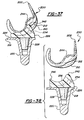
- FIGS. 35-37 there are shown three side cross-sectional views of the same device shown in FIGS. 33 and 34, but in assembled form, and at three stages of articulation. For ease in understanding, similar components have retained similar reference numerals throughout.
- FIG. 35 is a side cross-sectional view of the prosthetic knee 200 at approximately full extension, or 0° flexion.
- the first inner condyloid element 210 and the second inner condyloid element (not shown) are in area contact with the first inner concave surface 234 and the second inner concave surface (not shown).
- the posterior stabilization member 242 is in proximity to, but is not in contact with, the cam 244.
- FIG. 36 is a side cross-sectional view of the prosthetic knee 200 at approximately 71 ⁇ 2° flexion.
- the first inner condyloid element 210 and the second inner condyloid element are in area contact with the first inner concave surface 234 and the second inner concave surface (not shown).
- the first outer condyloid element 212 and the second outer condyloid element are simultaneously in area contact with the first outer concave surface 236 and the second outer concave surface (not shown). This simultaneous area contact occurs at the transition point between the respective arcuate portions.
- the posterior stabilization member 242 begins its contact with the cam 244.
- FIG. 37 is a side cross-sectional view of the prosthetic knee 200 at intermediate flexion.
- the first outer condyloid element 212 and the second outer condyloid element (not shown) are in area contact with the first outer concave surface 236 and the second outer concave surface (not shown).
- the posterior stabilization member 242 is in area contact with the cam 244.
- the bearing element 226 further includes an anterior stabilization member 246 disposed adjacent a posterior surface of the bearing element 226 which serves to limit anterior movement of the tibial component 218.
- the anterior stabilization member 246 is a rounded protuberance disposed in the central region of the first bearing surface 204, between the first and second inner concave surfaces 234 and 238 at a posterior location.
- the anterior stabilization member 246 is operable to be in close proximity to at least a portion of the first bearing surface 204 over one or more substantial ranges of flexion. In one preferred arrangement, the anterior stabilization member 246 is operable to be in close proximity to the cam 244 over a substantial range of flexion.
- the anterior stabilization member 246 may be similarly constructed to have one or more protrusions and/or recesses that communicate with corresponding recesses and/or protrusions upon the cam 244.
- the anterior stabilization member 246 preferably has specifically shaped lateral edges, which may be parallel and substantially perpendicular to the lower bearing surface 230, to limit lateral movement of the femoral component 202 with respect to the tibial component 218. In such a configuration, the anterior stabilization member 246 is also able to enhance lateral stabilization of the prosthetic knee 200 during flexion. It will be appreciated that other suitable shapes for the anterior stabilization member 246 may be employed.
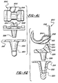
- FIGS. 39 and 40 Another preferred embodiment of the present invention is illustrated with reference to FIGS. 39 and 40.
- the components are substantially similar to that previously described, except for an additional set of cooperating articulation surfaces for further controlling articulation and enhancing stability and area contact of the prosthetic knee 200.
- This embodiment is one possible arrangement for additional articulation surfaces on the posterior stabilization member 242 and the cam 244 as previously mentioned.
- the bearing element 226 includes a first articulation surface 248, preferably located along the arcuate surface of at least a portion of and possibly all of, the posterior stabilization member 242.
- the first articulation surface 248 is preferably a rounded protuberance having the capability of area contact in several planes at once along its length.
- first articulation surface 248 to be disposed upon the anterior surface and upon a portion of the posterior surface of the posterior stabilization member 242.
- This configuration allows the first articulation surface to be operable for area contact from approximately -6° of flexion to approximately 71 ⁇ 2° of flexion.
- Other shapes for the first articulation surface 248 may also be employed. Such other shapes may cause the first articulation surface 248 to be operable for area contact over a wider range of flexion. It will be appreciated that any of the additional articulation surfaces set forth herein may be disposed upon the anterior stabilization member 246 alone, or in conjunction with additional lengths of the same or different articulation surfaces disposed upon the posterior stabilization member 242.
- the prosthetic knee 200 may also include a corresponding recess upon the femoral component 202 for engaging the first articulation surface 248.
- This is provided as a cam bearing surface 250 disposed along at least a portion of the length of the cam 244.
- the cam bearing surface 250 is shaped complementary to the first articulation surface 248 so that the first articulation surface 248 may travel by sliding through the cam bearing surface 250 during the articulation of the remaining components.
- the cooperation of the first articulation surface 248 with the cam bearing surface 250 occurs from approximately -6° of flexion to approximately 71 ⁇ 2° of flexion, as set forth in FIGS. 39 and 40, although it may alternatively occur for one or more different portions of the flexion range, including throughout the entire range of flexion. It will be appreciated that the presence of these additional components may result in the variance in dimensions of the femoral component 202 and the bearing element 226.
- a reverse arrangement may be provided, wherein a second articulation surface 252 is located upon the femoral component 202 for engaging a corresponding recess such as a stabilization member bearing surface 254 upon the bearing element 226.
- the shape for the second articulation surface 252 may be a rounded shape, although other shapes may be employed.
- the second articulation surface 252 is disposed upon the anterior region of the cam 244, with the corresponding stabilization member bearing surface 254 being disposed upon the anterior region and a portion of the posterior region of the posterior stabilization member 242.
- the preferred range of flexion over which these surfaces are in area contact is from approximately -6° of flexion to approximately 71 ⁇ 2° of flexion, as shown in FIGS. 41 and 42, although it may alternatively occur for only one or more portions of the flexion range, including throughout the entire range of flexion. As before, these surfaces may also be disposed in different locations of close proximity along the anterior stabilization member 246 alone, or in conjunction with additional lengths of the same or different cooperating surfaces disposed upon the posterior stabilization member 242.
- FIG. 43 sets forth such an embodiment, wherein an engagement post 228 of reduced cross-section, compared to the cross-section of the recess 222, is provided upon the bearing element 226.
- This configuration provides a limited freedom of movement to the bearing element 226 with respect to the tibial component 218. This movement may be in an anterior-posterior direction, in a medial-lateral direction, in rotation and in any combination of the above. A limited floating bearing situation is thus provided.
- a limited floating bearing situation may also be provided by altering the configuration of the aperture 32, the shoulder bolt 42, the retainer 44 and the spacer 46 in FIGS. 2, 5 and 6. For example, widening the aperture 32 and increasing the head diameter of the shoulder bolt 42 may allow limited movement beyond the anterior-posterior direction alone.
- FIG. 44 shows an extension of the freedom of movement principle.
- the bearing element 226 is shown to include a lower bearing surface 230 that is operable to be substantially flush with the second bearing surface 224. In this arrangement, the recess 222 and the engagement post 228 are not included. This provides a floating bearing situation.
Landscapes
- Health & Medical Sciences (AREA)
- Orthopedic Medicine & Surgery (AREA)
- Heart & Thoracic Surgery (AREA)
- Vascular Medicine (AREA)
- Oral & Maxillofacial Surgery (AREA)
- Transplantation (AREA)
- Engineering & Computer Science (AREA)
- Biomedical Technology (AREA)
- Physical Education & Sports Medicine (AREA)
- Cardiology (AREA)
- Life Sciences & Earth Sciences (AREA)
- Animal Behavior & Ethology (AREA)
- General Health & Medical Sciences (AREA)
- Public Health (AREA)
- Veterinary Medicine (AREA)
- Prostheses (AREA)
- Steroid Compounds (AREA)
- Materials For Medical Uses (AREA)
Claims (16)
- Implantierbare Prothesenvorrichtung (200) zur Bildung eines Gelenks zwischen einem Paar menschlicher oder tierischer Knochen, mit:dadurch gekennzeichnet, dasseinem zur Befestigung an einem der Knochen geeigneten ersten Befestigungsmittel (202);einer ersten Auflagefläche (204) auf dem genannten ersten Befestigungsmittel (202), wobei die genannte erste Auflagefläche (204) mindestens zwei konvexe, seitlich nebeneinander liegende, bogenförmige Tragteile (206, 208) mit unterschiedlichem Radius aufweist;einem zur Befestigung an dem anderen Knochen geeigneten zweiten Befestigungsmittel (218);einer zweiten Auflagefläche (224) auf dem genannten zweiten Befestigungsmittel (218), wobei die genannte zweite Auflagefläche (224) in einer zu einer Längsachse des genannten zweiten Befestigungsmittels (218) insgesamt senkrechten Ebene liegt; undeinem Tragelement (226) zwischen der genannten ersten Auflagefläche (204) und der genannten zweiten Auflagefläche (224), das zum Eingriff in die erste Auflagefläche (204) an einer Seite eine komplementäre konkave Fläche und zur Verbindung mit der genannten zweiten Auflagefläche (224) eine gegenüberliegende Fläche (230) aufweist, um mindestens eine Relativbewegung nach vorn und nach hinten oder eine Relativbewegung zur Mitte und zur Seite oder eine Drehbewegung zu erlauben,
das genannte Tragelement (226) ferner Mittel zum Verhindern einer Exartikulation zwischen dem genannten Tragelement (226) und der genannten ersten Auflagefläche (204) umfasst, wobei die genannten Mittel zum Verhindern einer Exartikulation ein hinteres Stabilisierungselement (242) in Form eines neben einer vorderen Fläche des genannten Tragelements (226) angeordneten abgerundeten konvexen Vorsprungs und einen Nocken (244) in Form einer konkaven Fläche in der genannten Auflagefläche umfassen und das hintere Stabilisierungselement (242) während der Beugung von ungefähr -6° bis ungefähr 7½°in nächster Nähe des genannten Nockens (244) angeordnet ist, wodurch die geringfügige Exartikulation zwischen der genannten ersten Auflagefläche (204) und dem genannten Tragelement (226) den Eingriff des genannten hinteren Stabilisierungselements (242) in den genannten Nocken (244) bewirkt, und während der Beugung von ungefähr 7½° bis zur vollständigen Beugung in Flächenkontakt mit dem genannten Nocken (244) kommt;
und ein vorderes Stabilisierungselement (246) in Form eines neben einer hinteren Fläche des genannten Tragelements (226) angeordneten abgerundeten Vorsprungs, wobei das genannte vordere Stabilisierungselement (246) zum Verhindern einer Exartikulation zwischen der genannten ersten Auflagefläche (204) und dem genannten Tragelement (226) zum Einsatz gebracht werden kann. - Prothesenvorrichtung nach Anspruch 1, dadurch gekennzeichnet, dass das genannte Tragelement (226) eine Eingriffsvorrichtung (228) aufweist und dass das genannte zweite Befestigungsmittel (218) Mittel (222) zum Eingriff in die genannte Eingriffsvorrichtung (228) aufweist.
- Prothesenvorrichtung nach Anspruch 1, dadurch gekennzeichnet, dass das genannte zweite Befestigungsmittel (218) eine Ausnehmung (222) aufweist und dass das genannte Tragelement (226) einen für den durch Einschieben bewirkten drehbaren Eingriff in die Ausnehmung (222) einsetzbaren Zapfen (228) aufweist.
- Prothesenvorrichtung nach Anspruch 1, dadurch gekennzeichnet, dass das genannte zweite Befestigungsmittel (218) eine Ausnehmung (222) aufweist und dass das genannte Tragelement (226) einen für den durch Einschieben bewirkten gleitenden Eingriff in die Ausnehmung (222) einsetzbaren Zapfen (228) aufweist.
- Prothesenvorrichtung nach Anspruch 1, dadurch gekennzeichnet, dass die erste Auflagefläche (204) ein Paar Kondylenteile (206, 208) aufweist, wobei jeder Kondylenteil (206, 208) zwei seitlich voneinander beabstandete kondylenförmige Elemente (210, 212, 214, 216) aufweist, die durch seitlich voneinander beabstandete bogenförmige Segmente von unterschiedlichem Radius gebildet werden.
- Prothesenvorrichtung nach Anspruch 5, dadurch gekennzeichnet, dass jedes kondylenförmige Element (210, 212, 214, 216) innerhalb eines Kondylenteils (206, 208) eine unterschiedliche Drehachse aufweist.
- Prothesenvorrichtung nach Anspruch 5, dadurch gekennzeichnet, dass jeder Kondylenteil (206, 208) ein innen liegendes kondylenförmiges Element (210, 214) und ein außen liegendes kondylenförmiges Element (212, 216) aufweist, wobei jedes innen liegende kondylenförmige Element (210, 214) über einen substantiellen Bereich der Beugung für den Flächenkontakt mit einer konkaven Fläche des genannten Tragelements (226) und jedes außen liegende kondylenförmige Element (212, 216) über einen substantiellen Bereich der Beugung für den Flächenkontakt mit einer konkaven Fläche des genannten Tragelements (226) einsetzbar ist.
- Prothesenvorrichtung nach Anspruch 5, dadurch gekennzeichnet, dass jeder Kondylenteil (206, 208) ein innen liegendes kondylenförmiges Element (210, 214) und ein außen liegendes kondylenförmiges Element (212, 216) aufweist, wobei jedes innen liegende kondylenförmige Element (210, 214) von ungefähr -6° Beugung bis ungefähr 7½° Beugung für den Flächenkontakt mit einer konkaven Fläche des genannten Tragelements (226) einsetzbar ist, und jedes außen liegende kondylenförmige Element (212, 216) bei über ungefähr 7½° Beugung für den Flächenkontakt mit einer konkaven Fläche des genannten Tragelements (226) einsetzbar ist.
- Prothesenvorrichtung nach Anspruch 7, dadurch gekennzeichnet, dass der Flächenkontakt zwischen dem genannten Tragelement (226) und jedem innen liegenden kondylenförmigen Element (210, 214) einen ersten Gleitkontaktbereich darstellt und der Flächenkontakt zwischen dem genannten Tragelement (226) und jedem außen liegenden kondylenförmigen Element (212, 216) einen zweiten Gleitkontaktbereich darstellt und dass der genannte erste Gleitkontaktbereich bei ungefähr 7½° Beugung den genannten zweiten Gleitkontaktbereich schneidet.
- Prothesenvorrichtung nach Anspruch 1, dadurch gekennzeichnet, dass das genannte Mittel zum Verhindern der Exartikulation eine in Längsrichtung hervorstehende Fläche (248) aufweist, die zum Eingriff in eine entsprechende auf der genannten ersten Auflagefläche (204) angeordnete lang gestreckte Ausnehmung (250) einsetzbar ist.
- Prothesenvorrichtung nach Anspruch 10, dadurch gekennzeichnet, dass die lang gestreckte Ausnehmung (250) innerhalb des Nockens (244) auf der genannten ersten Auflagefläche (206) angeordnet ist.
- Prothesenvorrichtung nach Anspruch 10, dadurch gekennzeichnet, dass sich die in Längsrichtung hervorstehende Fläche (248) bei ungefähr -6° Beugung bis ungefähr 7½° Beugung in gleitendem Flächenkontakt mit der genannten lang gestreckten Ausnehmung (250) befindet.
- Prothesenvorrichtung nach Anspruch 1, dadurch gekennzeichnet, dass die erste Auflagefläche (206) eine in Längsrichtung hervorstehende Gelenkfläche (252) aufweist, die zum Eingriff in eine entsprechende auf dem genannten hinteren Stabilisationselement (242) angeordnete lang gestreckte Ausnehmung (254) einsetzbar ist.
- Prothesenvorrichtung nach Anspruch 13, dadurch gekennzeichnet, dass die in Längsrichtung hervorstehende Gelenkfläche (252) innerhalb des Nockens (244) auf der genannten ersten Auflagefläche (206) angeordnet ist.
- Prothesenvorrichtung nach Anspruch 14, dadurch gekennzeichnet, dass sich die in Längsrichtung hervorstehende Gelenkfläche (252) bei ungefähr -6° Beugung bis ungefähr 7½° Beugung mit der genannten lang gestreckten Ausnehmung (254) in gleitendem Flächenkontakt befindet.
- Prothesenvorrichtung nach Anspruch 1, dadurch gekennzeichnet, dass das genannte zweite Befestigungsmittel (218) eine insgesamt ebene Auflagefläche (224) aufweist und das genannte Tragelement (226) mit der genannten zweiten Auflagefläche (224) so in Verbindung steht, dass das genannte Tragelement (226) und die genannte zweite Auflagefläche (224) an miteinander kongruenten Auflageflächen aufeinander liegen, um eine Drehbewegung zwischen dem genannten Tragelement (226) und der genannten zweiten Auflagefläche (224) zu erlauben, während dazwischen Kraft übertragen wird, und um eine Gleitbewegung des genannten Tragelements (226) relativ zu der genannten zweiten Auflagefläche (224) zu erlauben.
Applications Claiming Priority (3)
| Application Number | Priority Date | Filing Date | Title |
|---|---|---|---|
| US383871 | 1995-02-06 | ||
| US08/383,871 US5658342A (en) | 1992-11-16 | 1995-02-06 | Stabilized prosthetic knee |
| PCT/US1996/001725 WO1996024311A1 (en) | 1995-02-06 | 1996-02-05 | Stabilized prosthetic knee |
Publications (3)
| Publication Number | Publication Date |
|---|---|
| EP0756476A1 EP0756476A1 (de) | 1997-02-05 |
| EP0756476A4 EP0756476A4 (de) | 1998-12-02 |
| EP0756476B1 true EP0756476B1 (de) | 2005-11-16 |
Family
ID=23515082
Family Applications (1)
| Application Number | Title | Priority Date | Filing Date |
|---|---|---|---|
| EP96906341A Expired - Lifetime EP0756476B1 (de) | 1995-02-06 | 1996-02-05 | Stabilisierte knieprothese |
Country Status (7)
| Country | Link |
|---|---|
| US (1) | US5658342A (de) |
| EP (1) | EP0756476B1 (de) |
| AT (1) | ATE309767T1 (de) |
| AU (1) | AU710550B2 (de) |
| CA (1) | CA2187033C (de) |
| DE (1) | DE69635433D1 (de) |
| WO (1) | WO1996024311A1 (de) |
Families Citing this family (111)
| Publication number | Priority date | Publication date | Assignee | Title |
|---|---|---|---|---|
| GB9415180D0 (en) * | 1994-07-28 | 1994-09-21 | Walker Peter S | Stabilised mobile bearing knee |
| GB9611059D0 (en) * | 1996-05-28 | 1996-07-31 | Howmedica | Tibial element for a replacement knee prosthesis |
| GB9707717D0 (en) * | 1997-04-16 | 1997-06-04 | Walker Peter S | Knee prosthesis having guide surfaces for control of anterior-posterior translation |
| US6039764A (en) * | 1997-08-18 | 2000-03-21 | Arch Development Corporation | Prosthetic knee with adjusted center of internal/external rotation |
| US6123728A (en) * | 1997-09-17 | 2000-09-26 | Smith & Nephew, Inc. | Mobile bearing knee prosthesis |
| FR2768613B1 (fr) * | 1997-09-23 | 1999-12-17 | Tornier Sa | Prothese de genou a plateau rotatoire |
| FR2769495B1 (fr) * | 1997-10-14 | 1999-12-31 | Michel Timoteo | Prothese de genou |
| FR2772259B1 (fr) * | 1997-12-12 | 2000-03-03 | Tornier Sa | Perfectionnements apportes aux protheses totales de genou comportant un element femoral et un plateau tibial |
| DE19809041A1 (de) * | 1998-03-04 | 1999-09-09 | Engelbrecht | Kniegelenkendoprothese |
| DE19819180C1 (de) * | 1998-04-29 | 2000-03-23 | Muno Dietmar | Kniegelenk-Endoprothesen-Bausatz |
| US6428577B1 (en) | 1998-05-20 | 2002-08-06 | Smith & Nephew, Inc. | Mobile bearing knee prosthesis |
| US6660039B1 (en) | 1998-05-20 | 2003-12-09 | Smith & Nephew, Inc. | Mobile bearing knee prosthesis |
| US6080195A (en) * | 1998-07-08 | 2000-06-27 | Johnson & Johnson Professional, Inc. | Rotatable and translatable joint prosthesis with posterior stabilization |
| US6443991B1 (en) | 1998-09-21 | 2002-09-03 | Depuy Orthopaedics, Inc. | Posterior stabilized mobile bearing knee |
| US6280476B1 (en) * | 1998-10-16 | 2001-08-28 | Biomet Inc. | Hip joint prosthesis convertible in vivo to a modular prosthesis |
| US6500208B1 (en) | 1998-10-16 | 2002-12-31 | Biomet, Inc. | Nonmodular joint prosthesis convertible in vivo to a modular prosthesis |
| US6306172B1 (en) * | 1999-01-28 | 2001-10-23 | Johnson & Johnson Professional, Inc. | Modular tibial insert for prosthesis system |
| US6165223A (en) * | 1999-03-01 | 2000-12-26 | Biomet, Inc. | Floating bearing knee joint prosthesis with a fixed tibial post |
| US6972039B2 (en) | 1999-03-01 | 2005-12-06 | Biomet, Inc. | Floating bearing knee joint prosthesis with a fixed tibial post |
| US6413279B1 (en) | 1999-03-01 | 2002-07-02 | Biomet, Inc. | Floating bearing knee joint prosthesis with a fixed tibial post |
| US20050209703A1 (en) * | 1999-04-02 | 2005-09-22 | Fell Barry M | Surgically implantable prosthetic system |
| US6558421B1 (en) * | 2000-09-19 | 2003-05-06 | Barry M. Fell | Surgically implantable knee prosthesis |
| US7491235B2 (en) * | 1999-05-10 | 2009-02-17 | Fell Barry M | Surgically implantable knee prosthesis |
| US7297161B2 (en) * | 1999-05-10 | 2007-11-20 | Fell Barry M | Surgically implantable knee prosthesis |
| US7338524B2 (en) * | 1999-05-10 | 2008-03-04 | Fell Barry M | Surgically implantable knee prosthesis |
| US20050033424A1 (en) * | 1999-05-10 | 2005-02-10 | Fell Barry M. | Surgically implantable knee prosthesis |
| US6319283B1 (en) | 1999-07-02 | 2001-11-20 | Bristol-Myers Squibb Company | Tibial knee component with a mobile bearing |
| GB9916376D0 (en) * | 1999-07-14 | 1999-09-15 | Implants International Limited | Implant device |
| US6217618B1 (en) | 1999-10-26 | 2001-04-17 | Bristol-Myers Squibb Company | Tibial knee component with a mobile bearing |
| US6210444B1 (en) | 1999-10-26 | 2001-04-03 | Bristol-Myers Squibb Company | Tibial knee component with a mobile bearing |
| US6210445B1 (en) | 1999-10-26 | 2001-04-03 | Bristol-Myers Squibb Company | Tibial knee component with a mobile bearing |
| US6475241B2 (en) | 2000-03-13 | 2002-11-05 | Biomedical Engineering Trust I | Posterior stabilized knee replacement with bearing translation for knees with retained collateral ligaments |
| US6558426B1 (en) | 2000-11-28 | 2003-05-06 | Medidea, Llc | Multiple-cam, posterior-stabilized knee prosthesis |
| US6355037B1 (en) | 2000-12-05 | 2002-03-12 | Smith & Nephew, Inc. | Apparatus and method of external skeletal support allowing for internal-external rotation |
| US6503280B2 (en) * | 2000-12-26 | 2003-01-07 | John A. Repicci | Prosthetic knee and method of inserting |
| US6485519B2 (en) | 2001-01-29 | 2002-11-26 | Bristol-Myers Squibb Company | Constrained prosthetic knee with rotating bearing |
| US6719800B2 (en) | 2001-01-29 | 2004-04-13 | Zimmer Technology, Inc. | Constrained prosthetic knee with rotating bearing |
| US6797005B2 (en) | 2001-02-28 | 2004-09-28 | Biomedical Engineering Trust | Deep flexion posterior stabilized knee replacement with bearing translation |
| US6482209B1 (en) | 2001-06-14 | 2002-11-19 | Gerard A. Engh | Apparatus and method for sculpting the surface of a joint |
| GB0204381D0 (en) | 2002-02-26 | 2002-04-10 | Mcminn Derek J W | Knee prosthesis |
| US7615082B2 (en) * | 2002-03-22 | 2009-11-10 | Hjs Gelenk System Gmbh | Artificial joint |
| US20040054416A1 (en) | 2002-09-12 | 2004-03-18 | Joe Wyss | Posterior stabilized knee with varus-valgus constraint |
| EP1575456B1 (de) | 2002-12-20 | 2011-02-09 | Smith & Nephew, Inc. | Hochleistungsknieprothese |
| FR2854059B1 (fr) * | 2003-04-24 | 2006-01-27 | Aesculap Sa | Plot modulaire pour prothese du genou postero-stabilisee |
| GB2403416A (en) | 2003-07-02 | 2005-01-05 | Biomet Merck Ltd | Prosthesis with artificial ligament |
| WO2005037147A1 (en) | 2003-10-17 | 2005-04-28 | Smith & Nephew, Inc. | High flexion articular insert |
| EP1574185B1 (de) * | 2004-03-09 | 2012-05-23 | Zimmer Technology, Inc. | Tibiale Kniekomponente mit einem mobilen Lagerteil |
| GB0510194D0 (en) * | 2005-05-19 | 2005-06-22 | Mcminn Derek J W | Knee prosthesis |
| GB0510193D0 (en) * | 2005-05-19 | 2005-06-22 | Mcminn Derek J W | Knee prosthesis |
| CN101431967A (zh) | 2006-03-21 | 2009-05-13 | 理查德·D·科米斯泰克 | 引入力矩的全关节置换假体 |
| CA2930222A1 (en) | 2006-06-30 | 2008-01-10 | Smith & Nephew, Inc. | Anatomical motion hinged prosthesis |
| US7947082B2 (en) * | 2006-11-09 | 2011-05-24 | Consensus Orthopedics, Inc. | System and method for joint arthroplasty |
| AU2014202611B2 (en) * | 2007-08-27 | 2017-05-25 | Kent M. Samuelson | Systems and methods for providing deeper knee flexion capabilities for knee prosthesis patients |
| US8382846B2 (en) | 2007-08-27 | 2013-02-26 | Kent M. Samuelson | Systems and methods for providing deeper knee flexion capabilities for knee prosthesis patients |
| US9872774B2 (en) | 2007-08-27 | 2018-01-23 | Connor E. Samuelson | Systems and methods for providing a femoral component having a modular stem |
| US10213826B2 (en) | 2007-08-27 | 2019-02-26 | Connor E Samuelson | Systems and methods for providing prosthetic components |
| US9107769B2 (en) | 2007-08-27 | 2015-08-18 | Kent M. Samuelson | Systems and methods for providing a femoral component |
| US8366783B2 (en) | 2007-08-27 | 2013-02-05 | Samuelson Kent M | Systems and methods for providing deeper knee flexion capabilities for knee prosthesis patients |
| US8273133B2 (en) * | 2007-08-27 | 2012-09-25 | Samuelson Kent M | Systems and methods for providing deeper knee flexion capabilities for knee prosthesis patients |
| US8632600B2 (en) | 2007-09-25 | 2014-01-21 | Depuy (Ireland) | Prosthesis with modular extensions |
| US7628818B2 (en) * | 2007-09-28 | 2009-12-08 | Depuy Products, Inc. | Fixed-bearing knee prosthesis having interchangeable components |
| US20110035017A1 (en) * | 2007-09-25 | 2011-02-10 | Depuy Products, Inc. | Prosthesis with cut-off pegs and surgical method |
| US8715359B2 (en) | 2009-10-30 | 2014-05-06 | Depuy (Ireland) | Prosthesis for cemented fixation and method for making the prosthesis |
| US8128703B2 (en) * | 2007-09-28 | 2012-03-06 | Depuy Products, Inc. | Fixed-bearing knee prosthesis having interchangeable components |
| US20090088861A1 (en) * | 2007-09-27 | 2009-04-02 | Finsbury (Development) Limited | Prosthesis |
| US9204967B2 (en) | 2007-09-28 | 2015-12-08 | Depuy (Ireland) | Fixed-bearing knee prosthesis having interchangeable components |
| GB2458918B (en) * | 2008-04-01 | 2013-02-20 | Biomet Uk Ltd | Bearing component |
| EP2653135B1 (de) | 2007-11-02 | 2015-02-18 | Biomet UK Limited | Prothese zur Simulation der natürlichen Kinematik |
| US9119723B2 (en) | 2008-06-30 | 2015-09-01 | Depuy (Ireland) | Posterior stabilized orthopaedic prosthesis assembly |
| US9168145B2 (en) | 2008-06-30 | 2015-10-27 | Depuy (Ireland) | Posterior stabilized orthopaedic knee prosthesis having controlled condylar curvature |
| US8206451B2 (en) * | 2008-06-30 | 2012-06-26 | Depuy Products, Inc. | Posterior stabilized orthopaedic prosthesis |
| US8187335B2 (en) | 2008-06-30 | 2012-05-29 | Depuy Products, Inc. | Posterior stabilized orthopaedic knee prosthesis having controlled condylar curvature |
| US8828086B2 (en) | 2008-06-30 | 2014-09-09 | Depuy (Ireland) | Orthopaedic femoral component having controlled condylar curvature |
| US8236061B2 (en) | 2008-06-30 | 2012-08-07 | Depuy Products, Inc. | Orthopaedic knee prosthesis having controlled condylar curvature |
| US8192498B2 (en) | 2008-06-30 | 2012-06-05 | Depuy Products, Inc. | Posterior cructiate-retaining orthopaedic knee prosthesis having controlled condylar curvature |
| US7981159B2 (en) * | 2008-07-16 | 2011-07-19 | Depuy Products, Inc. | Antero-posterior placement of axis of rotation for a rotating platform |
| US8202323B2 (en) * | 2008-07-16 | 2012-06-19 | Depuy Products, Inc. | Knee prostheses with enhanced kinematics |
| US8915965B2 (en) | 2009-05-07 | 2014-12-23 | Depuy (Ireland) | Anterior stabilized knee implant |
| EP2272466A1 (de) * | 2009-07-10 | 2011-01-12 | Medizinische Hochschule Hannover | Knieprothese und Herstellungsverfahren |
| US8628579B2 (en) | 2009-08-11 | 2014-01-14 | Imds Corporation | Systems and methods for prosthetic knee |
| US8906105B2 (en) | 2009-08-11 | 2014-12-09 | Michael D. Ries | Systems and methods for mobile bearing prosthetic knee |
| US8568485B2 (en) * | 2009-08-11 | 2013-10-29 | Imds Corporation | Articulating trials for prosthetic implants |
| US9095453B2 (en) * | 2009-08-11 | 2015-08-04 | Michael D. Ries | Position adjustable trial systems for prosthetic implants |
| US8496666B2 (en) | 2009-08-11 | 2013-07-30 | Imds Corporation | Instrumentation for mobile bearing prosthetics |
| US8998997B2 (en) | 2009-08-11 | 2015-04-07 | Michael D. Ries | Implantable mobile bearing prosthetics |
| US8382848B2 (en) * | 2009-08-11 | 2013-02-26 | Imds Corporation | Position adjustable trial systems for prosthetic implants |
| US9011547B2 (en) | 2010-01-21 | 2015-04-21 | Depuy (Ireland) | Knee prosthesis system |
| CA2788462C (en) | 2010-01-29 | 2020-09-01 | Nathaniel M. Lenz | Cruciate-retaining knee prosthesis |
| US8206452B2 (en) * | 2010-02-18 | 2012-06-26 | Biomet Manufacturing Corp. | Prosthetic device with damper |
| US8308808B2 (en) | 2010-02-19 | 2012-11-13 | Biomet Manufacturing Corp. | Latent mobile bearing for prosthetic device |
| US9132014B2 (en) * | 2010-04-13 | 2015-09-15 | Zimmer, Inc. | Anterior cruciate ligament substituting knee implants |
| BR112013001673B1 (pt) | 2010-07-24 | 2021-02-09 | Zimmer, Inc | componentes de tíbia assimétrica para uma prótese de joelho |
| WO2012018563A1 (en) | 2010-07-24 | 2012-02-09 | Zimmer, Inc. | Tibial prosthesis |
| ES2631181T3 (es) | 2010-09-10 | 2017-08-29 | Zimmer, Inc. | Componentes de tibia que facilitan movimiento para una prótesis de rodilla |
| US8603101B2 (en) | 2010-12-17 | 2013-12-10 | Zimmer, Inc. | Provisional tibial prosthesis system |
| US8403994B2 (en) | 2011-01-19 | 2013-03-26 | Wright Medical Technology, Inc. | Knee implant system |
| CN107252371B (zh) | 2011-01-27 | 2021-11-19 | 史密夫和内修有限公司 | 受约束膝关节假体 |
| EP2779950B1 (de) | 2011-11-18 | 2015-12-16 | Zimmer, Inc. | Schienbeinträgerkomponente für eine knieprothese mit verbesserten gelenkeigenschaften |
| CN104093380B (zh) | 2011-11-21 | 2016-08-31 | 捷迈有限公司 | 具有不对称设置的固定结构的胫骨基板 |
| CN104203160B (zh) | 2012-01-30 | 2016-05-11 | 捷迈有限公司 | 用于膝关节假体的不对称胫骨件 |
| JP6165861B2 (ja) * | 2012-08-09 | 2017-07-19 | ウォルカー、ピーター、スタンリー | 前十字靱帯の全人工膝関節の交換置換機能 |
| MY181037A (en) | 2012-11-21 | 2020-12-16 | Krishnachandra Chandrashanker Mehta | Knee replacement prosthetic |
| US9925052B2 (en) | 2013-08-30 | 2018-03-27 | Zimmer, Inc. | Method for optimizing implant designs |
| US10278827B2 (en) | 2015-09-21 | 2019-05-07 | Zimmer, Inc. | Prosthesis system including tibial bearing component |
| US9833324B2 (en) | 2015-12-30 | 2017-12-05 | Eva15 Llc | Knee prosthetic implant |
| US10179052B2 (en) | 2016-07-28 | 2019-01-15 | Depuy Ireland Unlimited Company | Total knee implant prosthesis assembly and method |
| ES3025978T3 (en) | 2017-03-10 | 2025-06-10 | Zimmer Inc | Tibial prosthesis with tibial bearing component securing feature |
| CN110636818B (zh) | 2017-05-12 | 2021-06-04 | 捷迈有限公司 | 具有尺码增大和尺码缩小能力的股骨假体 |
| US11426282B2 (en) | 2017-11-16 | 2022-08-30 | Zimmer, Inc. | Implants for adding joint inclination to a knee arthroplasty |
| US10835380B2 (en) | 2018-04-30 | 2020-11-17 | Zimmer, Inc. | Posterior stabilized prosthesis system |
| CN117503434B (zh) * | 2023-12-18 | 2024-06-07 | 北京力达康科技有限公司 | 一种保留关节面型可精准调节式胫骨肿瘤膝关节假体 |
Family Cites Families (14)
| Publication number | Priority date | Publication date | Assignee | Title |
|---|---|---|---|---|
| US3728742A (en) * | 1971-06-18 | 1973-04-24 | Howmedica | Knee or elbow prosthesis |
| US3774244A (en) * | 1972-02-08 | 1973-11-27 | Relief Ruptured And Crippled S | Knee-joint prosthesis |
| US3996624A (en) * | 1975-02-28 | 1976-12-14 | United States Surgical Corporation | Prosthetic knee joint |
| US4081866A (en) * | 1977-02-02 | 1978-04-04 | Howmedica, Inc. | Total anatomical knee prosthesis |
| US4136405A (en) * | 1977-04-29 | 1979-01-30 | Zimmer U.S.A. | Rotational offset knee prosthesis |
| US4209861A (en) * | 1978-02-22 | 1980-07-01 | Howmedica, Inc. | Joint prosthesis |
| US4213209A (en) * | 1978-05-22 | 1980-07-22 | New York Society For The Relief Of The Ruptured And Crippled | Knee joint prosthesis |
| US4207627A (en) * | 1979-01-18 | 1980-06-17 | Cloutier Jean Marie | Knee prosthesis |
| US4298992A (en) * | 1980-01-21 | 1981-11-10 | New York Society For The Relief Of The Ruptured And Crippled | Posteriorly stabilized total knee joint prosthesis |
| US4888021A (en) * | 1988-02-02 | 1989-12-19 | Joint Medical Products Corporation | Knee and patellar prosthesis |
| US4959071A (en) * | 1988-02-03 | 1990-09-25 | Biomet, Inc. | Partially stabilized knee prosthesis |
| US4892547A (en) * | 1988-02-03 | 1990-01-09 | Biomet, Inc. | Partially stabilized knee prosthesis |
| DE69128961T2 (de) * | 1990-11-14 | 1998-10-08 | Arch Development Corp., Chicago, Ill. | Verbesserte knieprothese mit beweglichem lager |
| US5358527A (en) * | 1991-03-22 | 1994-10-25 | Forte Mark R | Total knee prosthesis with resurfacing and posterior stabilization capability |
-
1995
- 1995-02-06 US US08/383,871 patent/US5658342A/en not_active Expired - Lifetime
-
1996
- 1996-02-05 AT AT96906341T patent/ATE309767T1/de not_active IP Right Cessation
- 1996-02-05 WO PCT/US1996/001725 patent/WO1996024311A1/en not_active Ceased
- 1996-02-05 DE DE69635433T patent/DE69635433D1/de not_active Expired - Lifetime
- 1996-02-05 AU AU49753/96A patent/AU710550B2/en not_active Ceased
- 1996-02-05 EP EP96906341A patent/EP0756476B1/de not_active Expired - Lifetime
- 1996-02-05 CA CA002187033A patent/CA2187033C/en not_active Expired - Fee Related
Also Published As
| Publication number | Publication date |
|---|---|
| ATE309767T1 (de) | 2005-12-15 |
| CA2187033A1 (en) | 1996-08-15 |
| DE69635433D1 (de) | 2005-12-22 |
| EP0756476A1 (de) | 1997-02-05 |
| AU710550B2 (en) | 1999-09-23 |
| WO1996024311A1 (en) | 1996-08-15 |
| US5658342A (en) | 1997-08-19 |
| AU4975396A (en) | 1996-08-27 |
| EP0756476A4 (de) | 1998-12-02 |
| CA2187033C (en) | 2005-02-01 |
Similar Documents
| Publication | Publication Date | Title |
|---|---|---|
| AU710550B2 (en) | Stabilized prosthetic knee | |
| EP0510178B1 (de) | Verbesserte knieprothese mit beweglichem lager | |
| US6039764A (en) | Prosthetic knee with adjusted center of internal/external rotation | |
| US6413279B1 (en) | Floating bearing knee joint prosthesis with a fixed tibial post | |
| EP0970667B1 (de) | Drehbare und verschiebbare Gelenkprothese mit hinterer Stabilität | |
| US5997577A (en) | Knee joint prosthesis | |
| US5879392A (en) | Knee prosthesis | |
| US10188521B2 (en) | Multiple-cam, posterior-stabilized knee prosthesis | |
| US9642711B2 (en) | High flexion articular insert | |
| US5370701A (en) | Rotating/sliding contrained prosthetic knee | |
| EP1292243B1 (de) | Kniegelenkprothese mit beweglichem lager und fixiertem tibialen stamm | |
| US6972039B2 (en) | Floating bearing knee joint prosthesis with a fixed tibial post | |
| US5871545A (en) | Prosthetic knee joint device | |
| US5219362A (en) | Knee prosthesis | |
| US6123729A (en) | Four compartment knee | |
| US8328874B2 (en) | Mobile bearing assembly | |
| AU697225B2 (en) | Joint prosthesis | |
| JPH0245456B2 (de) | ||
| US5021061A (en) | Prosthetic patello-femoral joint | |
| AU2014200110A1 (en) | High flexion articular insert |
Legal Events
| Date | Code | Title | Description |
|---|---|---|---|
| PUAI | Public reference made under article 153(3) epc to a published international application that has entered the european phase |
Free format text: ORIGINAL CODE: 0009012 |
|
| 17P | Request for examination filed |
Effective date: 19961004 |
|
| AK | Designated contracting states |
Kind code of ref document: A1 Designated state(s): AT BE CH DE DK ES FR GB GR IE IT LI LU MC NL PT SE |
|
| A4 | Supplementary search report drawn up and despatched |
Effective date: 19981015 |
|
| AK | Designated contracting states |
Kind code of ref document: A4 Designated state(s): AT BE CH DE DK ES FR GB GR IE IT LI LU MC NL PT SE |
|
| 17Q | First examination report despatched |
Effective date: 20020412 |
|
| GRAP | Despatch of communication of intention to grant a patent |
Free format text: ORIGINAL CODE: EPIDOSNIGR1 |
|
| GRAS | Grant fee paid |
Free format text: ORIGINAL CODE: EPIDOSNIGR3 |
|
| GRAA | (expected) grant |
Free format text: ORIGINAL CODE: 0009210 |
|
| AK | Designated contracting states |
Kind code of ref document: B1 Designated state(s): AT BE CH DE DK ES FR GB GR IE IT LI LU MC NL PT SE |
|
| PG25 | Lapsed in a contracting state [announced via postgrant information from national office to epo] |
Ref country code: NL Free format text: LAPSE BECAUSE OF FAILURE TO SUBMIT A TRANSLATION OF THE DESCRIPTION OR TO PAY THE FEE WITHIN THE PRESCRIBED TIME-LIMIT Effective date: 20051116 Ref country code: LI Free format text: LAPSE BECAUSE OF FAILURE TO SUBMIT A TRANSLATION OF THE DESCRIPTION OR TO PAY THE FEE WITHIN THE PRESCRIBED TIME-LIMIT Effective date: 20051116 Ref country code: IT Free format text: LAPSE BECAUSE OF FAILURE TO SUBMIT A TRANSLATION OF THE DESCRIPTION OR TO PAY THE FEE WITHIN THE PRESCRIBED TIME-LIMIT;WARNING: LAPSES OF ITALIAN PATENTS WITH EFFECTIVE DATE BEFORE 2007 MAY HAVE OCCURRED AT ANY TIME BEFORE 2007. THE CORRECT EFFECTIVE DATE MAY BE DIFFERENT FROM THE ONE RECORDED. Effective date: 20051116 Ref country code: CH Free format text: LAPSE BECAUSE OF FAILURE TO SUBMIT A TRANSLATION OF THE DESCRIPTION OR TO PAY THE FEE WITHIN THE PRESCRIBED TIME-LIMIT Effective date: 20051116 Ref country code: BE Free format text: LAPSE BECAUSE OF FAILURE TO SUBMIT A TRANSLATION OF THE DESCRIPTION OR TO PAY THE FEE WITHIN THE PRESCRIBED TIME-LIMIT Effective date: 20051116 Ref country code: AT Free format text: LAPSE BECAUSE OF FAILURE TO SUBMIT A TRANSLATION OF THE DESCRIPTION OR TO PAY THE FEE WITHIN THE PRESCRIBED TIME-LIMIT Effective date: 20051116 |
|
| REG | Reference to a national code |
Ref country code: GB Ref legal event code: FG4D |
|
| REG | Reference to a national code |
Ref country code: CH Ref legal event code: EP |
|
| REG | Reference to a national code |
Ref country code: IE Ref legal event code: FG4D |
|
| REF | Corresponds to: |
Ref document number: 69635433 Country of ref document: DE Date of ref document: 20051222 Kind code of ref document: P |
|
| PG25 | Lapsed in a contracting state [announced via postgrant information from national office to epo] |
Ref country code: IE Free format text: LAPSE BECAUSE OF NON-PAYMENT OF DUE FEES Effective date: 20060206 |
|
| PG25 | Lapsed in a contracting state [announced via postgrant information from national office to epo] |
Ref country code: SE Free format text: LAPSE BECAUSE OF FAILURE TO SUBMIT A TRANSLATION OF THE DESCRIPTION OR TO PAY THE FEE WITHIN THE PRESCRIBED TIME-LIMIT Effective date: 20060216 Ref country code: GR Free format text: LAPSE BECAUSE OF FAILURE TO SUBMIT A TRANSLATION OF THE DESCRIPTION OR TO PAY THE FEE WITHIN THE PRESCRIBED TIME-LIMIT Effective date: 20060216 Ref country code: GB Free format text: LAPSE BECAUSE OF NON-PAYMENT OF DUE FEES Effective date: 20060216 Ref country code: DK Free format text: LAPSE BECAUSE OF FAILURE TO SUBMIT A TRANSLATION OF THE DESCRIPTION OR TO PAY THE FEE WITHIN THE PRESCRIBED TIME-LIMIT Effective date: 20060216 |
|
| PG25 | Lapsed in a contracting state [announced via postgrant information from national office to epo] |
Ref country code: DE Free format text: LAPSE BECAUSE OF FAILURE TO SUBMIT A TRANSLATION OF THE DESCRIPTION OR TO PAY THE FEE WITHIN THE PRESCRIBED TIME-LIMIT Effective date: 20060217 |
|
| PG25 | Lapsed in a contracting state [announced via postgrant information from national office to epo] |
Ref country code: ES Free format text: LAPSE BECAUSE OF FAILURE TO SUBMIT A TRANSLATION OF THE DESCRIPTION OR TO PAY THE FEE WITHIN THE PRESCRIBED TIME-LIMIT Effective date: 20060227 |
|
| PG25 | Lapsed in a contracting state [announced via postgrant information from national office to epo] |
Ref country code: MC Free format text: LAPSE BECAUSE OF NON-PAYMENT OF DUE FEES Effective date: 20060228 Ref country code: LU Free format text: LAPSE BECAUSE OF NON-PAYMENT OF DUE FEES Effective date: 20060228 |
|
| PG25 | Lapsed in a contracting state [announced via postgrant information from national office to epo] |
Ref country code: PT Free format text: LAPSE BECAUSE OF FAILURE TO SUBMIT A TRANSLATION OF THE DESCRIPTION OR TO PAY THE FEE WITHIN THE PRESCRIBED TIME-LIMIT Effective date: 20060417 |
|
| NLV1 | Nl: lapsed or annulled due to failure to fulfill the requirements of art. 29p and 29m of the patents act | ||
| REG | Reference to a national code |
Ref country code: CH Ref legal event code: PL |
|
| PLBE | No opposition filed within time limit |
Free format text: ORIGINAL CODE: 0009261 |
|
| STAA | Information on the status of an ep patent application or granted ep patent |
Free format text: STATUS: NO OPPOSITION FILED WITHIN TIME LIMIT |
|
| 26N | No opposition filed |
Effective date: 20060817 |
|
| GBPC | Gb: european patent ceased through non-payment of renewal fee |
Effective date: 20060216 |
|
| REG | Reference to a national code |
Ref country code: IE Ref legal event code: MM4A |
|
| EN | Fr: translation not filed | ||
| PG25 | Lapsed in a contracting state [announced via postgrant information from national office to epo] |
Ref country code: FR Free format text: LAPSE BECAUSE OF FAILURE TO SUBMIT A TRANSLATION OF THE DESCRIPTION OR TO PAY THE FEE WITHIN THE PRESCRIBED TIME-LIMIT Effective date: 20070105 |
|
| PG25 | Lapsed in a contracting state [announced via postgrant information from national office to epo] |
Ref country code: FR Free format text: LAPSE BECAUSE OF FAILURE TO SUBMIT A TRANSLATION OF THE DESCRIPTION OR TO PAY THE FEE WITHIN THE PRESCRIBED TIME-LIMIT Effective date: 20060228 |
|
| PG25 | Lapsed in a contracting state [announced via postgrant information from national office to epo] |
Ref country code: FR Free format text: LAPSE BECAUSE OF FAILURE TO SUBMIT A TRANSLATION OF THE DESCRIPTION OR TO PAY THE FEE WITHIN THE PRESCRIBED TIME-LIMIT Effective date: 20051116 |