EP0756536B1 - Verfahren und vorrichtung zur faserbündelimprägnierung - Google Patents
Verfahren und vorrichtung zur faserbündelimprägnierung Download PDFInfo
- Publication number
- EP0756536B1 EP0756536B1 EP95917339A EP95917339A EP0756536B1 EP 0756536 B1 EP0756536 B1 EP 0756536B1 EP 95917339 A EP95917339 A EP 95917339A EP 95917339 A EP95917339 A EP 95917339A EP 0756536 B1 EP0756536 B1 EP 0756536B1
- Authority
- EP
- European Patent Office
- Prior art keywords
- fibre bundle
- impregnation
- fiber bundle
- support means
- matrix material
- Prior art date
- Legal status (The legal status is an assumption and is not a legal conclusion. Google has not performed a legal analysis and makes no representation as to the accuracy of the status listed.)
- Expired - Lifetime
Links
- 239000000835 fiber Substances 0.000 title claims abstract description 128
- 238000000034 method Methods 0.000 title claims abstract description 28
- 238000005470 impregnation Methods 0.000 claims abstract description 73
- 239000011159 matrix material Substances 0.000 claims description 42
- 230000035515 penetration Effects 0.000 claims description 11
- 230000000284 resting effect Effects 0.000 claims 2
- 229920002430 Fibre-reinforced plastic Polymers 0.000 abstract description 2
- 239000011151 fibre-reinforced plastic Substances 0.000 abstract description 2
- 238000004519 manufacturing process Methods 0.000 abstract description 2
- 239000007788 liquid Substances 0.000 description 9
- 238000009826 distribution Methods 0.000 description 6
- 238000011161 development Methods 0.000 description 5
- 230000018109 developmental process Effects 0.000 description 5
- 239000000463 material Substances 0.000 description 5
- 238000005299 abrasion Methods 0.000 description 3
- 239000012530 fluid Substances 0.000 description 3
- IUHFWCGCSVTMPG-UHFFFAOYSA-N [C].[C] Chemical compound [C].[C] IUHFWCGCSVTMPG-UHFFFAOYSA-N 0.000 description 1
- 239000004760 aramid Substances 0.000 description 1
- 229920006231 aramid fiber Polymers 0.000 description 1
- 230000015556 catabolic process Effects 0.000 description 1
- 238000004140 cleaning Methods 0.000 description 1
- 238000010276 construction Methods 0.000 description 1
- 238000006731 degradation reaction Methods 0.000 description 1
- 230000001419 dependent effect Effects 0.000 description 1
- 239000002657 fibrous material Substances 0.000 description 1
- 239000011521 glass Substances 0.000 description 1
- 238000010438 heat treatment Methods 0.000 description 1
- 230000004941 influx Effects 0.000 description 1
- 238000007689 inspection Methods 0.000 description 1
- 238000000465 moulding Methods 0.000 description 1
- 230000035945 sensitivity Effects 0.000 description 1
- 239000007787 solid Substances 0.000 description 1
- 239000000758 substrate Substances 0.000 description 1
- 230000003319 supportive effect Effects 0.000 description 1
- 238000005496 tempering Methods 0.000 description 1
- 230000002123 temporal effect Effects 0.000 description 1
- 229920001169 thermoplastic Polymers 0.000 description 1
- 229920001187 thermosetting polymer Polymers 0.000 description 1
- 239000004416 thermosoftening plastic Substances 0.000 description 1
- 238000009736 wetting Methods 0.000 description 1
Images



Classifications
-
- B—PERFORMING OPERATIONS; TRANSPORTING
- B29—WORKING OF PLASTICS; WORKING OF SUBSTANCES IN A PLASTIC STATE IN GENERAL
- B29B—PREPARATION OR PRETREATMENT OF THE MATERIAL TO BE SHAPED; MAKING GRANULES OR PREFORMS; RECOVERY OF PLASTICS OR OTHER CONSTITUENTS OF WASTE MATERIAL CONTAINING PLASTICS
- B29B15/00—Pretreatment of the material to be shaped, not covered by groups B29B7/00 - B29B13/00
- B29B15/08—Pretreatment of the material to be shaped, not covered by groups B29B7/00 - B29B13/00 of reinforcements or fillers
- B29B15/10—Coating or impregnating independently of the moulding or shaping step
- B29B15/12—Coating or impregnating independently of the moulding or shaping step of reinforcements of indefinite length
- B29B15/122—Coating or impregnating independently of the moulding or shaping step of reinforcements of indefinite length with a matrix in liquid form, e.g. as melt, solution or latex
Definitions
- the invention relates to a method for fiber bundle impregnation, where the fiber bundle is made of a matrix material is soaked.
- the invention has for its object to provide a method of the type mentioned, in which a particularly good impregnation of the fiber bundle or another preform of the fiber (for example fiber mats) takes place at high throughput and at the same time filament breaks can be largely avoided.
- a device for performing the method according to the invention is to be created.
- the fiber bundle carried on a carrier during the impregnation process is supported by the carrier and on the Impregnation device passed. So it doesn't happen a relative movement between the fiber bundle and fixed Parts of the impregnation device. This causes abrasion processes and a high tribological load the fiber bundle and the impregnation tool avoided. Due to the supportive effect of the carrier, the fiber bundle Relieved effectively even with high impregnation pressure. By using a carrying device filament breaks largely avoided, and thus the quality of the impregnated fiber bundle improved.
- the fiber bundle held on the carrying device by additional measures. This creates a particularly good contact between Support surface and fiber bundle, creating the fiber bundle particularly good against a pressure load during the Impregnation process is protected. This can be done through a simple Tension of the fiber bundle, e.g. through a tour of the fiber bundle via a braked roller.
- the matrix material is fed to the fiber bundle as follows:
- the matrix material is in the liquid Condition with the help of a built in the conveyor (extruder) Pressure through a permeable contact surface pressed in order to then continue through the fiber bundle will.
- the carrying device fulfills its Support function.
- Impregnation takes place on the largest possible area. Because then the impregnation can remain the same Quality can be done with low pressure and such a fiber-reinforced plastic with very few filament breaks getting produced.
- the main advantages of this method are that the fiber bundle no abrasion during the impregnation process due to relative movements between the fiber bundle and Impregnation station suffers because according to the invention practically any relative movement between filaments of the Fiber bundles and components of the impregnation station avoided will. It is possible to find the volume percentage of fiber to regulate matrix material in wide areas. Furthermore With this method it is possible to apply a very high application rate to reach and the matrix abundance to keep it at a very low level. By the described Carrier design is complete Impregnation, even with uneven filament distribution guaranteed across the width of the fiber bundle.
- an impregnation wheel is used as a carrying device.
- an impregnation wheel with a fixed hub is just that Tread rotatable and for the liquid matrix material permeable design. Because the tread is at the pulling speed of the fiber bundle turns, it happens no relative movement between the substrate and the fiber bundle. The filaments do not rub against fixed machine parts, filament breaks due to abrasion do not occur.
- the impregnation device and other devices for Procedures can be carried out in the area of fixed Hub of the wheel can be arranged.
- the opposite of a small one Impregnation area widened by nozzle allows a smaller one Impregnation printing.
- the fibers do not experience a pressure surge, like on an impregnation nozzle, but be gentle up to achieve the desired degree of impregnation at the end of the Impregnation area soaked.
- the throughput can go through the time extension of the impregnation process, i.e. the impregnation time, which is caused by an increase in the impregnation wheel diameter can happen, arbitrarily increased will.
- a further increase in throughput is achieved that several fiber bundles side by side, i.e. leads in parallel on the impregnation wheel, and at the same time that Wheel in width for several bundles lying side by side interprets accordingly.
- the throughput can also be done in this way can be increased arbitrarily.
- the path of the liquid matrix from the inside of the impregnation tool up to the fiber bundle, i.e. the dwell time of the molten matrix in the impregnation tool, is short. This means that there is a risk of long tempering damage to the matrix, e.g. in form of a thermal degradation could take place is low. Due to the open construction, quick access is possible possible for all components and the set-up time accordingly short.
- the fiber bundles warmed before impregnation this can e.g. done by hot air.
- the replacement of the impregnated Fiber bundle can also be tempered by the influx Air that is under increased pressure can be improved.
- the carrying device can, for example from a circulating band or circulating Chain links or from a support surface with a Feedback device exist.
- Fiber materials are glass, carbon (carbon) or aramid fibers.
- Common matrix materials are thermosets and thermoplastics. The method according to the invention but is not limited to these materials, but can rely on a variety of materials in the manufacture of fiber-reinforced materials.
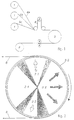
- Fig. 1 is a schematic overall structure of an inventive Device shown.
- the impregnation process if necessary starts with the bundling of small fiber bundles. These are fed from brackets 1.
- the number of small fiber bundles required depends on the desired strength of the finished fiber bundle.
- the graphic design are three small fiber bundles 6a, 6b and 6c.
- the merged fiber bundle 6 can be braked by deflecting the fiber bundle Roll 2 brought to a required tension will.
- Impregnation station which is formed in FIG. 1 as impregnation wheel 3 is.
- a molding device 4 are available with which the Fiber bundles can be reshaped to then be finished impregnated fiber bundle rolled up on a roll 5 will.
- the impregnated fiber bundle can also directly after processed after leaving the impregnation wheel.
- Impregnation wheel shows the operation of the impregnation wheel.
- the fiber bundle 6 runs on the same Speed rotating tread 35.
- the hub area is fixed.
- the first area 31 is used for heating of the incoming fiber bundle. Warm air flows there through the tread to the fiber bundle.
- the actual Impregnation takes place in the second area 32.
- There the liquid matrix material is subjected to increased pressure the tread and through the fiber bundle to be impregnated pressed until the desired degree of impregnation ends Range is reached. Since the impregnation process takes place over a there is sufficient impregnation time available for complete impregnation. That has as a result that the required matrix pressure, which is perpendicular against the fiber bundle appears to be as small as possible can be.
- a low internal pressure also reduces the necessary Fiber bundle tension.
- the throughput increased by increasing the speed of rotation of the tread 35 will.
- the detachment process takes place in the third area 33 of the impregnated fiber bundle from the tread 35 instead of. With tempered air and increased pressure and through the given direction of withdrawal can be the fiber bundle the tread 35 leave. There is no fiber bundle in the last area 34 on the tread 35. This can be taken up again of the fiber bundle are prepared.
- the single ones Areas are to be understood as self-contained chambers, the walls of which are made from the shaped areas the fixed hub, on the other hand from the fiber bundle speed rotating tread. The required media are fed from the outside into the Chamber fed.
- the tread 35 is for the liquid Permeable and rotatable matrix material.
- the width of the tread corresponds to that of the fiber bundle obtained.
- the marginal areas are somewhat raised.
- Warmed air is in through the supply device 31a directed the area 31.
- the liquid matrix material becomes the impregnation device headed. Tempered air with increased pressure passed into the area 33 by the feed device 33a.
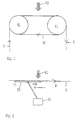
- a revolving band 45 which also consists of chain links can be built runs over two (or more) Roll 41.
- the fiber bundle 6 is from the circulating belt 45 recorded and guided past the impregnation device 42.
- the matrix material from above so first through the fiber bundle and then pressed through the contact surface.
- the contact surface is permeable to the Is matrix material.
- Fig. 5 the fiber bundle 6 with a support device 55 passed the impregnation device 42.
- the carrying device 55 initially moves at speed of the fiber bundle 6 and is then from a feedback device 56 first moved down a bit and then at high speed to the starting position back.
- a feedback device 56 By skillful control of the feedback device 56 in connection with a temporal and / or spatial control of the impregnation device 42 can be achieved be that every part of the fiber bundle is even is impregnated while supported from below.
- Fig. 6 it is generally shown how fluids one flow through homogeneous bodies.
- a homogeneous body 60 shown, which flows through from below by a fluid becomes.
- the arrows 62 indicate the direction of flow and correspond to the impregnation device, which is a matrix material feeds.
- Arrows 61 indicate that the fluid evenly from the exit surface of the homogeneous body 60 emerges, since it covers its entire volume has a homogeneous penetration resistance.
- a fiber bundle 6, which is from a roving or a bracket 1 is made up of very many fibers, also known as filaments.
- filaments also known as filaments.
- These filament piles 64 lie along a fiber bundle on different Set the cross-sectional area. For impregnation this means that the penetration resistance of a Fiber bundle across its cross section for the molten Matrix material is not constant. In areas of Filament clusters the penetration resistance is high, while he is in areas 63 that have only a few filament levels exist, is rather small.
- the one to be impregnated Fiber bundle 6 becomes solid with a homogeneous one porous body 65 connected, which is part of the support device can be and to accommodate the fiber bundle and permeable to the liquid matrix material is. If you connect this body 65 firmly to the impregnating fiber bundle 6, its penetration resistance is significantly smaller and unevenly distributed, so the fiber bundle is also with a uniform Flowing through the flow front. This is due to the fact that in the fiber bundle 6 the matrix material with constant Pressure and flow rate conditions can occur. The flow front flows evenly through the fiber bundle 6, provided that this is not too thick, compared with the thickness of the homogeneous body 65.
- the body 65 or the part of the support device which receives the fiber bundle 6, must have a constant penetration resistance have greater than that of the impregnated Fiber bundle. As a result, the fiber bundle 6 becomes more radial Direction with a continuous, from the filament distribution of the fiber bundle independent, uniform matrix material flow front flows through. This is realized by the body 6 as a cylinder section with high penetration resistance is trained.
- FIGS. 6 and 7 are the flow described in FIGS. 6 and 7 of the fiber bundle to one described in FIG Impregnation wheel shown.
- the tread 35 the impregnation wheel from a homogeneous layer of a material with a high penetration resistance.
- the Tread 35 is from the inside through the liquid matrix material enforced that in the enlargement is identified by reference numeral 68.
- Through the Training of the tread 35 creates a uniform Flow front, so that the outer fiber bundle 6 evenly is flowed through. This happens regardless of whether the fiber bundle 6 an even or uneven Has thickness distribution.
Landscapes
- Engineering & Computer Science (AREA)
- Mechanical Engineering (AREA)
- Reinforced Plastic Materials (AREA)
- Moulding By Coating Moulds (AREA)
- Treatment Of Fiber Materials (AREA)
Description
- Fig. 1
- einen schematisch dargestellten Gesamtaufbau einer erfindungsgemäßen Vorrichtung;
- Fig. 2
- eine schematische Ansicht eines Imprägnierrades in einer Seitenansicht;
- Fig. 3
- eine schematische Schnittdarstellung eines Imprägnierrades;
- Fig. 4
- eine schematische Darstellung eines umlaufenden Imprägnierbandes;
- Fig. 5
- eine schematische Darstellung einer Trageinrichtung mit Rückführeinrichtung;
- Fig. 6
- eine schematische Darstellung der Durchströmung eines homogenen Körpers;
- Fig. 7
- eine schematische Darstellung der Durchströmung einer durchlässigen Trageinrichtung und
- Fig. 8
- eine schematische, teilgeschnittene Ansicht eines Imprägnierrades mit einer Ausschnittsvergrößerung.
Claims (10)
- Verfahren zur Faserbündelimprägnierung, bei dem das Faserbündel von einem Matrixwerkstoff durchtränkt wird,
dadurch gekennzeichnet,daß das Faserbündel auf eine Trageinrichtung aufgelegt wird unddaß die Trageinrichtung zusammen mit dem aufliegenden Faserbündel an einer Imprägniereinrichtung vorbeigeführt wird. - Verfahren zur Faserbündelimprägnierung nach Anspruch 1,
dadurch gekennzeichnet,daß zum Fixieren des Faserbündels eine Zugspannung auf das Faserbündel ausgeübt wird. - Verfahren zur Faserbündelimprägnierung nach einem der Ansprüche 1 bis 2,
dadurch gekennzeichnet,daß das Faserbündel vor dem Imprägniervorgang erwärmt wird. - Verfahren zur Faserbündelimprägnierung nach einem der Ansprüche 1 bis 3,
dadurch gekennzeichnet,daß der Matrixwerkstoff durch die Trageinrichtung zu dem Faserbündel geführt wird. - Vorrichtung zur Faserbündelimprägnierung mit einer Imprägniereinrichtung zur Durchtränkung des Faserbündels mit einem Matrixwerkstoff,
dadurch gekennzeichnet,daß eine Trageinrichtung zur Aufnahme des Faserbündels (6) vorgesehen ist,daß die Trageinrichtung beweglich ist und daß die Trageinrichtung im Bereich der Imprägniereinrichtung angeordnet ist. - Vorrichtung zur Faserbündelimprägnierung nach Anspruch 5,
dadurch gekennzeichnet,daß die Trageinrichtung ein Rad (3) ist, welches einen feststehenden Nabenbereich (31,32,33,34) und eine drehbare Lauffläche (35) aufweist. - Vorrichtung zur Faserbündelimprägnierung nach einem der Ansprüche 5 oder 6,
dadurch gekennzeichnet,daß die Trageinrichtung zur Aufnahme und Imprägnierung mehrerer parallel geführter Faserbündel ausgebildet ist. - Vorrichtung zur Faserbündelimprägnierung nach einem der Ansprüche 5 bis 7,
dadurch gekennzeichnet,daß mehrere Trageinrichtungen hintereinandergeschaltet sind, unddaß sich die Trageinrichtungen gegensinnig zueinander bewegen, um eine Imprägnierung von beiden Seiten des Faserbündels zu ermöglichen. - Vorrichtung zur Faserbündelimprägnierung, bei welcher das Faserbündel von einem Matrixwerkstoff durchtränkt wird,
dadurch gekennzeichnet,daß eine Trageinrichtung zur Aufnahme des Faserbündels (6) vorgesehen ist,daß der zur Aufnahme des Faserbündels (6) ausgebildete Bereich (35, 45, 55, 65) der Trageinrichtung für den Matrixwerkstoff durchlässig ist,daß dieser Bereich (35, 45, 55, 65) homogen ausgebildet ist, so daß der Durchdringungswiderstand für den Matrixwerkstoff konstant ist, unddaß dieser Bereich (35, 45, 55, 65) einen für den Matrixwerkstoff hohen Durchdringungswiderstand aufweist, der insbesondere höher ist als der des aufgelegten Faserbündels (6). - Vorrichtung zur Faserbündelimprägnierung nach Anspruch 9,
dadurch gekennzeichnet,daß der zur Aufnahme des Faserbündels, ausgebildete, für den Matrixwerkstoff durchlässige Bereich der Trageinrichtung als ein Zylinderabschnitt mit hohem Durchdringungswiderstand ausgebildet ist.
Applications Claiming Priority (3)
| Application Number | Priority Date | Filing Date | Title |
|---|---|---|---|
| DE4413501A DE4413501A1 (de) | 1994-04-19 | 1994-04-19 | Verfahren und Vorrichtung zur Faserbündelimprägnierung |
| DE4413501 | 1994-04-19 | ||
| PCT/EP1995/001476 WO1995028266A1 (de) | 1994-04-19 | 1995-04-19 | Verfahren und vorrichtung zur faserbündelimprägnierung |
Publications (2)
| Publication Number | Publication Date |
|---|---|
| EP0756536A1 EP0756536A1 (de) | 1997-02-05 |
| EP0756536B1 true EP0756536B1 (de) | 1998-09-09 |
Family
ID=6515817
Family Applications (1)
| Application Number | Title | Priority Date | Filing Date |
|---|---|---|---|
| EP95917339A Expired - Lifetime EP0756536B1 (de) | 1994-04-19 | 1995-04-19 | Verfahren und vorrichtung zur faserbündelimprägnierung |
Country Status (7)
| Country | Link |
|---|---|
| US (1) | US5834056A (de) |
| EP (1) | EP0756536B1 (de) |
| JP (1) | JP3685335B2 (de) |
| AT (1) | ATE170795T1 (de) |
| DE (2) | DE4413501A1 (de) |
| ES (1) | ES2123248T3 (de) |
| WO (1) | WO1995028266A1 (de) |
Families Citing this family (19)
| Publication number | Priority date | Publication date | Assignee | Title |
|---|---|---|---|---|
| DE10137924B4 (de) | 2001-08-07 | 2005-12-01 | Ticona Gmbh | Langfaserverstärkte Polyolefin-Kunststoff Struktur, Verfahren zu seiner Herstellung und daraus hergestellte Formkörper |
| DE10209420A1 (de) * | 2002-03-05 | 2003-09-18 | Ticona Gmbh | Langfaserverstärkte thermoplastische Kunststoffstrukturen |
| US20050107513A1 (en) * | 2002-03-05 | 2005-05-19 | Nicolai Papke | Polyoxymethylene molding compound and molded body produced therefrom |
| DE10319237A1 (de) * | 2003-04-30 | 2004-12-02 | Ticona Gmbh | Pultrusionsverfahren und damit hergestellte Artikel |
| DE102005040620A1 (de) * | 2004-10-11 | 2006-04-13 | Bayer Materialscience Ag | Glasfaserverstärkte Polymer-Zusammensetzungen |
| WO2008024975A2 (en) * | 2006-08-25 | 2008-02-28 | Ticona Llc | Process for forming improved fiber reinforced composites and composites therefrom |
| WO2008048266A1 (en) | 2006-10-20 | 2008-04-24 | Ticona Llc | Polyether ether ketone/ polyphenylene sulfide blend |
| JP4950308B2 (ja) * | 2007-02-15 | 2012-06-13 | ダウ グローバル テクノロジーズ エルエルシー | 熱可塑性プラスチック繊維濃縮物の製法および物品 |
| JP5588872B2 (ja) * | 2007-10-22 | 2014-09-10 | スティロン ヨーロッパ ゲゼルシャフト ミット ベシュレンクテル ハフツング | 物品を成形するためのポリマー組成物及び方法 |
| JP5491767B2 (ja) * | 2009-05-26 | 2014-05-14 | パナソニック株式会社 | プリント配線板用プリプレグの製造方法及びプリント配線板用プリプレグ製造装置 |
| MX344215B (es) | 2010-10-14 | 2016-12-07 | Celanese Sales Germany Gmbh | Polioximetileno reforzado con fibra de vidrio acoplada. |
| EP2581408B1 (de) | 2011-10-14 | 2015-07-29 | Ticona GmbH | Tribologisch modifiziertes glasfaserverstärktes Polyoxymethylen |
| EP2647666A1 (de) | 2012-04-05 | 2013-10-09 | Ticona GmbH | Tribologisch modifiziertes Polyoxymethylen |
| EP2653497B1 (de) | 2012-04-17 | 2015-01-28 | Ticona GmbH | Wasserbeständige Polyoxymethylen-Zusammensetzungen |
| US9062183B2 (en) | 2012-12-20 | 2015-06-23 | Ticona Gmbh | Fiber reinforced polyoxymethylene composition with improved thermal properties |
| DE102014104869A1 (de) | 2014-04-04 | 2015-10-29 | Hans-Peter Meyerhoff | Biomaterialverbundwerkstoff |
| CN108368325A (zh) | 2015-09-30 | 2018-08-03 | 塞拉尼斯销售德国有限公司 | 低摩擦无刺耳音的组合件 |
| DE102022116096B4 (de) | 2022-06-28 | 2025-08-28 | Leibniz-Institut für Verbundwerkstoffe GmbH | Verfahren und Vorrichtung zur Schmelzimprägnierung von Fasern mit thermoplastischer Matrix |
| JP7751821B2 (ja) * | 2022-09-30 | 2025-10-09 | 福井県 | 熱可塑性樹脂プリプレグシートの製造方法および製造装置 |
Family Cites Families (5)
| Publication number | Priority date | Publication date | Assignee | Title |
|---|---|---|---|---|
| US3157536A (en) * | 1962-07-20 | 1964-11-17 | Eastman Kodak Co | Apparatus for applying plasticizer to filter tow |
| CH439205A (de) * | 1964-08-06 | 1967-07-15 | Ciba Geigy | Verfahren und Einrichtung zum Tränken von strangförmigem Material |
| US4494436A (en) * | 1983-09-02 | 1985-01-22 | Elfin Corporation | Apparatus for manufacturing resin impregnated fiber braided products |
| US4640861A (en) * | 1984-06-07 | 1987-02-03 | E. I. Du Pont De Nemours And Company | Fiber reinforced thermoplastic material |
| US4968534A (en) * | 1989-01-17 | 1990-11-06 | Npd Corp. | Method and apparatus for pattern impregnation of a porous web |
-
1994
- 1994-04-19 DE DE4413501A patent/DE4413501A1/de not_active Withdrawn
-
1995
- 1995-04-19 US US08/722,152 patent/US5834056A/en not_active Expired - Lifetime
- 1995-04-19 JP JP52673795A patent/JP3685335B2/ja not_active Expired - Fee Related
- 1995-04-19 DE DE59503528T patent/DE59503528D1/de not_active Expired - Lifetime
- 1995-04-19 WO PCT/EP1995/001476 patent/WO1995028266A1/de not_active Ceased
- 1995-04-19 AT AT95917339T patent/ATE170795T1/de not_active IP Right Cessation
- 1995-04-19 EP EP95917339A patent/EP0756536B1/de not_active Expired - Lifetime
- 1995-04-19 ES ES95917339T patent/ES2123248T3/es not_active Expired - Lifetime
Also Published As
| Publication number | Publication date |
|---|---|
| DE4413501A1 (de) | 1995-10-26 |
| US5834056A (en) | 1998-11-10 |
| ATE170795T1 (de) | 1998-09-15 |
| WO1995028266A1 (de) | 1995-10-26 |
| DE59503528D1 (de) | 1998-10-15 |
| JPH09512495A (ja) | 1997-12-16 |
| ES2123248T3 (es) | 1999-01-01 |
| JP3685335B2 (ja) | 2005-08-17 |
| EP0756536A1 (de) | 1997-02-05 |
Similar Documents
| Publication | Publication Date | Title |
|---|---|---|
| DE3888252T2 (de) | Verfahren zur kontinuierlichen Herstellung faserverstärkter thermoplastischer Prepregs und Vorrichtung zur Durchführung desselben. | |
| EP0756536A1 (de) | Verfahren und vorrichtung zur faserbündelimprägnierung | |
| DE19523490C2 (de) | Vorrichtung und Verfahren zur Imprägnierung von Fasersträngen mit Kunststoffmaterial | |
| DE4408637C2 (de) | Verfahren zur Herstellung eines mit einem Faserverbundwerkstoff verstärkten Körpers | |
| EP1149215B1 (de) | Verfahren zur herstellung eines flachbandes | |
| DE102011010330B4 (de) | Extrusionswerkzeug | |
| EP1042110B1 (de) | Verfahren und vorrichtung zur faserimprägnierung | |
| DE2848157A1 (de) | Vorrichtung zum aufbringen von fluessigkeit auf ein gewebe | |
| DE69429736T2 (de) | Verfahren zum herstellen von langfaserverstärkten harzzusammensetzungen | |
| DE102017220330B4 (de) | Einrichtung und Verfahren zum Herstellen eines Tow-Prepregs | |
| EP3470196B1 (de) | Einrichtung und verfahren zur imprägnierung von faserbündeln mit einer polymerschmelze | |
| DE202020101503U1 (de) | Druckkopf mit zumindest einer Zuführung für ein aufschmelzbares Filament sowie ein mit einem additiven Herstellungsverfahren hergestellter Körper | |
| DE102019116694A1 (de) | Fördereinrichtung und Arbeitskopf für eine additive Fertigungsmaschine sowie additive Fertigungsmaschine | |
| DE2755516A1 (de) | Verfahren und maschine zur kontinuierlichen herstellung einer unverwebten netzstruktur | |
| DE69313957T2 (de) | Vorrichtung zum Kräuseln eines Faserstranges und zum Aufbringen von Finish auf den Faserstrang | |
| DE102014106460A1 (de) | Textilmaschine | |
| DE2654809C2 (de) | Vorrichtung zum Aufbringen von flüssigem Harz auf Faserstränge | |
| DE10023544C1 (de) | Verfahren zur Herstellung von Produkten aus polymeren Werkstoffen, in die Festigkeitsträger eingebettet sind | |
| DE2430576A1 (de) | Mehrschichtfasermatte | |
| EP1188859B1 (de) | Elastische Walze | |
| EP1057928B1 (de) | Elastische Walze und Verfahren zum Herstellen einer solchen | |
| EP1140459A1 (de) | Verfahren zur herstellung eines compounds aus einem fliessfähigen kunststoff und einer festen fasereinlage durch extrudieren und vorrichtung zur durchführung des verfahrens | |
| DE102022116096B4 (de) | Verfahren und Vorrichtung zur Schmelzimprägnierung von Fasern mit thermoplastischer Matrix | |
| DE102021113831A1 (de) | Verfahren und Vorrichtung zur Herstellung von endlosen Bändern mit additiven Herstellungsverfahren | |
| DE3903962C2 (de) | Vorrichtung zum kontinuierlichen Herstellen von Profildrähten aus strangförmigen metallischen Halbzeugen |
Legal Events
| Date | Code | Title | Description |
|---|---|---|---|
| PUAI | Public reference made under article 153(3) epc to a published international application that has entered the european phase |
Free format text: ORIGINAL CODE: 0009012 |
|
| 17P | Request for examination filed |
Effective date: 19961017 |
|
| AK | Designated contracting states |
Kind code of ref document: A1 Designated state(s): AT BE CH DE DK ES FR GB GR IE IT LI NL PT SE |
|
| GRAG | Despatch of communication of intention to grant |
Free format text: ORIGINAL CODE: EPIDOS AGRA |
|
| GRAG | Despatch of communication of intention to grant |
Free format text: ORIGINAL CODE: EPIDOS AGRA |
|
| GRAH | Despatch of communication of intention to grant a patent |
Free format text: ORIGINAL CODE: EPIDOS IGRA |
|
| 17Q | First examination report despatched |
Effective date: 19980128 |
|
| GRAH | Despatch of communication of intention to grant a patent |
Free format text: ORIGINAL CODE: EPIDOS IGRA |
|
| GRAA | (expected) grant |
Free format text: ORIGINAL CODE: 0009210 |
|
| AK | Designated contracting states |
Kind code of ref document: B1 Designated state(s): AT BE CH DE DK ES FR GB GR IE IT LI NL PT SE |
|
| PG25 | Lapsed in a contracting state [announced via postgrant information from national office to epo] |
Ref country code: GR Free format text: LAPSE BECAUSE OF NON-PAYMENT OF DUE FEES Effective date: 19980909 |
|
| REF | Corresponds to: |
Ref document number: 170795 Country of ref document: AT Date of ref document: 19980915 Kind code of ref document: T |
|
| REG | Reference to a national code |
Ref country code: CH Ref legal event code: EP |
|
| REF | Corresponds to: |
Ref document number: 59503528 Country of ref document: DE Date of ref document: 19981015 |
|
| REG | Reference to a national code |
Ref country code: CH Ref legal event code: NV Representative=s name: BUECHEL, VON REVY & PARTNER |
|
| ET | Fr: translation filed | ||
| REG | Reference to a national code |
Ref country code: IE Ref legal event code: FG4D Free format text: GERMAN |
|
| PG25 | Lapsed in a contracting state [announced via postgrant information from national office to epo] |
Ref country code: DK Free format text: LAPSE BECAUSE OF FAILURE TO SUBMIT A TRANSLATION OF THE DESCRIPTION OR TO PAY THE FEE WITHIN THE PRESCRIBED TIME-LIMIT Effective date: 19981209 |
|
| PG25 | Lapsed in a contracting state [announced via postgrant information from national office to epo] |
Ref country code: PT Free format text: LAPSE BECAUSE OF FAILURE TO SUBMIT A TRANSLATION OF THE DESCRIPTION OR TO PAY THE FEE WITHIN THE PRESCRIBED TIME-LIMIT Effective date: 19981214 |
|
| GBT | Gb: translation of ep patent filed (gb section 77(6)(a)/1977) |
Effective date: 19981202 |
|
| REG | Reference to a national code |
Ref country code: ES Ref legal event code: FG2A Ref document number: 2123248 Country of ref document: ES Kind code of ref document: T3 |
|
| PLBE | No opposition filed within time limit |
Free format text: ORIGINAL CODE: 0009261 |
|
| STAA | Information on the status of an ep patent application or granted ep patent |
Free format text: STATUS: NO OPPOSITION FILED WITHIN TIME LIMIT |
|
| 26N | No opposition filed | ||
| IECL | Ie: translation for ep claims filed | ||
| IECL | Ie: translation for ep claims filed | ||
| REG | Reference to a national code |
Ref country code: GB Ref legal event code: IF02 |
|
| REG | Reference to a national code |
Ref country code: CH Ref legal event code: PUE Owner name: INSTITUT FUER VERBUNDWERKSTOFFE GMBH TRANSFER- FAC |
|
| REG | Reference to a national code |
Ref country code: GB Ref legal event code: 732E |
|
| NLS | Nl: assignments of ep-patents |
Owner name: FACT FUTURE ADVANCED COMPOSITES & TECHNOLOGY GMBH |
|
| REG | Reference to a national code |
Ref country code: FR Ref legal event code: TP |
|
| PGFP | Annual fee paid to national office [announced via postgrant information from national office to epo] |
Ref country code: ES Payment date: 20080429 Year of fee payment: 14 Ref country code: CH Payment date: 20080415 Year of fee payment: 14 |
|
| PGFP | Annual fee paid to national office [announced via postgrant information from national office to epo] |
Ref country code: AT Payment date: 20080415 Year of fee payment: 14 |
|
| PGFP | Annual fee paid to national office [announced via postgrant information from national office to epo] |
Ref country code: BE Payment date: 20080522 Year of fee payment: 14 |
|
| PGFP | Annual fee paid to national office [announced via postgrant information from national office to epo] |
Ref country code: SE Payment date: 20080414 Year of fee payment: 14 Ref country code: IE Payment date: 20080424 Year of fee payment: 14 |
|
| BERE | Be: lapsed |
Owner name: *FACT FUTURE ADVANCED COMPOSITES & TECHNOLOGY G.M. Effective date: 20090430 |
|
| REG | Reference to a national code |
Ref country code: CH Ref legal event code: PL |
|
| EUG | Se: european patent has lapsed | ||
| PG25 | Lapsed in a contracting state [announced via postgrant information from national office to epo] |
Ref country code: LI Free format text: LAPSE BECAUSE OF NON-PAYMENT OF DUE FEES Effective date: 20090430 Ref country code: CH Free format text: LAPSE BECAUSE OF NON-PAYMENT OF DUE FEES Effective date: 20090430 Ref country code: AT Free format text: LAPSE BECAUSE OF NON-PAYMENT OF DUE FEES Effective date: 20090419 |
|
| REG | Reference to a national code |
Ref country code: IE Ref legal event code: MM4A |
|
| PG25 | Lapsed in a contracting state [announced via postgrant information from national office to epo] |
Ref country code: IE Free format text: LAPSE BECAUSE OF NON-PAYMENT OF DUE FEES Effective date: 20090420 |
|
| PG25 | Lapsed in a contracting state [announced via postgrant information from national office to epo] |
Ref country code: BE Free format text: LAPSE BECAUSE OF NON-PAYMENT OF DUE FEES Effective date: 20090430 |
|
| REG | Reference to a national code |
Ref country code: ES Ref legal event code: FD2A Effective date: 20090420 |
|
| PG25 | Lapsed in a contracting state [announced via postgrant information from national office to epo] |
Ref country code: ES Free format text: LAPSE BECAUSE OF NON-PAYMENT OF DUE FEES Effective date: 20090420 |
|
| PG25 | Lapsed in a contracting state [announced via postgrant information from national office to epo] |
Ref country code: SE Free format text: LAPSE BECAUSE OF NON-PAYMENT OF DUE FEES Effective date: 20090420 |
|
| REG | Reference to a national code |
Ref country code: NL Ref legal event code: SD Effective date: 20111104 |
|
| REG | Reference to a national code |
Ref country code: DE Ref legal event code: R082 Ref document number: 59503528 Country of ref document: DE |
|
| REG | Reference to a national code |
Ref country code: FR Ref legal event code: TP Owner name: CELSTRAN GMBH, DE Effective date: 20111121 |
|
| REG | Reference to a national code |
Ref country code: GB Ref legal event code: 732E Free format text: REGISTERED BETWEEN 20111215 AND 20111221 |
|
| REG | Reference to a national code |
Ref country code: DE Ref legal event code: R081 Ref document number: 59503528 Country of ref document: DE Owner name: CELSTRAN GMBH, DE Free format text: FORMER OWNER: CEISTRAN GMBH, 65843 SULZBACH, DE Effective date: 20111222 Ref country code: DE Ref legal event code: R081 Ref document number: 59503528 Country of ref document: DE Owner name: CELSTRAN GMBH, DE Free format text: FORMER OWNER: FACT FUTURE ADVANCED COMPOSITES & TECHNOLOGY GMBH, 67657 KAISERSLAUTERN, DE Effective date: 20111207 |
|
| PGFP | Annual fee paid to national office [announced via postgrant information from national office to epo] |
Ref country code: DE Payment date: 20120425 Year of fee payment: 18 Ref country code: NL Payment date: 20120413 Year of fee payment: 18 |
|
| PGFP | Annual fee paid to national office [announced via postgrant information from national office to epo] |
Ref country code: GB Payment date: 20120418 Year of fee payment: 18 Ref country code: FR Payment date: 20120504 Year of fee payment: 18 |
|
| PGFP | Annual fee paid to national office [announced via postgrant information from national office to epo] |
Ref country code: IT Payment date: 20120420 Year of fee payment: 18 |
|
| REG | Reference to a national code |
Ref country code: NL Ref legal event code: V1 Effective date: 20131101 |
|
| GBPC | Gb: european patent ceased through non-payment of renewal fee |
Effective date: 20130419 |
|
| PG25 | Lapsed in a contracting state [announced via postgrant information from national office to epo] |
Ref country code: GB Free format text: LAPSE BECAUSE OF NON-PAYMENT OF DUE FEES Effective date: 20130419 Ref country code: DE Free format text: LAPSE BECAUSE OF NON-PAYMENT OF DUE FEES Effective date: 20131101 |
|
| REG | Reference to a national code |
Ref country code: FR Ref legal event code: ST Effective date: 20131231 |
|
| REG | Reference to a national code |
Ref country code: DE Ref legal event code: R119 Ref document number: 59503528 Country of ref document: DE Effective date: 20131101 |
|
| PG25 | Lapsed in a contracting state [announced via postgrant information from national office to epo] |
Ref country code: FR Free format text: LAPSE BECAUSE OF NON-PAYMENT OF DUE FEES Effective date: 20130430 Ref country code: NL Free format text: LAPSE BECAUSE OF NON-PAYMENT OF DUE FEES Effective date: 20131101 Ref country code: IT Free format text: LAPSE BECAUSE OF NON-PAYMENT OF DUE FEES Effective date: 20130419 |