EP0756902A1 - Dispositif de nettoyage à haute pression - Google Patents
Dispositif de nettoyage à haute pression Download PDFInfo
- Publication number
- EP0756902A1 EP0756902A1 EP96112065A EP96112065A EP0756902A1 EP 0756902 A1 EP0756902 A1 EP 0756902A1 EP 96112065 A EP96112065 A EP 96112065A EP 96112065 A EP96112065 A EP 96112065A EP 0756902 A1 EP0756902 A1 EP 0756902A1
- Authority
- EP
- European Patent Office
- Prior art keywords
- switch
- pressure
- cleaning device
- actuating element
- pressure cleaning
- Prior art date
- Legal status (The legal status is an assumption and is not a legal conclusion. Google has not performed a legal analysis and makes no representation as to the accuracy of the status listed.)
- Granted
Links
- 238000004140 cleaning Methods 0.000 title claims abstract description 51
- 239000007788 liquid Substances 0.000 claims abstract description 27
- 238000006073 displacement reaction Methods 0.000 claims description 7
- 239000012530 fluid Substances 0.000 description 3
- 238000011144 upstream manufacturing Methods 0.000 description 3
- 230000006835 compression Effects 0.000 description 2
- 238000007906 compression Methods 0.000 description 2
- 238000010276 construction Methods 0.000 description 2
- 238000005452 bending Methods 0.000 description 1
- 230000001419 dependent effect Effects 0.000 description 1
- 230000000694 effects Effects 0.000 description 1
- 238000010438 heat treatment Methods 0.000 description 1
- 230000002093 peripheral effect Effects 0.000 description 1
- 238000005086 pumping Methods 0.000 description 1
Images


Classifications
-
- F—MECHANICAL ENGINEERING; LIGHTING; HEATING; WEAPONS; BLASTING
- F04—POSITIVE - DISPLACEMENT MACHINES FOR LIQUIDS; PUMPS FOR LIQUIDS OR ELASTIC FLUIDS
- F04B—POSITIVE-DISPLACEMENT MACHINES FOR LIQUIDS; PUMPS
- F04B49/00—Control, e.g. of pump delivery, or pump pressure of, or safety measures for, machines, pumps, or pumping installations, not otherwise provided for, or of interest apart from, groups F04B1/00 - F04B47/00
- F04B49/02—Stopping, starting, unloading or idling control
- F04B49/022—Stopping, starting, unloading or idling control by means of pressure
-
- B—PERFORMING OPERATIONS; TRANSPORTING
- B08—CLEANING
- B08B—CLEANING IN GENERAL; PREVENTION OF FOULING IN GENERAL
- B08B3/00—Cleaning by methods involving the use or presence of liquid or steam
- B08B3/02—Cleaning by the force of jets or sprays
- B08B3/026—Cleaning by making use of hand-held spray guns; Fluid preparations therefor
-
- H—ELECTRICITY
- H01—ELECTRIC ELEMENTS
- H01H—ELECTRIC SWITCHES; RELAYS; SELECTORS; EMERGENCY PROTECTIVE DEVICES
- H01H35/00—Switches operated by change of a physical condition
- H01H35/24—Switches operated by change of fluid pressure, by fluid pressure waves, or by change of fluid flow
-
- H—ELECTRICITY
- H01—ELECTRIC ELEMENTS
- H01H—ELECTRIC SWITCHES; RELAYS; SELECTORS; EMERGENCY PROTECTIVE DEVICES
- H01H3/00—Mechanisms for operating contacts
-
- H—ELECTRICITY
- H01—ELECTRIC ELEMENTS
- H01H—ELECTRIC SWITCHES; RELAYS; SELECTORS; EMERGENCY PROTECTIVE DEVICES
- H01H9/00—Details of switching devices, not covered by groups H01H1/00 - H01H7/00
- H01H9/20—Interlocking, locking, or latching mechanisms
Definitions
- the invention relates to a high-pressure cleaning device with an electric motor, a high-pressure pump driven by the latter and with an automatic switch-off for the electric motor, which comprises a switch which can be switched by an actuating element which can be moved depending on the pressure or the flow of the liquid conveyed by the high-pressure pump.
- Such a high-pressure pump is described, for example, in DE 42 21 286 A1.
- the known switch-off device comprises a displaceably mounted plunger, which acts on a microswitch and actuates it in such a way that the current supply to the electric motor is interrupted when certain pressure or flow conditions occur, for example when the liquid supply is prevented by closing the discharge line or when the pump not enough liquid is added.
- the microswitch used as an emergency switch is in this construction connected in series with the main switch of the high-pressure cleaning device, so an additional main switch is required for the usual switch-off of the device.
- the emergency stop switch is therefore also used directly as the main switch in the new design, so that it is no longer necessary to provide separate switches for these functions.
- This common switch which performs both the emergency shutdown and the main shutdown, is still actuated by the mechanical actuating element, which is moved depending on the flow or pressure and can lead to an emergency shutdown if corresponding maximum values are exceeded.
- a switch-off element acts on the same switch, which can move the same switch into the switch-off position, independently from the respective position of the actuating element. This means that the device can be switched off at any time using this switch-off element, a special switch is no longer necessary.
- the switch-off element it would be possible for the switch-off element to act directly on the actuating element and to move it independently of the pressure and flow values, but a construction is advantageous in which both the actuation element and the switch-off element are movable against a movable switching element of the switch and in which the switching element is moved to the off position of the switch.
- Actuating element and switch-off element are thus parallel switching elements, which can alternatively move the switch into the switch-off position.
- both the actuating element and the switch-off element are so far removed from the switch that the switch is not switched off. As soon as the maximum values of pressure or flow of the liquid are exceeded, the actuating element is moved against the switch and switches it off, the actuating element is actuated, this has the same effect on the switch.
- the switch-off element can be fixed in the switch-off position, for example by latching the switch-off element. This ensures that this consciously set position is maintained, that is, the device remains switched off when the switch-off element is moved into the switch-off position.
- the switch-off element moves the switch between two positions and the actuating element only reaches the switch for switching in one of these two positions. So the switch is shifted so far by the switch-off element that the actuating element can no longer actuate the switch, only when the switch is brought closer to the actuating element by the switch-off element is switching of the switch by the actuating element possible at all. If the switch is not actuated, the motor is switched off, the motor only runs when the switch is actuated.
- the switch on the high-pressure cleaning device is pivotally mounted and if the switch-off element pivots the switch between two positions.
- the switch is pressed by a spring against the actuating element.
- the switch-off element is a rotatable eccentric.
- the actuating element is a swivel lever which bears against a switching projection of the switch and which can be swiveled by a plunger which is displaceable as a function of the pressure or the flow of the conveyed liquid. This allows the movement of the plunger to be deflected, for example the displacement of the switching element of the switch transversely to the displacement of the plunger.
- the actuating element carries a button that can be placed on the switching element of the switch and can be displaced depending on the pressure or the flow of the liquid conveyed such that the button actuates the switching element in one position and not in another, and that the actuating element can also be moved by hand in such a way that the button can only be applied to the switching element in one position.
- the switching element itself is therefore moved to a permanent switch-off in a position in which the button of the switching element cannot reach the switch, so that no switching operation can occur even when the actuating element is displaced under the influence of the pressure or the flow of the cleaning liquid.
- the actuating element can be rotated about an axis of rotation and can be displaced along the axis of rotation depending on the pressure or the flow of the cleaning liquid and if there is a different distance in the axial direction on its outer circumference, which extends only over a limited circumferential angle the button with the axis of rotation.
- the button can actuate the switching element of the switch by axially displacing the actuating element, in another angular position, however, the button cannot be placed on the switching element of the switch, regardless of the respective axial position of the actuating element.
- the actuating element is connected in a rotationally fixed and axially freely displaceable manner to a switching element designed as a rotating element.
- a particularly preferred embodiment is characterized in that the actuating element is designed as a sleeve into which a pin of the switch-off element protrudes, that a plunger depending on the pressure or flow of the cleaning fluid rests on the bottom of the sleeve and that there is a between the switch-off element and the sleeve this is arranged against the plunger spring.
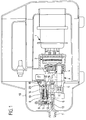
- FIG. 1 shows a high-pressure cleaning device which essentially comprises an electric motor 1, a swash plate drive 2 driven by it and an axial piston pump 3 driven by the swash plate drive 2.
- the pistons 4 of the axial piston pump 3 are pressed against the swash plate drive 2 by springs and moved reciprocally into the pumping chambers 5.
- Cleaning fluid drawn in by the axial piston pump 3 is conveyed through a pressure line 6 emerging from the axial piston pump 3 and discharged via a connection 7 to which, for example, a high pressure hose with a high pressure lance can be connected, these parts are not shown in the drawing.
- a piston 9 is sealed and displaceably mounted in a separate control chamber 8 of the axial piston pump and is acted upon by a spring 10 arranged in the control chamber 8.
- the piston 9 separates the control chamber 8 into two chambers, namely a first chamber 11, which is connected via a control line 12 to an injector-like constriction 13 of the pressure line 6, and into a chamber 14, which is upstream in a manner not clearly visible from the drawing the constriction 13 is connected to the pressure line 6.
- a first chamber 11 which is connected via a control line 12 to an injector-like constriction 13 of the pressure line 6, and into a chamber 14, which is upstream in a manner not clearly visible from the drawing the constriction 13 is connected to the pressure line 6.
- the pressures prevail in the chambers 11 and 14, which are respectively set in the region of the constriction 13 and in the region of the pressure line 6 arranged upstream.
- the piston 9 is provided with a plunger 15, which is sealed out of the control chamber 8 and faces the switching tongue 16 of a microswitch 17; this microswitch 17 is attached to the axial piston pump 3 in a suitable manner, not shown in the drawing.
- a rotatable switch-off element 18 is mounted on the axial piston pump 3 and can be rotated from the outside of the high-pressure cleaning device.
- this switch-off element 18 can be provided with a switching shaft, which is led out of a housing 19 of the high-pressure cleaning device, this is not shown in the drawing.
- the switch-off element 18 carries a lateral projection 20 which, when the switch-off element 18 is in a first angular position, is removed from the switching tongue 16 of the microswitch 17 (FIG. 2) but bears against the switching tongue 16 in another angular position and thereby actuates the microswitch 17 (FIG. 3). , that is, the microswitch 17 thereby interrupts the power supply to the electric motor 1.
- the switch-off element 18 is arranged next to the plunger 15 in such a way that both the switch-off element 18 and the plunger 15 can move the same switching tongue 16 into the switch-off position of the microswitch 17. If the switch-off element 18 moves the microswitch 17 into the switch-off position, the switch-off element 18 is fixed in this switch-off position; this can be done, for example, by an elastic catch, by means of which the rotary movement of the switch-off element 18 is rasterized. This notch is not shown in the drawing.
- the operator When operating the high-pressure cleaning device, the operator first switches the switch-off element 18 from the switch-off position (FIG. 3) to the operating position (FIG. 2). The device is thus switched on, but the electric motor 1 will only start to run when a pressure difference has built up in the chambers 11 and 14, that is to say when the plunger 15 has also been moved into the retracted position.
- the microswitch 17 is switched exclusively by the plunger 15, since the switch-off element 18 acts as a switch and remains switched on. However, if the user wants to shut down the device at the end of operation, he can achieve this in a simple manner via the switch-off element 18; it is then sufficient to turn the switch-off element 18 into the switch-off position.
- the plunger 15 can also be moved in another way for emergency shutdown.
- the plunger is switched by a pressure difference in the pressure line; in principle, it would also be possible to provide other switching variables for actuating the plunger 15, for example the plunger could be shifted depending on the temperature in order to enable a shutdown in the event of excessive heating of the liquid , other possibilities are also conceivable.
- the only decisive factor is that, in addition to the operational displacement of the plunger or another actuating element of the microswitch 17, an additional manual switch-off option for the same switch is provided.
- both the actuating element and the switch-off element act on a common switching tongue 16 of the switch.
- the actuating element only switches depending on the pressure or flow of the cleaning liquid when the switch-off element of the switch is in a position, but not when the switch-off element is in a different position.
- the high-pressure cleaning device itself can be constructed in the same way as in the exemplary embodiment in FIGS. 1 to 3, and parts which correspond to one another therefore have the same reference symbols.
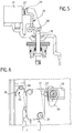
- the microswitch 17 is mounted on the high-pressure cleaning device so that it can rotate about an axis of rotation 21.
- a V-shaped spiral spring 22 rests with one arm 23 on the microswitch 17 and with the other arm 24 on the high-pressure cleaning device itself and thereby swivels the microswitch 17 against a stop, not shown in the drawing. In this position, which is shown in solid lines in FIG. 6, the switch is in its actuating position.
- a swivel lever 25 is pivotably mounted on the high-pressure cleaning device, one arm 26 of which lies opposite a switching element 27 which can be pressed resiliently into the microswitch 17, and a plunger 15 bears against the other arm 28, which in the same way as the plunger 15 in the exemplary embodiment of FIGS Depending on the pressure and / or flow of the liquid to be pumped is displaceable, however in the exemplary embodiment shown here in the opposite direction, that is to say in contrast to the exemplary embodiment in FIGS. 1 to 3, the motor is switched off in this exemplary embodiment when the tappet enters the high-pressure cleaning device is retracted, that is removed from the pivot lever 25. However, if the plunger 15 is advanced, it pivots the pivot lever 25 and presses it with its arm 26 against the switching element 27, care being taken that the spiral spring 22 is so strong that it prevents the microswitch 17 from evading.
- An eccentric 30 is rotatably mounted on the high-pressure cleaning device by means of a rotary handle 29, which is removed from the microswitch 17 in one position, but in the second position, which is shown in broken lines in FIG. 6, but comes into contact with the microswitch 17 and this counteracts the action of Bending spring 22 is pivoted so far that the pivot lever 25 can no longer reach the switching element 27 in any position which it assumes due to the displacement of the plunger 15. The switching element 27 therefore remains unactuated in this pivoted position of the microswitch 17, and this leads to the motor remaining permanently switched off.
- the rotary handle 29 thus forms, together with the eccentric 30, a switch-off element with which the motor can be switched off permanently, while in the operating state the motor can be switched off depending on the pressure or the flow of the liquid via the plunger 15 and the pivot lever 25.
- the motor is switched on and off depending on the pressure or the flow of the liquid on the one hand, and the motor is switched on and off at the beginning and at the end of the operating phase via a single microswitch 17.
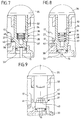
- the microswitch 17 is held firmly on the high-pressure cleaning device here, directly next to the microswitch 17, a sleeve-shaped actuating element 31 is mounted axially displaceably on the high-pressure cleaning device transversely to the direction of displacement of the switching element 27 of the microswitch 17.
- the sleeve-shaped actuating element 31 is surrounded on its top and on its underside by a cylindrical guide 32 or 33, which, in addition to the limited axial displaceability of the actuating element 31, also rotatably supports it about its longitudinal axis.
- a pin 34 of a rotary handle 35 arranged on the high-pressure cleaning device projects into the sleeve-shaped actuating element 31, which together with the pin 34 forms the switch-off element of this arrangement.
- the pin 34 is axially freely displaceable and non-rotatably connected to the sleeve-shaped actuating element 31, so that when the rotary handle 35 is rotated, the sleeve-shaped actuating element 31 is also rotated about its axis of rotation.
- a compression spring 38 is arranged, which presses the sleeve-shaped actuating element 31 against a plunger 15, which bears against the underside of the bottom 37 and in the direction of the axis of rotation of the actuating element 31 in Depending on the pressure or on the flow of the liquid being pumped.
- the sleeve-shaped actuating element 31 carries a switching cam 39 on its circumference, which extends in the circumferential direction only over a small angular range and which also has a limited extent in the axial direction.
- the surface of the switching cam 39 which is furthest away from the axis of rotation forms a button 40 which merges into the peripheral surface of the sleeve-shaped actuating element 31 via an oblique sliding surface 41.
- the switching cam 39 can be moved by axially displacing the actuating element 31 into a position in which the button 40 rests on the switching element 27 and presses it into the microswitch 17 (FIG. 7) , and in a position in which the switching cam 39 lies next to the switching element 27 and thus does not actuate it (FIG. 8).
- This shift between the switched-on position and the switched-off position takes place against the action of the compression spring 38 by the plunger 15, which moves depending on the pressure or the flow of the liquid. It is therefore possible to switch the motor on or off depending on the pressure or the flow of the liquid.
- the button 40 of the switching cam 39 can in no case actuate the switching element 27 of the microswitch 17, regardless of the respective axial position of the sleeve-shaped actuating element 31. This ensures in this angular position of the actuating element 31 that the microswitch 17 is not can be switched, this is the switch-off position of the device.
Landscapes
- Engineering & Computer Science (AREA)
- Mechanical Engineering (AREA)
- General Engineering & Computer Science (AREA)
- Physics & Mathematics (AREA)
- Fluid Mechanics (AREA)
- Cleaning By Liquid Or Steam (AREA)
- Switches Operated By Changes In Physical Conditions (AREA)
- Cyclones (AREA)
- Encapsulation Of And Coatings For Semiconductor Or Solid State Devices (AREA)
- Electrical Discharge Machining, Electrochemical Machining, And Combined Machining (AREA)
Applications Claiming Priority (2)
| Application Number | Priority Date | Filing Date | Title |
|---|---|---|---|
| DE19527854 | 1995-07-29 | ||
| DE19527854A DE19527854C1 (de) | 1995-07-29 | 1995-07-29 | Hochdruckreinigungsgerät |
Publications (2)
| Publication Number | Publication Date |
|---|---|
| EP0756902A1 true EP0756902A1 (fr) | 1997-02-05 |
| EP0756902B1 EP0756902B1 (fr) | 1999-01-13 |
Family
ID=7768166
Family Applications (1)
| Application Number | Title | Priority Date | Filing Date |
|---|---|---|---|
| EP96112065A Expired - Lifetime EP0756902B1 (fr) | 1995-07-29 | 1996-07-26 | Dispositif de nettoyage à haute pression |
Country Status (7)
| Country | Link |
|---|---|
| US (1) | US6062822A (fr) |
| EP (1) | EP0756902B1 (fr) |
| AT (1) | ATE175595T1 (fr) |
| BR (1) | BR9609949A (fr) |
| DE (1) | DE19527854C1 (fr) |
| DK (1) | DK0756902T3 (fr) |
| WO (1) | WO1997004888A1 (fr) |
Cited By (3)
| Publication number | Priority date | Publication date | Assignee | Title |
|---|---|---|---|---|
| WO2001031200A3 (fr) * | 1999-10-22 | 2002-03-14 | Wagner Spray Tech Corp | Pompe a piston |
| US6419456B1 (en) | 1999-10-22 | 2002-07-16 | Wagner Spray Tech Corporation | Switch for controlling the motor of a piston pump |
| US6435846B1 (en) | 1999-10-22 | 2002-08-20 | Wagner Spray Tech Corporation | Piston pump having housing with a pump housing and a pump assembly drive housing formed therein |
Families Citing this family (16)
| Publication number | Priority date | Publication date | Assignee | Title |
|---|---|---|---|---|
| US5953352A (en) * | 1997-06-23 | 1999-09-14 | Micron Electronics, Inc. | Method of checking data integrity for a raid 1 system |
| DE10053248A1 (de) * | 2000-10-26 | 2002-05-08 | Kaercher Gmbh & Co Alfred | Hochdruckreinigungsgerät |
| DE102004063201A1 (de) * | 2004-12-23 | 2006-07-06 | Alfred Kärcher Gmbh & Co. Kg | Flächenreinigungsgerät |
| US7071429B1 (en) * | 2005-09-23 | 2006-07-04 | Anderson Richard P | Linear adjustment operator for pressure control of paint pumps |
| US8038413B2 (en) * | 2006-07-17 | 2011-10-18 | Briggs And Stratton Corporation | Idle down control for a pressure washer |
| US20090317262A1 (en) * | 2006-07-17 | 2009-12-24 | Briggs & Stratton Corporation | Engine speed control for pressure washer |
| US20100282862A1 (en) * | 2009-05-06 | 2010-11-11 | Briggs & Stratton Corporation | Pressure washer with throttle control |
| US20110142685A1 (en) * | 2009-12-16 | 2011-06-16 | Briggs & Strantton Corporation | Pump unloader valve and engine throttle system |
| CN102208289B (zh) * | 2010-03-29 | 2013-06-26 | 香港尚德-富佑捷有限公司 | 开关装置及其制作和使用方法 |
| JP6046333B2 (ja) * | 2011-04-14 | 2016-12-14 | リョービ株式会社 | 高圧洗浄機 |
| DE202011005630U1 (de) * | 2011-04-27 | 2014-02-07 | Nilfisk-Advance A/S | Regelsicherheitsblock für Hochdruck-Reinigungsgeräte mit Schalteinrichtung |
| CN102755971B (zh) * | 2012-07-18 | 2014-05-07 | 梁福根 | 高压清洗机气囊球压力控制器 |
| CN105435986A (zh) * | 2015-12-19 | 2016-03-30 | 台州市正茂动力工具有限公司 | 一种高压清洗机关枪停机装置 |
| CN106040643B (zh) * | 2016-06-15 | 2018-05-29 | 惠安县云点网络科技有限公司 | 一种带有自动清洁的电力启动装置 |
| CN107234082B (zh) * | 2017-05-10 | 2019-08-23 | 浙江光跃环保科技股份有限公司 | 一种便捷的生化仪器清洗设备 |
| CN110891700B (zh) * | 2017-08-16 | 2022-05-13 | 阿尔弗雷德·卡赫欧洲两合公司 | 高压清洗机 |
Citations (3)
| Publication number | Priority date | Publication date | Assignee | Title |
|---|---|---|---|---|
| DE1806598A1 (de) * | 1968-11-02 | 1970-05-14 | Stiebel Werke Gmbh & Co Dr | Elektrischer Zweistufenschalter fuer einen elektrischen Durchlauferhitzer |
| US4247260A (en) * | 1978-03-13 | 1981-01-27 | Siemens Aktiengesellschaft | Pressure regulated water supply system |
| DE4221286A1 (de) | 1991-07-05 | 1993-01-07 | Annovi & Reverberi S P A | Vorrichtung zur automatischen ein- und ausschaltung eines motor-pumpen-aggregats fuer wasserreinigungsmaschinen |
Family Cites Families (4)
| Publication number | Priority date | Publication date | Assignee | Title |
|---|---|---|---|---|
| US3563671A (en) * | 1969-10-01 | 1971-02-16 | Weber Ind Inc | Pump control |
| US3739810A (en) * | 1971-12-09 | 1973-06-19 | Jacuzzi Bros Inc | Pressure controlled water system with isolatable pressure switch |
| US3782858A (en) * | 1972-10-24 | 1974-01-01 | Red Jacket Mfg Co | Control apparatus for a water supply system |
| JPS5828436B2 (ja) * | 1973-11-30 | 1983-06-15 | 株式会社日立製作所 | ジドウシキポンプ |
-
1995
- 1995-07-29 DE DE19527854A patent/DE19527854C1/de not_active Expired - Lifetime
-
1996
- 1996-07-26 AT AT96112065T patent/ATE175595T1/de active
- 1996-07-26 DK DK96112065T patent/DK0756902T3/da active
- 1996-07-26 EP EP96112065A patent/EP0756902B1/fr not_active Expired - Lifetime
- 1996-07-29 BR BR9609949A patent/BR9609949A/pt not_active IP Right Cessation
- 1996-07-29 WO PCT/EP1996/003327 patent/WO1997004888A1/fr not_active Ceased
-
1998
- 1998-01-22 US US09/010,710 patent/US6062822A/en not_active Expired - Lifetime
Patent Citations (3)
| Publication number | Priority date | Publication date | Assignee | Title |
|---|---|---|---|---|
| DE1806598A1 (de) * | 1968-11-02 | 1970-05-14 | Stiebel Werke Gmbh & Co Dr | Elektrischer Zweistufenschalter fuer einen elektrischen Durchlauferhitzer |
| US4247260A (en) * | 1978-03-13 | 1981-01-27 | Siemens Aktiengesellschaft | Pressure regulated water supply system |
| DE4221286A1 (de) | 1991-07-05 | 1993-01-07 | Annovi & Reverberi S P A | Vorrichtung zur automatischen ein- und ausschaltung eines motor-pumpen-aggregats fuer wasserreinigungsmaschinen |
Cited By (4)
| Publication number | Priority date | Publication date | Assignee | Title |
|---|---|---|---|---|
| WO2001031200A3 (fr) * | 1999-10-22 | 2002-03-14 | Wagner Spray Tech Corp | Pompe a piston |
| US6419456B1 (en) | 1999-10-22 | 2002-07-16 | Wagner Spray Tech Corporation | Switch for controlling the motor of a piston pump |
| US6435846B1 (en) | 1999-10-22 | 2002-08-20 | Wagner Spray Tech Corporation | Piston pump having housing with a pump housing and a pump assembly drive housing formed therein |
| US6599107B2 (en) | 1999-10-22 | 2003-07-29 | Wagner Spray Tech Corporation | Piston pump having housing with a pump housing and a pump assembly drive housing formed therein |
Also Published As
| Publication number | Publication date |
|---|---|
| ATE175595T1 (de) | 1999-01-15 |
| US6062822A (en) | 2000-05-16 |
| DK0756902T3 (da) | 1999-08-30 |
| BR9609949A (pt) | 1999-02-02 |
| DE19527854C1 (de) | 1996-07-18 |
| WO1997004888A1 (fr) | 1997-02-13 |
| EP0756902B1 (fr) | 1999-01-13 |
Similar Documents
| Publication | Publication Date | Title |
|---|---|---|
| EP0756902B1 (fr) | Dispositif de nettoyage à haute pression | |
| DE69306728T2 (de) | Antrieb für einen Dreistellungsschalter | |
| EP1558474B1 (fr) | Dispositif pour verrouiller la colonne de direction d'un vehicule a moteur | |
| DE69008158T2 (de) | Türschliesser mit Hilfsantrieb. | |
| EP0365770B1 (fr) | Boîte pour atomiseur | |
| EP0841039A1 (fr) | Soupape de surpression pour douche buccale | |
| DE20321647U1 (de) | Elektrohydraulisches Verpressgerät | |
| DE1566190A1 (de) | Drucksteuerung fuer eine mit Wasserstrahl arbeitende Vorrichtung zur Mundhygiene | |
| EP1236626A2 (fr) | Verrou notamment pour le verrouillage de la colonne de direction d'un véhicule à moteur | |
| DE3741185A1 (de) | Steuereinrichtung fuer luftbetriebene werkzeuge | |
| DE8907976U1 (de) | Gerät zum Versprühen von Flüssigkeiten | |
| DE3603955C2 (fr) | ||
| EP0711891A2 (fr) | Serrure de portière d'un véhicule automobile avec commande pour un système de verrouillage central | |
| DE3510642C2 (fr) | ||
| DE2613065C3 (de) | Automatische Kupplungsvorrichtung für ein Handrad | |
| DE3015016C2 (de) | Abschalteinrichtung für die Hilfskraft in einer hydraulischen Hilfkraftzahnstangenlenkung für Fahrzeuge | |
| DE3415614A1 (de) | Getriebe, insbesondere fuer kraftfahrzeug-scheibenwischer | |
| DE19532590A1 (de) | Motor- und handbetätigbarer Stellantrieb | |
| EP0793017B1 (fr) | Pompe pour appareil de nettoyage à haute pression | |
| DE2900165C2 (de) | Betätigungsvorrichtung zum Stillsetzen von Scheibenwischern in einer vorgegebenen Ruhestellung | |
| EP2550461B1 (fr) | Dispositif de verrouillage d'un composant déplaçable axialement d'une installation hydraulique | |
| DE102004009486B3 (de) | Motorisch angetriebenes Handwerkzeug, insbesondere eine Heckenschere | |
| AT394468B (de) | Druckgasschalter | |
| EP3668659B1 (fr) | Appareil de nettoyage haute pression | |
| EP0124477A1 (fr) | Dispositif de positionnement pour clapets de fermeture et de régulation |
Legal Events
| Date | Code | Title | Description |
|---|---|---|---|
| PUAI | Public reference made under article 153(3) epc to a published international application that has entered the european phase |
Free format text: ORIGINAL CODE: 0009012 |
|
| AK | Designated contracting states |
Kind code of ref document: A1 Designated state(s): AT CH DK FR IT LI |
|
| 17P | Request for examination filed |
Effective date: 19970128 |
|
| GRAG | Despatch of communication of intention to grant |
Free format text: ORIGINAL CODE: EPIDOS AGRA |
|
| 17Q | First examination report despatched |
Effective date: 19980302 |
|
| GRAG | Despatch of communication of intention to grant |
Free format text: ORIGINAL CODE: EPIDOS AGRA |
|
| GRAH | Despatch of communication of intention to grant a patent |
Free format text: ORIGINAL CODE: EPIDOS IGRA |
|
| RBV | Designated contracting states (corrected) |
Designated state(s): AT CH DK FR IT LI |
|
| REG | Reference to a national code |
Ref country code: DE Ref legal event code: 8566 |
|
| GRAH | Despatch of communication of intention to grant a patent |
Free format text: ORIGINAL CODE: EPIDOS IGRA |
|
| GRAA | (expected) grant |
Free format text: ORIGINAL CODE: 0009210 |
|
| AK | Designated contracting states |
Kind code of ref document: B1 Designated state(s): AT CH DK FR IT LI |
|
| REF | Corresponds to: |
Ref document number: 175595 Country of ref document: AT Date of ref document: 19990115 Kind code of ref document: T |
|
| REG | Reference to a national code |
Ref country code: CH Ref legal event code: EP |
|
| REG | Reference to a national code |
Ref country code: CH Ref legal event code: NV Representative=s name: ISLER & PEDRAZZINI AG |
|
| ET | Fr: translation filed | ||
| REG | Reference to a national code |
Ref country code: DK Ref legal event code: T3 |
|
| PLBE | No opposition filed within time limit |
Free format text: ORIGINAL CODE: 0009261 |
|
| STAA | Information on the status of an ep patent application or granted ep patent |
Free format text: STATUS: NO OPPOSITION FILED WITHIN TIME LIMIT |
|
| 26N | No opposition filed | ||
| REG | Reference to a national code |
Ref country code: CH Ref legal event code: PCAR Free format text: ISLER & PEDRAZZINI AG;POSTFACH 1772;8027 ZUERICH (CH) |
|
| REG | Reference to a national code |
Ref country code: FR Ref legal event code: PLFP Year of fee payment: 20 |
|
| PGFP | Annual fee paid to national office [announced via postgrant information from national office to epo] |
Ref country code: DK Payment date: 20150713 Year of fee payment: 20 Ref country code: CH Payment date: 20150713 Year of fee payment: 20 |
|
| PGFP | Annual fee paid to national office [announced via postgrant information from national office to epo] |
Ref country code: AT Payment date: 20150625 Year of fee payment: 20 Ref country code: FR Payment date: 20150629 Year of fee payment: 20 |
|
| PGFP | Annual fee paid to national office [announced via postgrant information from national office to epo] |
Ref country code: IT Payment date: 20150727 Year of fee payment: 20 |
|
| REG | Reference to a national code |
Ref country code: DK Ref legal event code: EUP Effective date: 20160726 |
|
| REG | Reference to a national code |
Ref country code: CH Ref legal event code: PL |
|
| REG | Reference to a national code |
Ref country code: AT Ref legal event code: MK07 Ref document number: 175595 Country of ref document: AT Kind code of ref document: T Effective date: 20160726 |