EP0757004B1 - Pompe a jet pour liquide - Google Patents
Pompe a jet pour liquide Download PDFInfo
- Publication number
- EP0757004B1 EP0757004B1 EP96901130A EP96901130A EP0757004B1 EP 0757004 B1 EP0757004 B1 EP 0757004B1 EP 96901130 A EP96901130 A EP 96901130A EP 96901130 A EP96901130 A EP 96901130A EP 0757004 B1 EP0757004 B1 EP 0757004B1
- Authority
- EP
- European Patent Office
- Prior art keywords
- liquid
- stem
- cylinder
- lower edge
- valve
- Prior art date
- Legal status (The legal status is an assumption and is not a legal conclusion. Google has not performed a legal analysis and makes no representation as to the accuracy of the status listed.)
- Expired - Lifetime
Links
- 239000007788 liquid Substances 0.000 title claims abstract description 61
- 230000002093 peripheral effect Effects 0.000 claims description 24
- 230000007547 defect Effects 0.000 description 5
- 230000001747 exhibiting effect Effects 0.000 description 3
- 238000010276 construction Methods 0.000 description 2
- 230000001276 controlling effect Effects 0.000 description 2
- 239000006210 lotion Substances 0.000 description 2
- 239000000463 material Substances 0.000 description 2
- 238000007711 solidification Methods 0.000 description 2
- 239000006071 cream Substances 0.000 description 1
- 230000000694 effects Effects 0.000 description 1
- 229920001971 elastomer Polymers 0.000 description 1
- 239000000806 elastomer Substances 0.000 description 1
- 238000003780 insertion Methods 0.000 description 1
- 230000037431 insertion Effects 0.000 description 1
- 239000012263 liquid product Substances 0.000 description 1
- 238000004519 manufacturing process Methods 0.000 description 1
- 239000002184 metal Substances 0.000 description 1
- 229910052751 metal Inorganic materials 0.000 description 1
- 150000002739 metals Chemical class 0.000 description 1
- 238000000034 method Methods 0.000 description 1
- 238000012856 packing Methods 0.000 description 1
- 239000000047 product Substances 0.000 description 1
- 230000001105 regulatory effect Effects 0.000 description 1
- 230000000630 rising effect Effects 0.000 description 1
- 239000000126 substance Substances 0.000 description 1
- 239000000057 synthetic resin Substances 0.000 description 1
- 229920003002 synthetic resin Polymers 0.000 description 1
Images



Classifications
-
- B—PERFORMING OPERATIONS; TRANSPORTING
- B05—SPRAYING OR ATOMISING IN GENERAL; APPLYING FLUENT MATERIALS TO SURFACES, IN GENERAL
- B05B—SPRAYING APPARATUS; ATOMISING APPARATUS; NOZZLES
- B05B11/00—Single-unit hand-held apparatus in which flow of contents is produced by the muscular force of the operator at the moment of use
- B05B11/0005—Components or details
- B05B11/0062—Outlet valves actuated by the pressure of the fluid to be sprayed
-
- B—PERFORMING OPERATIONS; TRANSPORTING
- B05—SPRAYING OR ATOMISING IN GENERAL; APPLYING FLUENT MATERIALS TO SURFACES, IN GENERAL
- B05B—SPRAYING APPARATUS; ATOMISING APPARATUS; NOZZLES
- B05B11/00—Single-unit hand-held apparatus in which flow of contents is produced by the muscular force of the operator at the moment of use
- B05B11/01—Single-unit hand-held apparatus in which flow of contents is produced by the muscular force of the operator at the moment of use characterised by the means producing the flow
- B05B11/10—Pump arrangements for transferring the contents from the container to a pump chamber by a sucking effect and forcing the contents out through the dispensing nozzle
- B05B11/1042—Components or details
- B05B11/1059—Means for locking a pump or its actuation means in a fixed position
- B05B11/106—Means for locking a pump or its actuation means in a fixed position in a retracted position, e.g. in an end-of-dispensing-stroke position
-
- B—PERFORMING OPERATIONS; TRANSPORTING
- B05—SPRAYING OR ATOMISING IN GENERAL; APPLYING FLUENT MATERIALS TO SURFACES, IN GENERAL
- B05B—SPRAYING APPARATUS; ATOMISING APPARATUS; NOZZLES
- B05B11/00—Single-unit hand-held apparatus in which flow of contents is produced by the muscular force of the operator at the moment of use
- B05B11/0005—Components or details
- B05B11/0062—Outlet valves actuated by the pressure of the fluid to be sprayed
- B05B11/0064—Lift valves
-
- B—PERFORMING OPERATIONS; TRANSPORTING
- B05—SPRAYING OR ATOMISING IN GENERAL; APPLYING FLUENT MATERIALS TO SURFACES, IN GENERAL
- B05B—SPRAYING APPARATUS; ATOMISING APPARATUS; NOZZLES
- B05B11/00—Single-unit hand-held apparatus in which flow of contents is produced by the muscular force of the operator at the moment of use
- B05B11/01—Single-unit hand-held apparatus in which flow of contents is produced by the muscular force of the operator at the moment of use characterised by the means producing the flow
- B05B11/10—Pump arrangements for transferring the contents from the container to a pump chamber by a sucking effect and forcing the contents out through the dispensing nozzle
- B05B11/1001—Piston pumps
-
- B—PERFORMING OPERATIONS; TRANSPORTING
- B05—SPRAYING OR ATOMISING IN GENERAL; APPLYING FLUENT MATERIALS TO SURFACES, IN GENERAL
- B05B—SPRAYING APPARATUS; ATOMISING APPARATUS; NOZZLES
- B05B11/00—Single-unit hand-held apparatus in which flow of contents is produced by the muscular force of the operator at the moment of use
- B05B11/01—Single-unit hand-held apparatus in which flow of contents is produced by the muscular force of the operator at the moment of use characterised by the means producing the flow
- B05B11/10—Pump arrangements for transferring the contents from the container to a pump chamber by a sucking effect and forcing the contents out through the dispensing nozzle
- B05B11/1001—Piston pumps
- B05B11/1023—Piston pumps having an outlet valve opened by deformation or displacement of the piston relative to its actuating stem
-
- B—PERFORMING OPERATIONS; TRANSPORTING
- B05—SPRAYING OR ATOMISING IN GENERAL; APPLYING FLUENT MATERIALS TO SURFACES, IN GENERAL
- B05B—SPRAYING APPARATUS; ATOMISING APPARATUS; NOZZLES
- B05B11/00—Single-unit hand-held apparatus in which flow of contents is produced by the muscular force of the operator at the moment of use
- B05B11/01—Single-unit hand-held apparatus in which flow of contents is produced by the muscular force of the operator at the moment of use characterised by the means producing the flow
- B05B11/10—Pump arrangements for transferring the contents from the container to a pump chamber by a sucking effect and forcing the contents out through the dispensing nozzle
- B05B11/1038—Pressure accumulation pumps, i.e. pumps comprising a pressure accumulation chamber
- B05B11/1039—Pressure accumulation pumps, i.e. pumps comprising a pressure accumulation chamber the outlet valve being mechanically opened after a defined accumulation stroke
-
- B—PERFORMING OPERATIONS; TRANSPORTING
- B05—SPRAYING OR ATOMISING IN GENERAL; APPLYING FLUENT MATERIALS TO SURFACES, IN GENERAL
- B05B—SPRAYING APPARATUS; ATOMISING APPARATUS; NOZZLES
- B05B11/00—Single-unit hand-held apparatus in which flow of contents is produced by the muscular force of the operator at the moment of use
- B05B11/01—Single-unit hand-held apparatus in which flow of contents is produced by the muscular force of the operator at the moment of use characterised by the means producing the flow
- B05B11/10—Pump arrangements for transferring the contents from the container to a pump chamber by a sucking effect and forcing the contents out through the dispensing nozzle
- B05B11/1042—Components or details
- B05B11/1066—Pump inlet valves
- B05B11/1067—Pump inlet valves actuated by pressure
-
- B—PERFORMING OPERATIONS; TRANSPORTING
- B05—SPRAYING OR ATOMISING IN GENERAL; APPLYING FLUENT MATERIALS TO SURFACES, IN GENERAL
- B05B—SPRAYING APPARATUS; ATOMISING APPARATUS; NOZZLES
- B05B11/00—Single-unit hand-held apparatus in which flow of contents is produced by the muscular force of the operator at the moment of use
- B05B11/01—Single-unit hand-held apparatus in which flow of contents is produced by the muscular force of the operator at the moment of use characterised by the means producing the flow
- B05B11/10—Pump arrangements for transferring the contents from the container to a pump chamber by a sucking effect and forcing the contents out through the dispensing nozzle
- B05B11/1042—Components or details
- B05B11/1073—Springs
- B05B11/1077—Springs characterised by a particular shape or material
-
- B—PERFORMING OPERATIONS; TRANSPORTING
- B05—SPRAYING OR ATOMISING IN GENERAL; APPLYING FLUENT MATERIALS TO SURFACES, IN GENERAL
- B05B—SPRAYING APPARATUS; ATOMISING APPARATUS; NOZZLES
- B05B11/00—Single-unit hand-held apparatus in which flow of contents is produced by the muscular force of the operator at the moment of use
- B05B11/01—Single-unit hand-held apparatus in which flow of contents is produced by the muscular force of the operator at the moment of use characterised by the means producing the flow
- B05B11/10—Pump arrangements for transferring the contents from the container to a pump chamber by a sucking effect and forcing the contents out through the dispensing nozzle
- B05B11/1097—Pump arrangements for transferring the contents from the container to a pump chamber by a sucking effect and forcing the contents out through the dispensing nozzle with means for sucking back the liquid or other fluent material in the nozzle after a dispensing stroke
Definitions
- the present invention relates generally to a variety of improvements of a liquid jet pump and, more particularly, to a pump suitable for jetting a liquid exhibiting a high viscosity.
- EP 0389688 discloses a hand pump for dispensing liquids or pastes contained in bottles which is provided with a device for locking the dispenser head and a shutoff device which, when the dispenser knob is in its locked position, seals the channel in the stem from which the substance to dispensed emerges.
- the shutoff device comprises a shutoff element kept fixed with respect to the hollow body of the pump and provided coaxial to the stem with an outer cylindrical surface which, when the dispenser knob is in its locked position, and only when in this position, marries with a corresponding inner cylindrical surface of the inner end portion of the channel in the stem.
- US 4991746 discloses an improved modular lotion pump for dispensing personal products such as lotions, creams, etc., and a method of assembling same.
- the modular pump is formed of several subassemblies that are subsequently assembled to form the modular pump assembly.
- a cap having means for attachment to a container from which material is to be dispensed may be snap fit onto the modular pump.
- the pump includes a rotatable locking sleeve for preventing leakage even if the container is squeezed or stepped upon by a consumer and for changing the orientation of the actuator.
- the actuator may be rotated relative to the locking sleeve to prevent accidental dispensing.
- EP application 0487412A discloses a measuring valve for liquid products contained in an unpressurised vessel. There is a filter around the shoulder of the vessel, for purifying the air from the exterior which may enter the vessel each time a measure of liquid is removed.
- the valve comprises a first inferior valve which admits the liquid into a measuring chamber, a second valve for controlling the dose of liquid delivered, and a third valve for controlling the closure of the measuring valve.
- a push-down head type of pump as a liquid jetting pump.
- a well-known pump includes a mounting cap 102 fitted to an outer periphery of a neck portion 101 of a container 100 and a cylinder 104 fixed to an interior of the container through the cap and having a suction valve 103 provided in an inner lower edge part extending downward within the container.
- the pump also includes a stem 106 having an annular piston 105 fitted to the interior of the cylinder and protruding from a lower part of the outer periphery thereof while being so provided as to be vertically movable in an upward biased state within the cylinder.
- the pump further includes a head 108 with a nozzle 107, this head being provided in continuation from an upper edge of the stem 28 and a coil spring 111 for always. biasing upward a vertically movable member 110 constructed of a discharge valve 109 provided in an inner upper part of the stem, the stem and the push-down head. A liquid within the container is sucked into the cylinder 104 through the suction valve 103 by moving the vertically movable member up and down, and the intra cylinder liquid is jetted out of the tip of the nozzle 107 through the discharge valve 109 from the stem.
- an engagement member 112 fixedly fitted to an upper part of the cylinder is helically attached to an outer surface of the upper part of the vertically movable member in a state where the vertically movable member is pushed down.
- the lower edge part within the stem is liquid-tightly sealed by a cylindrical member 13 fixed to the lower edge of the cylinder.
- the cylinder lower edge part is reducible in diameter, and a plurality of ribs 114 are provided in a peripheral direction on the inner surface of the diameter-reducible portion.
- the coil spring 111 is attached by securing it slower edge to the upper surface of each of the ribs 114 through a flange of the cylindrical member 113 and fitting its outer surface to the inner surface of the diameter-reducible portion.
- the present invention aims at solving the technical problems that the liquid jetting pump is desired to obviate as will hereinafter be described.
- This dry-solidification is neither desirable in appearance nor preferable because of hindering the jetting operation of the liquid as the case may be.
- a pump exhibiting such an advantage that the pump can be easily manufactured at the low cost because of being manufactured by modifying a slight part of the structure of the prior art pump.
- a pump type liquid discharge container has the following defect. If the liquid contained has a relatively high viscosity, the liquid remaining within a nozzle hole after finishing the discharge of the liquid may drop out of the tip of the nozzle hole, and this liquid dropping may spoil a reliability of a consumer on the discharge container.
- the present applicant has applied a liquid discharge container constructed such that the bar-like portion is erected from an inner lower part of the cylinder, the upper part of the bar-like portion is.inserted into the stem constituting a part of the operating member, the bar-like portion is inserted long into the stem when pushing down the operating member, the stem is negative-pressurized while removing the bar-like portion from within the stem when the operating member rises, and the liquid within the nozzle of the push-down head fitted to the upper edge of the stem can be thus sucked back.
- a liquid jetting pump comprises the features of claim 1.
- an auxiliary spring 26 may be interposed between the cylindrical member 19 and a valve member 18 of the suction valve 9, and the suction valve member 18 is thereby always biased in a valve closing direction.
- the head 30 is raised from a state shown in FIG. 1 by detaching the helically fitted portion of the vertically movable member, and, when pushing down the thus raised head 30, the interior of the cylinder 3 is pressurized, with the result that the liquid in the cylinder passes inside through the stem 28 enough to open the discharge valve 31 and is jetted outside out of the nozzle 29 from the portion of the vertical cylinder 32 of the head. Subsequently when stopping the push-down of the head 30, the vertically movable member 4 is raised by a resilient force of the coil spring 38, and the interior of the cylinder 3 is negative-pressurized, whereby the discharge valve member 35 descends relatively to the vertically movable member 4, and the valve hole is closed.
- the suction valve When the discharge valve 31 closes, the suction valve is opened by the negative pressure within the cylinder 3, and the intra container liquid is led into the cylinder 3 via the suction valve 9. Thereafter, the suction valve is closed by a biasing force of the auxiliary spring 26 as well as a self-weight of the suction valve member 18.
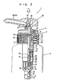
- FIGS. 1 through 5 illustrate the embodiment of the present invention, wherein the numeral 1 designates a liquid jet pump.
- the pump 1 includes a mounting cap 2, a cylinder 3 and a vertically movable member 4.
- the mounting cap 2 serves to fix the cylinders to a container 5 and is constructed such that an inward-flangelike top wall 8 extends from an upper edge of a peripheral wall 7 helically-fitted to an outer periphery of a container cap fitted neck portion 6.
- the cylinder 3 is fixed to the container 5 through the mounting cap 2 and is provided with a suction valve 9 in a lower edge portion vertically formed in the interior of the container.
- a plurality of ribs 10 are protruded in the peripheral direction along an internally lower portion inside the cylinder 3, and stepped engagement recessed portions 11 of the inner side surface and the upper surface opening are respectively formed on both sides of the upper surface of the individual ribs.
- the cylinder 3 has a flange 12 protruding outward from the outer peripheral upper portion, and a fitting cylindrical portion 13 extends downwards from the lower end of the cylinder 3.
- An upper edge of a suction pipe (unillustrated) is fitted to this fitting cylindrical portion 13, and a lower part thereof extends down vertically toward the lower portion of the container.
- the engagement member 14 is constructed such that a fitting cylindrical portion is fitted through a rugged engagement element to the upper edge outer periphery of the cylinder 3 and vertically formed from the top wall lower surface, and an inner cylinder 15 fitted to the inner upper portion of the cylinder from the tip wall inner peripheral edge is also vertically formed.
- the inner cylinder 15 and the upper edge inner surface of the cylinder 3 are hindered from being turning round by vertical protrusions meshing with each other, and, further, a thread for meshing with the vertically movable member is formed along the inner periphery of the inner cylinder 15.
- the pump is constructed in such a way that the outward flange 12 is placed through a packing 16 on the upper surface of the container neck portion 6, and the flange 12 is caught by the top wall 8 of the mounting cap 2 helically fitted to the outer periphery of the container neck portion and by the upper surface of the container neck portion 6.
- the suction valve 9 is constructed such that a ball-like valve member 18 is placed on a valve seat 17 protruding from the inner lower edge of the cylinder 3.
- a cylindrical member 19 is fitted to the inner lower portion of the cylinder 3.
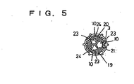
- a flange 21 is peripherally formed along the lower edge of the outer periphery of a cylindrical peripheral wall 20, a top wall 22 horizontally extends at the inner upper portion of the peripheral wall 20, and a window hole 23 is holed in the peripheral wall 22 in the lower portion of the top wall.
- three pieces of radial walls 24 formed at a predetermined intervals and reading to the center extend from the inner surface of the peripheral wall 20 downwardly of the top wall 22, and a notched portion 25 is formed in the lower surface of each radial wall 24. Then, the above flange 21 is fitted to the lower edge'of the engagement recessed portion 11 of each rib 10 formed on the cylinder 3, thus fixing the flange 21 to the cylindrical member 19.
- a lower edge of a coil-like auxiliary spring 26 secured to the upper edge within each notched ortion 25 of the cylindrical member 19 is made to contact and thus engages with the upper surface of the valve member 18 of the suction valve 9, thus biasing the valve 18 in a valve-closing direction at all times.
- This auxiliary spring 26 is formed so that a resiliency of the spring 26 is smaller than the coil spring for biasing a vertically movable member upward, which coil spring will be mentioned later.
- the spring 26 has a strength to such an extent as to make the valve openable by an intra cylinder negative pressure due to a rise of the vertically movable member. Owing to an existence of this auxiliary spring 26, it is possible to prevent a liquid leak caused by to an expansion of the air in the container due to a rise in temperature of the outside air.
- the vertically movable member 4 includes a stem 28 so provided as to be vertically movable within the cylinder 3 in an upwardly biased state with an annular piston 27 installed in the cylinder and protruding from the outer peripheral lower portion.
- the vertically member 4 also includes a push-down head 30 with a nozzle 29 attached to the upper edge of the stem 28, and a discharge valve 31 is provided at the upper portion inside the stem 28.
- the push-down head 30 has a cylindrical casing with an opening formed in the lower edge surface and a peripheral wall perpendicularly extending from the peripheral edge of the top wall, and a lower edge of a vertical cylinder 32 vertically extending from the center of the top wall lower surface of the casing is attached to the outer peripheral upper edge of the stem 28, thus fixing it to the stem 28.
- a horizontal cylinder 33 with its proximal portion opened to the upper front surface of the vertical cylinder 32 penetrates the casing peripheral wall and protrudes forward therefrom, thus forming this horizontal cylinder by way of a nozzle 29.
- the nozzle 29 is constructed so that its proximal portion rises obliquely forward, while its tip is bent obliquely downward.
- a thread formed along the outer periphery of the vertical cylinder 32 with respect to a portion protruding downward from the casing meshes with the thread of the engagement member 14 when pushing down the vertically movable member 4 and is thus made possible of engaging therewith in the state where the vertically movable member 4 is pushed down.
- the construction is such that the inner peripheral lower edge of the stem 28 is liquid-tightly fitted to the outer peripheral upper portion of the cylindrical member peripheral wall 20 on that occasion. Further, the construction is such that the outer peripheral lower edge of the vertical cylinder 32 is liquid-tightly fitted to the inner surface of a reducible diameter portion 34 formed at the lower portion of the inner cylinder 15 of the engagement member 14.
- the discharge valve 31 is provided so that a valve member 35 for clogging the valve hole formed in the inner upper portion of the stem 28 is vertically moved by a liquid pressure.
- valve hole is holed in the center by making a valve seat 36 protrusive at the inner upper portion of the stem 28, the ball-like valve member 35 is put on the valve seat 36, the valve hole is thus clogged, thereby constructing the discharge valve 31.
- the valve member 35 is so constructed as to be vertically movable up to a position where it impinges on the lower surface of an engagement plate 37 extending from the top wall of the casing.
- the vertically movable member 4 is always biased upward by a coil spring 38.
- the coil spring 38 is secured by engaging with the upper surface of the flange having its upper edge fitted and engaged with the lower edge surface of the stem 28 and its lower edge fitted and fixed onto the engagement recessed portion 11, and, as illustrated in FIG. 3, there is formed a liquid passageway 50 which enables the liquid to flow across inwardly outwardly of the lower edge of the spring 38 on both sides thereof.
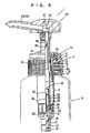
- FIG. 6 illustrates another embodiment of the present invention.
- a protrusion 39 so constructed as to protrude from the inner surface of each rib 10 serves to regulating a rise of the suction valve member 18.
- Other configurations are the same as those in the above-discussed embodiment, and hence the elements are marked with the like numerals.
- each rib 10 is formed as the engagement recessed portion 11 with its inner side surface and its upper surface opening. If there is no cylindrical member 19, however, there may also be a notch groove recessed portion with only upper surface opened. In short, the recessed portion may be formed so that the liquid is allowed to flow across inwardly outwardly of the lower edge of the coil spring 38 on both sides.
- the respective members are properly selectively composed of synthetic resins, metals and materials such as particularly elastomer exhibiting an elasticity.
- the pump according to the present invention is constructed so that the liquid is allowed to flow across inwardly outwardly of the lower edge of the coil spring biasing the vertically movable member at all the times. Therefore, the liquid flowing into the cylinder via the suction valve can be quickly raised up to the upper portion of the cylinder while rising straight especially along the outer portion of the spring. As a result, there is eliminated such an inconvenience that the vertically movable member is decelerated in ascent, and the vertically movable member is capable of moving quickly.
- the vertically movable member is able to perform the smooth movements.
- the pump exhibits such advantages that the pump can be constructed by modifying a part of structure of this kind of conventional pump and is therefore easily manufactured at a low cost.
- the vertically movable member 4 is constructed in the push-down possible-of-engaging manner, and the engagement recessed portion 11 is formed as the engagement recessed portion 11 with the inner side surface and the upper surface opened.
- the flange 21 fitted and fixed to the lower edge portion of each engagement recessed portion 11 is protruded from the outer periphery of the lower edge of the topped peripheral wall 20, a window hole 23 piercing the peripheral wall 20 inside and outside, and, besides, there is provided the cylindrical member 19 constructed so that the outer periphery of the upper edge of the peripheral wall 20 is liquid tightly fittable to the inner surface of the lower edge of the stem in the a push-down possible-of-engaging state.
- the suction valve member 18 is always biased in the valve closing direction by the auxiliary spring 26 interposed between the cylindrical member 19 and the valve member 18 of the suction valve 9, in addition to the effect described above, the suction valve does not open even if the air within the container mounted with the pump expands due to an increase in temperature of the outside air, and accordingly the liquid leakage never happens.
Landscapes
- Closures For Containers (AREA)
- Containers And Packaging Bodies Having A Special Means To Remove Contents (AREA)
- Reciprocating Pumps (AREA)
Abstract
Claims (2)
- Pompe à jet pour liquide, comprenant :dans laquelle,un capuchon de monture (2) adapté à une partie de goulot d'un récipient,un cylindre (3) fixé au récipient à travers le capuchon (2) et comprenant une soupape d'aspiration (9) prévue dans une partie de bord inférieur s'étendant vers le bas à l'intérieur du récipient,une tige (28) comprenant un piston annulaire (27) adapté à l'intérieur du cylindre (3) et faisant saillie par rapport à la partie inférieure de la périphérie extérieure de la tige (28), cette tige (28) étant mobile verticalement,une tête de poussée vers le bas (30) munie d'une buse (29), prévue dans le prolongement du bord supérieur de la tige (28) de manière à être mobile verticalement au-dessus du capuchon de monture (2),une soupape de décharge (31) prévue dans une partie supérieure à l'intérieur de la tige (28), etun ressort hélicoïdal (38) destiné à toujours pousser vers le haut un élément mobile verticalement (4) constitué de la tige et de la tête de poussée vers le bas (30), en étant capable de venir en contact avec la tête (30) par poussée vers le bas, le liquide contenu dans le récipient étant aspiré dans le cylindre (3) par la soupape d'aspiration (9) et le liquide contenu dans le cylindre (3) étant émis sous forme de jet sortant de la buse (29) par l'intermédiaire de la soupape de décharge (31) à partir de la tige, par déplacement de l'élément mobile verticalement (4) vers le haut et vers le bas,
une pluralité de nervures (10) sont disposées dans une partie de bord inférieur à l'intérieur du cylindre (3), en faisant saillie dans la direction radiale et en comprenant, dans leur surface supérieure, une partie en creux d'engagement (11) destinée à recevoir et à fixer le bord inférieur du ressort hélicoïdal (38), tandis que des passages de liquide (50) passant à la fois sur le côté intérieur et sur le côté extérieur du bord inférieur du ressort hélicoïdal (38), sont prévus entre la pluralité de nervures,
la partie d'engagement en creux (11) est formée comme une partie en creux d'engagement (11) dont la surface intérieure et la surface supérieure sont ouvertes, et
une collerette (21) adaptée de façon fixe à la partie de bord inférieur de chacune des parties en creux d'engagement (11), fait saillie par rapport à la périphérie extérieure du bord inférieur d'une paroi périphérique (20) munie d'un dessus, qui est formée dans un élément cylindrique (19) construit de façon que la périphérie extérieure du bord supérieur de la paroi périphérique (20) puisse être adaptée de manière étanche au liquide sur la surface intérieure du bord inférieur de la tige dans un état engagé poussé vers le bas,
caractérisée en ce qu'
un trou de fenêtre (23) communiquant avec l'intérieur et l'extérieur, est formé dans la paroi périphérique (20). - Pompe à jet pour liquide selon la revendication 1,
dans laquelle
un ressort auxiliaire (26) est interposé entre l'élément cylindrique (19) et un élément de soupape (18) de la soupape d'aspiration (9), l'élément de soupape d'aspiration (18) étant ainsi toujours poussé dans une direction de fermeture de la soupape.
Priority Applications (3)
| Application Number | Priority Date | Filing Date | Title |
|---|---|---|---|
| EP01205079A EP1210983B1 (fr) | 1995-01-27 | 1996-01-26 | Pompe à jet pour liquide |
| EP05004286A EP1543886B1 (fr) | 1995-01-27 | 1996-01-26 | Pompe à jet pour liquides comprenant un tige d'ouverture pour la valve de décharge |
| EP05004287A EP1579923B1 (fr) | 1995-01-27 | 1996-01-26 | Poussoir d'une pompe manuelle comportant une tige creuse, un piston et un piston auxiliaire glissant sur la tige |
Applications Claiming Priority (10)
| Application Number | Priority Date | Filing Date | Title |
|---|---|---|---|
| JP3135895 | 1995-01-27 | ||
| JP31358/95 | 1995-01-27 | ||
| JP31359/95 | 1995-01-27 | ||
| JP7031358A JPH08198303A (ja) | 1995-01-27 | 1995-01-27 | 液体噴出ポンプ |
| JP7031359A JPH08198302A (ja) | 1995-01-27 | 1995-01-27 | 液体噴出ポンプ |
| JP3135995 | 1995-01-27 | ||
| JP09810995A JP3569343B2 (ja) | 1995-03-29 | 1995-03-29 | 液体噴出ポンプ |
| JP9810995 | 1995-03-29 | ||
| JP98109/95 | 1995-03-29 | ||
| PCT/JP1996/000156 WO1996022924A1 (fr) | 1995-01-27 | 1996-01-26 | Pompe a jet pour liquide |
Related Child Applications (1)
| Application Number | Title | Priority Date | Filing Date |
|---|---|---|---|
| EP01205079A Division EP1210983B1 (fr) | 1995-01-27 | 1996-01-26 | Pompe à jet pour liquide |
Publications (3)
| Publication Number | Publication Date |
|---|---|
| EP0757004A1 EP0757004A1 (fr) | 1997-02-05 |
| EP0757004A4 EP0757004A4 (fr) | 1999-08-11 |
| EP0757004B1 true EP0757004B1 (fr) | 2004-01-07 |
Family
ID=27287295
Family Applications (4)
| Application Number | Title | Priority Date | Filing Date |
|---|---|---|---|
| EP05004286A Expired - Lifetime EP1543886B1 (fr) | 1995-01-27 | 1996-01-26 | Pompe à jet pour liquides comprenant un tige d'ouverture pour la valve de décharge |
| EP05004287A Expired - Lifetime EP1579923B1 (fr) | 1995-01-27 | 1996-01-26 | Poussoir d'une pompe manuelle comportant une tige creuse, un piston et un piston auxiliaire glissant sur la tige |
| EP01205079A Expired - Lifetime EP1210983B1 (fr) | 1995-01-27 | 1996-01-26 | Pompe à jet pour liquide |
| EP96901130A Expired - Lifetime EP0757004B1 (fr) | 1995-01-27 | 1996-01-26 | Pompe a jet pour liquide |
Family Applications Before (3)
| Application Number | Title | Priority Date | Filing Date |
|---|---|---|---|
| EP05004286A Expired - Lifetime EP1543886B1 (fr) | 1995-01-27 | 1996-01-26 | Pompe à jet pour liquides comprenant un tige d'ouverture pour la valve de décharge |
| EP05004287A Expired - Lifetime EP1579923B1 (fr) | 1995-01-27 | 1996-01-26 | Poussoir d'une pompe manuelle comportant une tige creuse, un piston et un piston auxiliaire glissant sur la tige |
| EP01205079A Expired - Lifetime EP1210983B1 (fr) | 1995-01-27 | 1996-01-26 | Pompe à jet pour liquide |
Country Status (8)
| Country | Link |
|---|---|
| US (5) | US5924604A (fr) |
| EP (4) | EP1543886B1 (fr) |
| KR (1) | KR100311593B1 (fr) |
| CN (4) | CN1098200C (fr) |
| AU (1) | AU717120B2 (fr) |
| CA (5) | CA2440737C (fr) |
| DE (4) | DE69637311T2 (fr) |
| WO (1) | WO1996022924A1 (fr) |
Families Citing this family (59)
| Publication number | Priority date | Publication date | Assignee | Title |
|---|---|---|---|---|
| FR2765638B1 (fr) * | 1997-07-04 | 2004-11-26 | Valois Sa | Pompe manuelle a piston libre a manchette |
| US6209759B1 (en) | 1997-07-04 | 2001-04-03 | Valois S.A. | Hand-operated pump with a free floating sleeve piston |
| CN2314128Y (zh) * | 1997-12-25 | 1999-04-14 | 丁要武 | 乳液泵防进水机构 |
| FR2773355B1 (fr) | 1998-01-08 | 2000-03-17 | Oreal | Dispositif de conditionnement et de distribution comportant un reservoir rempli sous vide et procede de fabrication |
| ES2152814B1 (es) * | 1998-04-30 | 2001-08-16 | Saint Gobain Calmar Sa | Dispensador de fluidos. |
| US6045008A (en) * | 1998-04-30 | 2000-04-04 | Calmar-Monturas, S.A. | Fluid pump dispenser |
| DE69812621T2 (de) * | 1998-09-30 | 2004-02-05 | Novares S.P.A. | In Öffnungs- sowie Schliessstellung abgedichter, handbetätigter Spender |
| FR2791400B1 (fr) * | 1999-03-22 | 2002-04-26 | Sofab | Pompe a reaspiration |
| ID29685A (id) * | 2000-03-15 | 2001-09-20 | Saint Gobain Calmar Sa | Dispenser pompa fluida yang mempunyai ciri penarikan produk |
| CZ298952B6 (cs) * | 2000-03-15 | 2008-03-19 | Saint-Gobain Calmar, S. A. | Cerpací dávkovac |
| US6516976B2 (en) * | 2000-12-19 | 2003-02-11 | Kimberly-Clark Worldwide, Inc. | Dosing pump for liquid dispensers |
| US6543651B2 (en) | 2000-12-19 | 2003-04-08 | Kimberly-Clark Worldwide, Inc. | Self-contained viscous liquid dispenser |
| US6601735B2 (en) | 2001-01-19 | 2003-08-05 | Valois S.A. | Fluid dispenser device |
| US7055721B2 (en) | 2001-03-23 | 2006-06-06 | Chong Woo Co., Ltd. | Finger-operated spray pump ejaculating fluid in fixed quantity |
| EP1249278A1 (fr) * | 2001-04-10 | 2002-10-16 | Taplast S.p.A. | Distributeur à pompe |
| CN1385247A (zh) * | 2001-05-11 | 2002-12-18 | 增田胜利 | 流动体喷出泵 |
| EP1390153A4 (fr) * | 2001-05-30 | 2005-06-15 | Chong Woo Co Ltd | Vaporisateur |
| DE10151781A1 (de) * | 2001-10-19 | 2003-05-08 | Steven Padar | Abgabevorrichtung für Fluide |
| US20040050875A1 (en) * | 2002-02-12 | 2004-03-18 | Yasushi Kobayashi | Liquid dispenser for liquid container |
| US6695171B2 (en) | 2002-02-12 | 2004-02-24 | Seaquistperfect Dispensing Foreign, Inc. | Pump dispenser |
| DE10231751B4 (de) * | 2002-07-13 | 2004-07-29 | Aero Pump GmbH, Zerstäuberpumpen | Saug-Druck-Pumpe zum Ausspritzen eines Produkts aus einem Behältnis |
| KR100995652B1 (ko) | 2003-08-28 | 2010-11-22 | 주식회사 종우실업 | 예압식 저형상 미세 수동 분사펌프 |
| US7389893B2 (en) * | 2003-09-10 | 2008-06-24 | Rieke Corporation | Inverted dispensing pump |
| JP2006027654A (ja) * | 2004-07-15 | 2006-02-02 | Katsutoshi Masuda | 流動体吐出ポンプ |
| US7654418B2 (en) * | 2004-08-30 | 2010-02-02 | Rieke Corporation | Airless dispensing pump |
| US20060113329A1 (en) * | 2004-11-29 | 2006-06-01 | Seaquisperfect Dispensing Foreign, Inc. | Dispenser with lock |
| US7249692B2 (en) | 2004-11-29 | 2007-07-31 | Seaquistperfect Dispensing Foreign, Inc. | Dispenser with lock |
| US7901191B1 (en) | 2005-04-07 | 2011-03-08 | Parker Hannifan Corporation | Enclosure with fluid inducement chamber |
| US7341056B1 (en) * | 2005-05-25 | 2008-03-11 | The Big Ox, L.L.C. | Portable oxygen supply unit |
| CN101224810B (zh) * | 2007-01-19 | 2010-04-14 | 屠旭峰 | 盒式容器 |
| JP2009022935A (ja) * | 2007-07-23 | 2009-02-05 | Canyon Corp | ポンプディスペンサー |
| EP2330049B1 (fr) * | 2008-09-30 | 2017-11-15 | Yoshino Kogyosho Co., Ltd. | Module de tête de pompe foulante pour récipient à refoulement, et pompe foulante comportant un module côté tête et un module côté pompe |
| JP2011055711A (ja) * | 2009-09-07 | 2011-03-24 | Takashi Hida | 動物用自動給水ノズル及び動物用自動給水キャップ体 |
| CN201579158U (zh) * | 2009-12-21 | 2010-09-15 | 陈秋火 | 背吸式防滴漏喷头 |
| US20110303702A1 (en) * | 2010-06-11 | 2011-12-15 | Derxin (Shanghai) Cosmetics Co., Ltd. | Liquid spray head assembly |
| KR101022056B1 (ko) | 2010-07-12 | 2011-03-16 | 양비오 | 개폐 조절이 용이한 펌프식 유체 용기 |
| US20120085789A1 (en) * | 2010-10-07 | 2012-04-12 | Fres-Co System Usa, Inc. | Package system including a fitment with anti-flow blocking and shut-off valve for use with dispensing devices |
| US8960507B2 (en) * | 2011-10-25 | 2015-02-24 | Rieke Corporation | Pump dispenser with an inclined nozzle |
| US9039385B2 (en) | 2011-11-28 | 2015-05-26 | Ford Global Technologies, Llc | Jet pump assembly |
| JP5936991B2 (ja) | 2012-10-31 | 2016-06-22 | 株式会社吉野工業所 | 噴出ヘッド及び、それを備える容器 |
| US9205440B2 (en) * | 2013-10-22 | 2015-12-08 | Yonwoo Co., Ltd. | Dispenser for sucking back contents |
| ITRM20130591A1 (it) * | 2013-10-25 | 2015-04-26 | Emsar Spa | Dispenser a tenuta ermetica |
| WO2015164633A1 (fr) * | 2014-04-23 | 2015-10-29 | Israel Olegnowicz | Verrou intégré pour atomiseur |
| CN104590710B (zh) * | 2015-01-26 | 2017-04-12 | 中山市美捷时包装制品有限公司 | 一种轻量化的乳液泵 |
| CN104969754A (zh) * | 2015-06-30 | 2015-10-14 | 巨野县天胜科技兴农种植专业合作社 | 一种富硒玉米种植器及种植方法 |
| CN106628571B (zh) * | 2015-07-17 | 2018-08-17 | 丁要武 | 乳液泵 |
| WO2017111263A1 (fr) * | 2015-12-24 | 2017-06-29 | 강성일 | Pompe de distribution de contenus |
| US9687866B1 (en) * | 2016-02-19 | 2017-06-27 | Living Fountain Plastic Industrial Co., Ltd. | Liquid soap dispenser |
| JP6930873B2 (ja) | 2017-07-31 | 2021-09-01 | 株式会社吉野工業所 | 吐出ポンプ |
| CN107352153B (zh) * | 2017-08-17 | 2023-10-31 | 重庆尚洁日化用品有限公司 | 一种洗发水瓶 |
| CN107267389B (zh) * | 2017-08-23 | 2020-06-19 | 湖南开启时代生物科技有限责任公司 | 一种细胞扩增装置 |
| CN108516205A (zh) * | 2017-10-10 | 2018-09-11 | 金华知产婺源信息技术有限公司 | 一种无储式按压包装瓶 |
| JP7021913B2 (ja) * | 2017-11-16 | 2022-02-17 | 株式会社ディスコ | 液体供給ユニット |
| CN108945783B (zh) * | 2018-08-01 | 2020-07-28 | 安徽洁诺德塑胶包装有限公司 | 含单向阀的泵头 |
| CR20210506A (es) * | 2019-03-05 | 2022-04-04 | Joseph Company Int Inc | Sistema de recipiente de bebida presurizada |
| CN112320061B (zh) * | 2020-09-24 | 2022-04-08 | 广州市俊杰日化包装容器有限公司 | 一种防滴液按压瓶 |
| CN113117359B (zh) * | 2021-03-05 | 2022-08-26 | 湘雅生物医药(湖州)有限公司 | 一种用于胶原蛋白提取用的无菌式蒸馏瓶 |
| JP2024065852A (ja) * | 2022-10-31 | 2024-05-15 | 株式会社吉野工業所 | 液体噴出器 |
| CN116689178B (zh) * | 2023-05-16 | 2025-10-28 | 中山市联昌喷雾泵有限公司 | 一种按压泵 |
Family Cites Families (55)
| Publication number | Priority date | Publication date | Assignee | Title |
|---|---|---|---|---|
| FR1399208A (fr) * | 1963-06-21 | 1965-05-14 | Lanvin Parfums | Pulvérisateur |
| US3248022A (en) * | 1963-06-21 | 1966-04-26 | Valve Corp Of America | Atomizer pump |
| US3237571A (en) * | 1963-12-16 | 1966-03-01 | Calmar Inc | Dispenser |
| US3228571A (en) | 1964-06-12 | 1966-01-11 | Valve Corp Of America | Discharge valve construction for dispenser pump |
| DE1254970B (de) * | 1965-07-03 | 1967-11-23 | Erich Pfeiffer K G Metallwaren | Abdichtung einer in einem Fluessigkeitsgefaess angeordneten Membranpumpe |
| US3583605A (en) * | 1969-01-17 | 1971-06-08 | Diamond Int Corp | Liquid dispensing pump |
| FR2054453A1 (fr) * | 1969-07-07 | 1971-04-23 | Step Soc Tech Pulverisation | |
| BE752932A (fr) | 1969-07-07 | 1970-12-16 | Pulverisation Par Abreviation | Vaporisateur a tube plongeur |
| FR2149669A5 (fr) * | 1971-08-19 | 1973-03-30 | Step | |
| ES409434A1 (es) * | 1971-12-16 | 1976-01-01 | Pfeiffer Kunststofftech Gmbh | Perfeccionamientos en los dispositivos para emitir liquidoso productos pastosos o cremosos. |
| JPS5186341U (fr) * | 1974-10-23 | 1976-07-10 | ||
| NL173807C (nl) * | 1974-12-18 | 1983-10-03 | Philips Nv | Niet-recursief, digitaal filter met verlaagde uitgangsbemonsterfrequentie. |
| US4057176A (en) * | 1975-07-18 | 1977-11-08 | Plastic Research Products, Inc. | Manually operated spray pump |
| JPS56943Y2 (fr) * | 1976-01-14 | 1981-01-10 | ||
| JPS5295755A (en) * | 1976-02-07 | 1977-08-11 | Yasuo Hirai | Electrostatic painting device |
| US4133457A (en) * | 1976-03-08 | 1979-01-09 | Klassen Edward J | Squeeze bottle with valve septum |
| US4065038A (en) * | 1976-04-07 | 1977-12-27 | Realex Corporation | Pump sprayer |
| US4071172A (en) * | 1976-04-07 | 1978-01-31 | Balogh Stephen M | Manually operated liquid dispenser |
| US4201317A (en) * | 1977-07-28 | 1980-05-06 | Aleff Hans P | Finger actuated pump assembly |
| JPS6040900B2 (ja) * | 1982-01-18 | 1985-09-13 | キヤニヨン株式会社 | デイスペンサ− |
| JPS60140273A (ja) | 1983-12-27 | 1985-07-25 | Sharp Corp | 複写装置における部分消去装置 |
| JPS60140273U (ja) | 1984-02-23 | 1985-09-17 | ソニー株式会社 | テ−プカセツト |
| JPS61140273A (ja) * | 1984-12-12 | 1986-06-27 | Ricoh Co Ltd | 画像拡大・縮小装置 |
| US4624413A (en) * | 1985-01-23 | 1986-11-25 | Corsette Douglas Frank | Trigger type sprayer |
| JPS61140273U (fr) * | 1985-02-20 | 1986-08-30 | ||
| ES288332Y (es) * | 1985-07-24 | 1986-08-01 | Monturas Y Fornituras,S.A. | Bomba surtidora de fluido contenido en un recipiente. |
| JPH0423815Y2 (fr) * | 1986-02-04 | 1992-06-03 | ||
| JPH0547099Y2 (fr) * | 1987-06-26 | 1993-12-10 | ||
| JPS6479760A (en) * | 1987-09-21 | 1989-03-24 | Canon Kk | Image recorder |
| JPH0444791Y2 (fr) | 1987-11-19 | 1992-10-21 | ||
| JPH0698987B2 (ja) * | 1988-02-02 | 1994-12-07 | 株式会社多田技術研究所 | ディスペンサ |
| JPH076110Y2 (ja) * | 1988-06-03 | 1995-02-15 | 株式会社吉野工業所 | 液体吐出容器 |
| JP2638110B2 (ja) * | 1988-08-26 | 1997-08-06 | トヨタ自動車株式会社 | ダイカスト鋳造における金型温度制御方法 |
| US4991747A (en) * | 1988-10-11 | 1991-02-12 | Risdon Corporation | Sealing pump |
| JPH0259164U (fr) * | 1988-10-25 | 1990-04-27 | ||
| US4930670A (en) * | 1989-03-17 | 1990-06-05 | Smiley Chien | Pumping mechanism for dispensing lotion in bottle/container |
| IT1228787B (it) * | 1989-03-31 | 1991-07-03 | Lumson Srl | Pompetta manuale per l'erogazione di liquidi o paste da flaconi. |
| JPH0329466A (ja) * | 1989-06-26 | 1991-02-07 | Nec Corp | ファクシミリ装置 |
| US4991746A (en) * | 1989-07-07 | 1991-02-12 | Emson Research Inc. | Modular pump having a locking rotatable sleeve |
| JPH0329466U (fr) * | 1989-07-31 | 1991-03-25 | ||
| FR2656900B1 (fr) * | 1990-01-10 | 1994-01-28 | Oreal | Pompe manuelle a precompression pour la pulverisation d'un liquide, notamment d'un parfum. |
| US5346103A (en) * | 1990-10-05 | 1994-09-13 | Yoshino Kogyosho Co, Ltd. | Compression sprayer for liquids |
| FR2668958B1 (fr) * | 1990-11-13 | 1994-05-20 | Valois | Dispositif de pulverisation ou de distribution de produit fluide, a aspiration du produit contenu dans le canal de sortie en fin d'actionnement. |
| FR2669379A1 (fr) * | 1990-11-21 | 1992-05-22 | Promotion Rech Innovation Tec | Pompe doseuse pour produits liquides. |
| US5192006A (en) * | 1991-05-01 | 1993-03-09 | Risdon Corporation | Low profile pump |
| US5152435A (en) * | 1991-06-13 | 1992-10-06 | Ben Zane Cohen | Ophthalmic dispensing pump |
| WO1993025319A1 (fr) * | 1992-06-17 | 1993-12-23 | Yoshino Kogyosho Co., Ltd. | Buse de sortie pour pompe |
| JP3163776B2 (ja) * | 1992-08-25 | 2001-05-08 | 東洋製罐株式会社 | ポンプ |
| KR960703353A (ko) * | 1993-06-24 | 1996-08-17 | 자코부스 코르넬리즈 래서 | 일체식 수송용 밀봉부를 갖는 절첩식 펌프실을 구비한 펌프장치(Pump device with collapsible pump chamber having integral shipping seal) |
| US5988443A (en) * | 1994-04-15 | 1999-11-23 | Owens-Brockway Plastic Products Inc. | Flexible tube with pump dispenser and method of making |
| US5549223A (en) * | 1994-08-03 | 1996-08-27 | Toyo Seikan Kaisha, Ltd. | Pump with back suction phase |
| US5673824A (en) * | 1995-05-31 | 1997-10-07 | Taplast Srl | Plastic dosing pump for dispensing liquids from containers |
| JP3595016B2 (ja) * | 1995-04-04 | 2004-12-02 | 株式会社吉野工業所 | 液体噴出容器 |
| US6053371A (en) * | 1998-05-15 | 2000-04-25 | Owens-Illinois Closure Inc. | Pump dispenser and method for making same |
| US6186368B1 (en) * | 1999-05-26 | 2001-02-13 | Michael Gene Knickerbocker | Manually actuated pump assembly |
-
1996
- 1996-01-26 CN CN96190063A patent/CN1098200C/zh not_active Expired - Lifetime
- 1996-01-26 AU AU44965/96A patent/AU717120B2/en not_active Expired
- 1996-01-26 DE DE69637311T patent/DE69637311T2/de not_active Expired - Lifetime
- 1996-01-26 EP EP05004286A patent/EP1543886B1/fr not_active Expired - Lifetime
- 1996-01-26 DE DE69638012T patent/DE69638012D1/de not_active Expired - Lifetime
- 1996-01-26 CN CNB021199353A patent/CN100402157C/zh not_active Expired - Lifetime
- 1996-01-26 DE DE69631269T patent/DE69631269T2/de not_active Expired - Lifetime
- 1996-01-26 KR KR1019960705313A patent/KR100311593B1/ko not_active Expired - Lifetime
- 1996-01-26 CN CNB2005100517860A patent/CN100375657C/zh not_active Expired - Lifetime
- 1996-01-26 CA CA2440737A patent/CA2440737C/fr not_active Expired - Lifetime
- 1996-01-26 CA CA2485237A patent/CA2485237C/fr not_active Expired - Lifetime
- 1996-01-26 CA CA2665953A patent/CA2665953C/fr not_active Expired - Lifetime
- 1996-01-26 EP EP05004287A patent/EP1579923B1/fr not_active Expired - Lifetime
- 1996-01-26 EP EP01205079A patent/EP1210983B1/fr not_active Expired - Lifetime
- 1996-01-26 EP EP96901130A patent/EP0757004B1/fr not_active Expired - Lifetime
- 1996-01-26 DE DE69635938T patent/DE69635938T2/de not_active Expired - Lifetime
- 1996-01-26 CA CA002426367A patent/CA2426367C/fr not_active Expired - Lifetime
- 1996-01-26 US US08/716,174 patent/US5924604A/en not_active Expired - Lifetime
- 1996-01-26 CA CA002186614A patent/CA2186614C/fr not_active Expired - Lifetime
- 1996-01-26 WO PCT/JP1996/000156 patent/WO1996022924A1/fr not_active Ceased
-
1999
- 1999-01-08 US US09/227,137 patent/US6119902A/en not_active Expired - Lifetime
-
2001
- 2001-12-27 US US10/026,907 patent/US6702156B2/en not_active Expired - Fee Related
-
2002
- 2002-05-15 CN CNB021199345A patent/CN1232356C/zh not_active Expired - Lifetime
-
2004
- 2004-01-15 US US10/757,396 patent/US6938803B2/en not_active Expired - Fee Related
-
2005
- 2005-03-30 US US11/093,224 patent/US7472809B2/en not_active Expired - Fee Related
Also Published As
Similar Documents
| Publication | Publication Date | Title |
|---|---|---|
| EP1210983B1 (fr) | Pompe à jet pour liquide | |
| US5186368A (en) | Shutter for the outlet channel of a dispenser head for semi-liquid substances, and a dispenser head advantageously associated therewith | |
| AU767639B2 (en) | High volume aerosol valve | |
| US6382463B2 (en) | Spray dispensing device with nozzle closure | |
| KR100981690B1 (ko) | 수동 펌프 분배기 | |
| KR20030069997A (ko) | 에어로졸 스프레이 분배기 | |
| US4212332A (en) | Manually operated pump for dispensing product from a container | |
| US11738360B2 (en) | Spray cap for spray container | |
| EP1242148B1 (fr) | Tete de distribution pour distributeur pressable | |
| CN100354046C (zh) | 带有分配头的流体产品分配装置 | |
| AU2001245655A1 (en) | Method of using a dispensing head for a squeeze dispenser | |
| AU738185B2 (en) | Liquid jet pump | |
| JPH10179239A (ja) | 内容物噴出容器と該噴出容器を用いた器具 | |
| CA1126702A (fr) | Bombe aerosol | |
| GB2432406A (en) | Aerosol valve |
Legal Events
| Date | Code | Title | Description |
|---|---|---|---|
| PUAI | Public reference made under article 153(3) epc to a published international application that has entered the european phase |
Free format text: ORIGINAL CODE: 0009012 |
|
| 17P | Request for examination filed |
Effective date: 19960927 |
|
| AK | Designated contracting states |
Kind code of ref document: A1 Designated state(s): CH DE FR GB IT LI NL |
|
| A4 | Supplementary search report drawn up and despatched |
Effective date: 19990628 |
|
| AK | Designated contracting states |
Kind code of ref document: A4 Designated state(s): CH DE FR GB IT LI NL |
|
| 17Q | First examination report despatched |
Effective date: 20010817 |
|
| GRAH | Despatch of communication of intention to grant a patent |
Free format text: ORIGINAL CODE: EPIDOS IGRA |
|
| GRAS | Grant fee paid |
Free format text: ORIGINAL CODE: EPIDOSNIGR3 |
|
| GRAA | (expected) grant |
Free format text: ORIGINAL CODE: 0009210 |
|
| AK | Designated contracting states |
Kind code of ref document: B1 Designated state(s): CH DE FR GB IT LI NL |
|
| REG | Reference to a national code |
Ref country code: GB Ref legal event code: FG4D |
|
| REG | Reference to a national code |
Ref country code: CH Ref legal event code: EP |
|
| REG | Reference to a national code |
Ref country code: CH Ref legal event code: NV Representative=s name: KELLER & PARTNER PATENTANWAELTE AG |
|
| REF | Corresponds to: |
Ref document number: 69631269 Country of ref document: DE Date of ref document: 20040212 Kind code of ref document: P |
|
| ET | Fr: translation filed | ||
| PLBE | No opposition filed within time limit |
Free format text: ORIGINAL CODE: 0009261 |
|
| STAA | Information on the status of an ep patent application or granted ep patent |
Free format text: STATUS: NO OPPOSITION FILED WITHIN TIME LIMIT |
|
| 26N | No opposition filed |
Effective date: 20041008 |
|
| PGFP | Annual fee paid to national office [announced via postgrant information from national office to epo] |
Ref country code: CH Payment date: 20050124 Year of fee payment: 10 |
|
| PGFP | Annual fee paid to national office [announced via postgrant information from national office to epo] |
Ref country code: NL Payment date: 20050126 Year of fee payment: 10 |
|
| PG25 | Lapsed in a contracting state [announced via postgrant information from national office to epo] |
Ref country code: LI Free format text: LAPSE BECAUSE OF NON-PAYMENT OF DUE FEES Effective date: 20060131 Ref country code: CH Free format text: LAPSE BECAUSE OF NON-PAYMENT OF DUE FEES Effective date: 20060131 |
|
| PGFP | Annual fee paid to national office [announced via postgrant information from national office to epo] |
Ref country code: IT Payment date: 20060131 Year of fee payment: 11 |
|
| PG25 | Lapsed in a contracting state [announced via postgrant information from national office to epo] |
Ref country code: NL Free format text: LAPSE BECAUSE OF NON-PAYMENT OF DUE FEES Effective date: 20060801 |
|
| REG | Reference to a national code |
Ref country code: CH Ref legal event code: PL |
|
| NLV4 | Nl: lapsed or anulled due to non-payment of the annual fee |
Effective date: 20060801 |
|
| PG25 | Lapsed in a contracting state [announced via postgrant information from national office to epo] |
Ref country code: IT Free format text: LAPSE BECAUSE OF NON-PAYMENT OF DUE FEES Effective date: 20070126 |
|
| REG | Reference to a national code |
Ref country code: FR Ref legal event code: PLFP Year of fee payment: 20 |
|
| PGFP | Annual fee paid to national office [announced via postgrant information from national office to epo] |
Ref country code: DE Payment date: 20150120 Year of fee payment: 20 |
|
| PGFP | Annual fee paid to national office [announced via postgrant information from national office to epo] |
Ref country code: GB Payment date: 20150121 Year of fee payment: 20 Ref country code: FR Payment date: 20150108 Year of fee payment: 20 |
|
| REG | Reference to a national code |
Ref country code: DE Ref legal event code: R071 Ref document number: 69631269 Country of ref document: DE |
|
| REG | Reference to a national code |
Ref country code: GB Ref legal event code: PE20 Expiry date: 20160125 |
|
| PG25 | Lapsed in a contracting state [announced via postgrant information from national office to epo] |
Ref country code: GB Free format text: LAPSE BECAUSE OF EXPIRATION OF PROTECTION Effective date: 20160125 |