EP0757150A2 - Rahmen für Fenster, Türen, Fassaden oder dergleichen - Google Patents
Rahmen für Fenster, Türen, Fassaden oder dergleichen Download PDFInfo
- Publication number
- EP0757150A2 EP0757150A2 EP96107533A EP96107533A EP0757150A2 EP 0757150 A2 EP0757150 A2 EP 0757150A2 EP 96107533 A EP96107533 A EP 96107533A EP 96107533 A EP96107533 A EP 96107533A EP 0757150 A2 EP0757150 A2 EP 0757150A2
- Authority
- EP
- European Patent Office
- Prior art keywords
- container
- adhesive
- connecting element
- shells
- hollow profiles
- Prior art date
- Legal status (The legal status is an assumption and is not a legal conclusion. Google has not performed a legal analysis and makes no representation as to the accuracy of the status listed.)
- Granted
Links
- 239000000853 adhesive Substances 0.000 claims abstract description 38
- 230000001070 adhesive effect Effects 0.000 claims abstract description 38
- 238000001125 extrusion Methods 0.000 claims abstract description 11
- 229910052751 metal Inorganic materials 0.000 claims abstract description 4
- 239000002184 metal Substances 0.000 claims abstract description 4
- 239000011888 foil Substances 0.000 claims description 6
- 238000003780 insertion Methods 0.000 claims description 4
- 230000037431 insertion Effects 0.000 claims description 4
- 229910052782 aluminium Inorganic materials 0.000 claims description 3
- XAGFODPZIPBFFR-UHFFFAOYSA-N aluminium Chemical compound [Al] XAGFODPZIPBFFR-UHFFFAOYSA-N 0.000 claims description 3
- 240000005702 Galium aparine Species 0.000 description 2
- 239000003292 glue Substances 0.000 description 1
Images

Classifications
-
- E—FIXED CONSTRUCTIONS
- E06—DOORS, WINDOWS, SHUTTERS, OR ROLLER BLINDS IN GENERAL; LADDERS
- E06B—FIXED OR MOVABLE CLOSURES FOR OPENINGS IN BUILDINGS, VEHICLES, FENCES OR LIKE ENCLOSURES IN GENERAL, e.g. DOORS, WINDOWS, BLINDS, GATES
- E06B3/00—Window sashes, door leaves, or like elements for closing wall or like openings; Layout of fixed or moving closures, e.g. windows in wall or like openings; Features of rigidly-mounted outer frames relating to the mounting of wing frames
- E06B3/96—Corner joints or edge joints for windows, doors, or the like frames or wings
- E06B3/964—Corner joints or edge joints for windows, doors, or the like frames or wings using separate connection pieces, e.g. T-connection pieces
- E06B3/968—Corner joints or edge joints for windows, doors, or the like frames or wings using separate connection pieces, e.g. T-connection pieces characterised by the way the connecting pieces are fixed in or on the frame members
- E06B3/9681—Corner joints or edge joints for windows, doors, or the like frames or wings using separate connection pieces, e.g. T-connection pieces characterised by the way the connecting pieces are fixed in or on the frame members by press fit or adhesion
- E06B3/9682—Mitre joints
Definitions
- the invention relates to a frame for windows, doors, facades or the like, preferably made of metal, interconnected hollow profiles, also in the form of tubes, with a connecting element which engages in the hollow profiles, in particular a corner connector, which is attached to one or more of the connecting hollow profiles on the inner circumferential surface adjacent connecting surfaces has an area provided with adhesive, a receiving pocket for the adhesive being provided in each case on the connecting surface (s) to be bonded, in which the adhesive is arranged in a receptacle during assembly of the connecting element, further on the connecting element a connecting groove for attaching the container or a carrier part holding the container is provided.
- Such frames are known for example from DE 195 02 817.
- the invention is based on the object of providing suitable means in a frame of the type mentioned at the outset, which enables the adhesive to be used in the individual case to be attached to the connecting element in an easy and quick, yet reliable manner.
- the container is designed as a deep-drawn container which has one or more shells for the adhesive and an extrusion part is provided which covers the shells, is adjustable against them and thereby in its outer Dimensions correspond approximately to the receiving pocket, with connection means being arranged on the deep-drawing container and on the extrusion part in each case on the edge, which engage in a form-fitting manner in the connection groove.
- the advantage achieved by the invention consists essentially in the fact that the use of a deep-drawing container makes it easy to handle and attach the adhesive to the connecting element.
- a deep-drawing container makes it easy to handle and attach the adhesive to the connecting element.
- suitably arranged trays can be provided in the deep-drawing container, which can be designed or aligned in accordance with the adhesive to be used. Regardless of this, the extrusion ensures that the shells when inserting the Connecting element in the hollow profiles are largely completely emptied, so that practically the entire amount of the adhesive provided for the adhesive is used.
- the pressed-out part is provided with projections adapted to the shape of the shells, since the webs of the deep-drawn container formed between the shells then do not have to be deformed when the adhesive is pressed out.
- connection means on the deep-drawing container is expediently formed by a fastening tab, the free end of which is rounded in the form of a sleeve, the connection means on the extrusion part expediently having a web, at the end of which a connecting rib enclosed by the sleeve-shaped end of the fastening tab is arranged.
- thermoformed container is expediently designed such that a separate shell is provided for each component of a multi-component adhesive.
- the shells can be covered by a foil, preferably an aluminum foil.
- the shells are provided with predetermined breaking points, which are preferably directed towards one another.
- the object on which this is based is achieved in that the receiving pocket is snapped onto the one to be snapped into the connecting groove Carrier part is arranged, the carrier part carrying two lamellae arranged on a central web and spreading in an arrow shape in the direction of insertion of the connecting element, between which the container is arranged.
- the container expediently again has two chambers which hold the two components of a two-component adhesive and which are separated from one another along the central web of the carrier part.
- the connecting groove is in this case expediently arranged on the end face of the connecting element, since as a result the carrier part cannot come loose automatically when the connecting element is inserted into the hollow profile.
- the carrier part can be provided with a support strip which bears against the connecting element.
- a connecting element 2 designed as a corner connector is shown, which is used in frames for windows, doors, facades and the like. These are constructed from interconnected hollow profiles cut at miter corners. These hollow profiles are not shown in the drawing.
- the connecting element 2 is provided with an adhesive 4 on one or more of its connecting surfaces which abut the inner lateral surface of the hollow profiles to be connected.
- the adhesive 4 is first arranged in a receiving pocket 5 before the connection element 2 is assembled, the adhesive 4 being accommodated in a container 6.
- One or more connecting grooves 7 are provided on the connecting element itself, which are provided for attaching the container 6 or else a carrier part 8 holding the container 6.
- the container 6 is designed as a deep-drawing container which has two shells 6.1 for the adhesive 4. Furthermore, an extrusion 9 is provided which covers the shells 6.1 and is adjustable against them. The outer part of the pressed-out part 9 corresponds approximately to the receiving pocket 5.
- connection means 10 are arranged at the edges, which engage in the connection groove 7 in a form-fitting manner. This ensures that the deep-drawn container and the extrusion 9 are held securely on the connecting element 2, that is to say they cannot accidentally fall off before assembly.
- the extrusion 9 can also be provided with projections adapted to the shape of the trays, so that the trays 6.1 can be emptied without the between they have to deform web 11 formed.
- the connecting means 10 on the deep-drawing container 6 is formed by a fastening tab, the free end 12 of which is rounded in the form of a sleeve.
- the connecting means 10 on the extrusion part 9 has a web, at the end of which a connecting rib 13, which is surrounded by the sleeve-shaped end 12 of the fastening tab, is arranged. This design can be seen in particular in FIG. 1, on the leg of the connecting element 2 pointing vertically upward.
- the deep-drawing container 6, as can be seen in particular from FIG. 4, has two shells 6.1.
- the shells 6.1 themselves are covered with a foil 14, preferably an aluminum foil.
- the shells are provided with predetermined breaking points facing one another, so that it is ensured that the shells 6.1 do not burst open at areas which are facing away from one another, which would lead to inadequate mixing of the two components of the adhesive 4 .
- the receiving pocket 5 is arranged on the carrier part 8 to be locked in the connecting groove 7, the carrier part 8 having a central web 16 on which two lamellae 17 which are spread out in the shape of an arrow in the insertion direction of the connecting element are arranged .
- the container 6 with the adhesive 4 has a wedge-shaped here Shape so that it can be placed between the fins 17.
- the thickness of the slats 17 and the central web 16 are dimensioned such that after the insertion of the carrier part 8 into the hollow profile, the slats 17 almost rest against the central web 16.
- the container 6 is in turn designed such that it has two chambers which hold the two components of a two-component adhesive. These chambers are separated from one another along the central web of the carrier part, as can be seen in particular from the end view in FIG. 9.
- the connecting groove 7, as can be seen from FIG. 7, is arranged on the end face of the connecting element 2, as a result of which the carrier part 8 cannot become detached from the connecting element 2 when it is inserted into the hollow profile.
- the carrier part 8 is provided with a support strip 18 which bears against the connecting element 2.
Landscapes
- Engineering & Computer Science (AREA)
- Civil Engineering (AREA)
- Structural Engineering (AREA)
- Wing Frames And Configurations (AREA)
- Packages (AREA)
- Special Wing (AREA)
- Rigid Containers With Two Or More Constituent Elements (AREA)
- Joining Of Corner Units Of Frames Or Wings (AREA)
- Securing Of Glass Panes Or The Like (AREA)
Abstract
Description
- Die Erfindung betrift einen Rahmen für Fenster, Türen, Fassaden oder dergleichen, aus vorzugsweise aus Metall bestehenden, miteinander verbundenen Hohlprofilen, auch in Form von Rohren, mit einem in die Hohlprofile greifenden Verbindungselement, insbesondere einem Eckverbinder, das an einer oder mehreren seiner den zu verbindenden Hohlprofilen an deren Innenmantelfläche anliegenden Verbindungsflächen einen mit Kleber versehenen Bereich aufweist, wobei an der/den zu verklebenden Verbindungsflächen jeweils eine Aufnahmetasche für den Kleber vorgesehen ist, in der der Kleber bei der Montage des Verbindungselements in einem Behältnis angeordnet ist, wobei weiter am Verbindungselement eine Anschlußnut zum Anbringen des Behältnisses oder eines das Behältnis haltenden Trägerteils vorgesehen ist.
- Derartige Rahmen sind beispielsweise aus der DE 195 02 817 bekannt. Je nach Anwendungsfall ist es erforderlich, geeignet abgepackte Kleber zum Einsatz bringen zu können, wobei gleichzeitig sicher gestellt sein muß, daß der Kleber beim Montieren der Verbindungselemente weitgehend vollständig aus dem Behältnis ausgepreßt wird.
- Der Erfindung liegt die Aufgabe zugrunde, bei einem Rahmen der eingangs genannten Art geeignete Mittel vorzusehen, die eine leichte und schnelle, dabei zugleich zuverlässig haltende Anbringung des jeweils im Einzelfall zu verwendenden Klebers an dem Verbindungselement ermöglicht.
- Nach einer ersten Ausführungsform der Erfindung wird diese Aufgabe dadurch gelöst, daß das Behältnis als Tiefziehbehälter ausgebildet ist, der eine oder mehrere Schalen für den Kleber aufweist und ein Auspreßteil vorgesehen ist, das die Schalen überdeckt, gegen diese hin verstellbar ist und dabei in seinen äußeren Abmessungen etwa der Aufnahmetasche entspricht, wobei am Tiefziehbehälter und am Auspreßteil jeweils randseitig Anschlußmittel angeordnet sind, die formschlüssig in die Anschlußnut greifen.
- Der durch die Erfindung erreichte Vorteil besteht im wesentlichen darin, daß durch die Verwendung eines Tiefziehbehälters eine einfache Handhabung und Anbringung des Klebers an dem Verbindungselement erreicht wird. Hierdurch lassen insbesondere geeignet angeordnete Schalen im Tiefziehbehälter vorsehen, die entsprechend dem zur Anwendung kommenden Kleber ausgebildet bzw. ausgerichtet sein können. Unabhängig hiervon gewährleistet das Auspreßteil, daß die Schalen beim Einschieben des Verbindungselements in die Hohlprofile weitgehend vollständig entleert werden, so daß praktisch die gesamte Menge des für die Verklebung vorgesehenen Klebers zur Anwendung kommt.
- Vorteilhaft im Rahmen der Erfindung ist es hierbei, wenn das Auspreßteil mit der Form der Schalen angepaßten Vorsprüngen versehen ist, da dann beim Auspressen des Klebers die zwischen den Schalen gebildeten Stege des Tiefziehbehälters nicht verformt werden müssen.
- Das Anschlußmittel am Tiefziehbehälter ist zweckmäßigerweise von einer Befestigungslasche gebildet, dessen freies Ende hülsenförmig verrundet ausgebildet ist, wobei weiter das Anschlußmittel am Auspreßteil zweckmäßigerweise einen Steg aufweist, an dessen Ende eine von dem hülsenförmigen Ende der Befestigungslasche umschlossene Anschlußrippe angeordnet ist.
- Weiter ist der Tiefziehbehälter zweckmäßigeweise so ausgebildet, daß für jeden Bestandteil eines Mehr-Komponenten-Klebers eine eigene Schale vorgesehen ist. Die Schalen können dabei von einer Folie, vorzugsweise einer Aluminiumfolie, abgedeckt sein.
- Um eine gute Durchmischung der in den Schalen getrennt untergebrachten Komponenten des Klebers zu erreichen, sind die Schalen mit vorzugsweise zueinander gerichteten Sollbruchstellen versehen.
- Nach einer zweiten Ausführungsform der Erfindung wird die hier zugrunde liegende Aufgabe dadurch gelöst, daß die Aufnahmetasche an dem in der Anschlußnut einzurastenden Trägerteil angeordnet ist, wobei das Trägerteil zwei an einem Mittelsteg angeordnete, in Einschubrichtung des Verbindungselements pfeilförmig aufgespreizte Lamellen trägt, zwischen denen das Behältnis angeordnet ist.
- Bei dieser Ausführungsform besteht der Vorteil, daß das gesamte Trägerteil fertig konfektioniert sein kann, so daß es lediglich in die Anschlußnut eingerastet bzw. eingeschnappt werden muß.
- Das Behältnis weist hierbei zweckmäßigerweise wieder zwei die beiden Bestandteile eines Zwei-Komponenten-Klebers aufnehmende Kammern auf, die längs des Mittelsteges des Trägerteils voneinander getrennt sind. Beim Einschieben des Verbindungselements in das Hohlprofil werden dabei die aufgespreizten Lamellen zusammengedrückt, wodurch die Kammern aufplatzen und die Bestandteile miteinander vermischt werden.
- Die Anschlußnut ist hierbei zweckmäßigerweise stirnseitig am Verbindungselement angeordnet, da sich hierdurch das Trägerteil beim Einschieben des Verbindungselements in das Hohlprofil nicht selbsttätig lösen kann.
- Zusätzlich kann das Trägerteil mit einer dem Verbindungselement anliegenden Stützleiste versehen sein.
- Im folgenden wird die Erfindung an in der Zeichnung dargestellten Ausführungsbeispielen näher erläutert; es zeigen:
- Fig. 1
- das als Eckverbinder ausgebildete Verbindungselement eines aus Hohlprofilen bestehenden Rahmens,
- Fig. 2
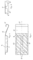
- das als Tiefziehbehälter ausgebildete Behältnis für den Kleber,
- Fig. 3
- das zugehörige Auspreßteil,
- Fig. 4
- den Gegenstand nach Fig. 2 in Draufsicht,
- Fig. 5
- eine detailiertere Darstellung des Gegenstands nach Fig. 2,
- Fig. 6
- die Stirnansicht des Gegenstands nach Fig. 5,
- Fig. 7
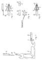
- eine der Fig. 1 entsprechende Darstellung eines zweiten Ausführungsbeispiels,
- Fig. 8
- das Trägerteil aus Fig. 7,
- Fig. 9
- ein Behältnis mit Kleber für das Trägerteil,
- Fig. 10
- das Trägerteil mit dem Kleberbehältnis.
- In den Fig. 1 und 7 ist ein als Eckverbinder ausgebildetes Verbindungselement 2 dargestellt, das bei Rahmen für Fenster, Türen, Fassaden und dergl. zum Einsatz kommt, die aus miteinander verbundenen, bei Eckverbindungen auf Gehrung geschnittenen Hohlprofilen aufgebaut sind. Diese Hohlprofile sind in der Zeichnung nicht dargestellt.
- Um eine stabile Verbindung zwischen den Hohlprofilen und dem Verbindungselement 2 zu gewährleisten, ist das Verbindungselement 2 an einer oder mehreren seiner Verbindungsflächen, die der Innenmantelfläche der zu verbindenden Hohlprofile anliegen, mit einem Kleber 4 versehen. Der Kleber 4 wird dazu vor der Montage des Verbindungselementes 2 zunächst in einer Aufnahmetasche 5 angeordnet, wobei der Kleber 4 in einem Behältnis 6 untergebracht ist.
- Am Verbindungselement selbst sind eine oder mehrere Anschlußnuten 7 vorgesehen, die zum Anbringen des Behältnisses 6 oder aber eines das Behältnis 6 haltenden Trägerteils 8 vorgesehen sind.
- In dem Ausführungsbeispiel nach den Fig. 1 bis 6 ist das Behältnis 6 als Tiefziehbehälter ausgebildet, der zwei Schalen 6.1 für den Kleber 4 aufweist. Ferner ist ein Auspreßteil 9 vorgesehen, das die Schalen 6.1 überdeckt und gegen diese hin verstellbar ist. Dabei entspricht das Auspreßteil 9 in seinen äußeren Abmessungen etwa der Aufnahmetasche 5.
- Am Tiefziehbehälter und am Auspreßteil 9 sind jeweils randseitig Anschlußmittel 10 angeordnet, die formschlüssig in die Anschlußnut 7 greifen. Hierdurch ist sicher gestellt, daß der Tiefziehbehälter und das Auspreßteil 9 sicher am Verbindungselement 2 gehalten sind, also nicht versehentlich vor der Montage abfallen können.
- Das Auspreßteil 9 kann hierbei auch mit der Form der Schalen angepaßten Vorsprüngen versehen sein, so daß das Entleeren der Schalen 6.1 möglich ist, ohne den zwischen ihnen gebildeten Steg 11 verformen zu müssen.
- Das Anschlußmittel 10 am Tiefziehbehälter 6 ist von einer Befestigungslasche gebildet, deren freies Ende 12 hülsenförmig verrundet ausgebildet ist. Das Anschlußmittel 10 am Auspreßteil 9 weist einen Steg auf, an dessen Ende eine von dem hülsenförmigen Ende 12 der Befestigungslasche umschlossene Anschlußrippe 13 angeordnet ist. Diese Ausbildung ist insbesondere in Fig. 1, an dem senkrecht nach oben weisenden Schenkel des Verbindungselements 2 zu sehen.
- In der Regel werden für die Verklebung Zwei-Komponenten-Kleber eingesetzt. Hierfür weist der Tiefziehbehälter 6, wie insbesondere aus Fig. 4 zu ersehen, zwei Schalen 6.1 auf. Die Schalen 6.1 selbst sind mit einer Folie 14, vorzugsweise einer Aluminiumfolie, abgedeckt.
- Wie in Fig. 4 mit der Bezugsziffer 15 angedeutet, sind die Schalen mit zueinander gerichteten Sollbruchstellen versehen, so daß sicher gestellt ist, daß die Schalen 6.1 nicht an einander abgewandten Bereichen aufplatzen, was zu einer ungenügenden Durchmischung der beiden Komponenten des Klebers 4 führen würde.
- Bei einer zweiten, in den Fig. 7 bis 10 dargestellten Ausführungsform ist die Aufnahmetasche 5 an dem in der Anschlußnut 7 einzurastenden Trägerteil 8 angeordnet, wobei das Trägerteil 8 einen Mittelsteg 16 aufweist, an dem zwei in Einschubrichtung des Verbindungselements pfeilförmig aufgespreizte Lamellen 17 angeordnet sind. Das Behältnis 6 mit dem Kleber 4 besitzt hier eine keilförmige Gestalt, so daß es zwischen den Lamellen 17 angeordnet werden kann. Die Dicke der Lamellen 17 und des Mittelstegs 16 sind dabei so bemessen, daß nach dem Einschieben des Trägersteils 8 in das Hohlprofil die Lamellen 17 dem Mittelsteg 16 nahezu anliegen.
- Das Behältnis 6 ist wiederum so ausgebildet, daß es zwei die beiden Bestandteile eines Zwei-Komponenten-Klebers aufnehmende Kammern aufweist. Diese Kammern sind längs des Mittelsteges des Trägerteils voneinander getrennt, wie insbesondere aus der Stirnansicht in Fig. 9 zu ersehen ist.
- Die Anschlußnut 7 ist, wie sich aus der Fig. 7 ersehen läßt, stirnseitig am Verbindungselement 2 angeordnet, wodurch sich das Trägerteil 8 beim Einschieben in das Hohlprofil nicht vom Verbindungselement 2 lösen kann. Zur Erhöhung der Stabilität ist das Trägerteil 8 mit einer dem Verbindungselement 2 anliegenden Stützleiste 18 versehen.
Claims (10)
- Rahmen für Fenster, Türen, Fassaden oder dergleichen, aus vorzugsweise aus Metall bestehenden, miteinander verbundenen Hohlprofilen, auch in Form von Rohren, mit einem in die Hohlprofile greifenden Verbindungselement (2), insbesondere einem Eckverbinder, das an einer oder mehreren seiner den zu verbindenden Hohlprofilen an deren Innenmantelfläche anliegenden Verbindungsflächen einen mit Kleber (4) versehenen Bereich aufweist, wobei an der/den zu verklebenden Verbindungsflächen jeweils eine Aufnahmetasche (5) für den Kleber (4) vorgesehen ist, in der der Kleber (4) bei der Montage des Verbindungselements (2) in einem Behältnis (6) angeordnet ist, wobei weiter am Verbindungselement (2) eine Anschlußnut (7) zum Anbringen des Behältnisses (6) oder eines das Behältnis (6) haltenden Trägerteils (8) vorgesehen ist, dadurch gekennzeichnet, daß das Behältnis (6) als Tiefziehbehälter ausgebildet ist, der eine oder mehrere Schalen (6.1) für den Kleber (4) aufweist und ein Auspreßteil (9) vorgesehen ist, das die Schalen (6.1) überdeckt, gegen diese hin verstellbar ist und dabei in seinen äußeren Abmessungen etwa der Aufnahmetasche (5) entspricht, wobei am Tiefziehbehälter (6) und am Auspreßteil (9) jeweils randseitig Anschlußmittel (10) angeordnet sind, die formschlüssig in die Anschlußnut (7) greifen.
- Rahmen nach Anspruch 1, dadurch gekennzeichnet, daß das Auspreßteil (9) mit der Form der Schalen (6.1) angepaßten Vorsprüngen versehen ist.
- Rahmen nach Anspruch 1 oder 2, dadurch gekennzeichnet, daß das Anschlußmittel (10) am Tiefziehbehälter (6) von einer Befestigungslasche gebildet ist, deren freies Ende (12) hülsenförmig verrundet ausgebildet ist und daß das Anschlußmittel (10) am Auspreßteil (9) einen Steg aufweist, an dessen Ende eine von dem hülsenförmigen Ende (12) der Befestigungslasche umschlossene Anschlußrippe (13) angeordnet ist.
- Rahmen nach einem der Ansprüche 1 bis 3, dadurch gekennzeichnet, daß für jeden Bestandteil eines Mehr-Komponenten-Klebers eine eigene Schale (6.1) vorgesehen ist.
- Rahmen nach Anspruch 4, dadurch gekennzeichnet, daß die Schalen mit einer Folie (14), vorzugsweise einer Aluminiumfolie, abgedeckt sind.
- Rahmen nach einem der Ansprüche 1 bis 5, dadurch gekennzeichnet, daß die Schalen (6.1) mit vorzugweise zueinander gerichteten Sollbruchstellen (15) versehen sind.
- Rahmen für Fenster, Türen, Fassaden oder dergleichen, aus vorzugsweise aus Metall bestehenden, miteinander verbundenen Hohlprofilen, auch in Form von Rohren, mit einem in die Hohlprofile greifenden Verbindungselement (2), insbesondere einem Eckverbinder, das an einer oder mehreren seiner den zu verbindenden Hohlprofilen an deren Innenmantelfläche anliegenden Verbindungsflächen einen mit Kleber (4) versehenen Bereich aufweist, wobei an der/den zu verklebenden Verbindungsflächen jeweils eine Aufnahmetasche (5) für den Kleber (4) vorgesehen ist, in der der Kleber (4) bei der Montage des Verbindungselements (2) in einem Behältnis (6) angeordnet ist, wobei weiter am Verbindungselement eine Anschlußnut (7) zum Anbringen des Behältnisses (6) oder eines das Behältnis (6) haltenden Trägerteils (8) vorgesehen ist, dadurch gekennzeichnet, daß die Aufnahmetasche (5) an dem in der Anschlußnut (7) einzurastenden Trägerteil (8) angeordnet ist, wobei das Trägerteil (8) zwei an einem Mittelsteg (16) angeordnete, in Einschubrichtung des Verbindungselements (2) pfeilförmig aufgespreizte Lamellen (17) trägt, zwischen denen das Behältnis (6) angeordnet ist.
- Rahmen nach Anspruch 7, dadurch gekennzeichnet, daß das Behältnis (6) zwei die beiden Bestandteile eines Zwei-Komponenten-Klebers aufnehmende Kammern aufweist, die längs des Mittelsteges (16) des Trägerteils (8) voneinander getrennt sind.
- Rahmen nach Anspruch 7 oder 8, dadurch gekennzeichnet, daß die Anschlußnut (7) stirnseitig am Verbindungselement (2) angeordnet ist.
- Rahmen nach einem der Ansprüche 7 bis 9, dadurch gekennzeichnet, daß das Trägerteil (8) mit einer dem Verbindungselement (2) anliegenden Stützleiste (18) versehen ist.
Applications Claiming Priority (2)
| Application Number | Priority Date | Filing Date | Title |
|---|---|---|---|
| DE19527964A DE19527964C2 (de) | 1995-07-29 | 1995-07-29 | Rahmen für Fenster, Türen, Fassaden oder dergleichen |
| DE19527964 | 1995-07-29 |
Publications (3)
| Publication Number | Publication Date |
|---|---|
| EP0757150A2 true EP0757150A2 (de) | 1997-02-05 |
| EP0757150A3 EP0757150A3 (de) | 1998-03-25 |
| EP0757150B1 EP0757150B1 (de) | 2003-04-16 |
Family
ID=7768234
Family Applications (1)
| Application Number | Title | Priority Date | Filing Date |
|---|---|---|---|
| EP96107533A Expired - Lifetime EP0757150B1 (de) | 1995-07-29 | 1996-05-11 | Rahmen für Fenster, Türen, Fassaden oder dergleichen |
Country Status (4)
| Country | Link |
|---|---|
| EP (1) | EP0757150B1 (de) |
| AT (1) | ATE237733T1 (de) |
| DE (2) | DE19527964C2 (de) |
| PL (1) | PL180771B1 (de) |
Family Cites Families (2)
| Publication number | Priority date | Publication date | Assignee | Title |
|---|---|---|---|---|
| DE9320579U1 (de) * | 1993-07-03 | 1994-09-22 | Wicona Bausysteme Gmbh, 89077 Ulm | Vorrichtung zur Verbindung von vorzugsweise aus Metall bestehenden Hohlprofilen |
| DE19502817A1 (de) * | 1995-01-30 | 1996-08-08 | Wicona Bausysteme Gmbh | Vorrichtung zur Verbindung von vorzugsweise aus Metall bestehenden Hohlprofilen |
-
1995
- 1995-07-29 DE DE19527964A patent/DE19527964C2/de not_active Expired - Fee Related
-
1996
- 1996-05-11 AT AT96107533T patent/ATE237733T1/de not_active IP Right Cessation
- 1996-05-11 DE DE59610344T patent/DE59610344D1/de not_active Expired - Fee Related
- 1996-05-11 EP EP96107533A patent/EP0757150B1/de not_active Expired - Lifetime
- 1996-07-19 PL PL96315351A patent/PL180771B1/pl not_active IP Right Cessation
Also Published As
| Publication number | Publication date |
|---|---|
| DE19527964C2 (de) | 2000-12-14 |
| EP0757150A3 (de) | 1998-03-25 |
| ATE237733T1 (de) | 2003-05-15 |
| EP0757150B1 (de) | 2003-04-16 |
| DE19527964A1 (de) | 1997-01-30 |
| PL180771B1 (pl) | 2001-04-30 |
| PL315351A1 (en) | 1997-02-03 |
| DE59610344D1 (de) | 2003-05-22 |
Similar Documents
| Publication | Publication Date | Title |
|---|---|---|
| DE10064017A1 (de) | Vorrichtung zur Verbindung eines Trägers, insbesondere eines Karosserieteils eines Kraftfahrzeuges, mit einem Plattenelement, insbesondere einer Tür- oder Wandverkleidung | |
| DE9320579U1 (de) | Vorrichtung zur Verbindung von vorzugsweise aus Metall bestehenden Hohlprofilen | |
| EP0148286A1 (de) | Flanschverbindung | |
| DE3323498C2 (de) | ||
| DE19748613C1 (de) | Verbindungselement für Rahmenprofile | |
| DE9207859U1 (de) | Glasscheibenhalter | |
| DE4323202C1 (de) | Türzarge mit einer Brandschutzleiste | |
| DE19527964C2 (de) | Rahmen für Fenster, Türen, Fassaden oder dergleichen | |
| DE29718854U1 (de) | Profilrahmen, insbesondere U-Profilrahmen zur Halterung von Flächenelementen wie Glasscheiben, Kunststoffplatten o.dgl. | |
| EP2225986B1 (de) | Verbindungsanordnung von Trennelementen | |
| DE10161643B4 (de) | Halteprofil für KFZ-Anhängeraufbauten u.dgl. | |
| DE2626443A1 (de) | Plattenverbinder und verfahren zu seiner befestigung an den bandenden von transportbaendern | |
| DE8612715U1 (de) | Kunststoffprofilsatz für die Einfassung von Abdichtung der Glasscheiben von Fenstern, insbesondere Fahrzeugfenstern | |
| DE1509448C3 (de) | Fertigbauteil | |
| DE2119184B2 (de) | Scheibenhalterung eines Fensters o.dgl | |
| DE19525206A1 (de) | Verglasungselemente | |
| DE19509657C2 (de) | Fensterrahmen, insbesondere aus Kunststoff | |
| DE19948963B4 (de) | Fenster- oder Türrahmen mit einem Winkelteil zum Verbinden zweier Profilleisten | |
| DE3613655C1 (de) | In Moebel,Waende od.dgl. einsetzbare Rastschiene und Verfahren zum Einsetzen einer solchen Rastschiene | |
| DE29618634U1 (de) | Einfaßprofilelement | |
| DE3504880C2 (de) | ||
| DE202019103487U1 (de) | Spreizbarer Eckwinkel | |
| DE102005063509B4 (de) | Geradverbinder | |
| DE29604566U1 (de) | Verbinderspange für Profile | |
| DE2625180B2 (de) | Beschlag zum lösbaren Verbinden zweier senkrecht aufeinanderstoßender Bauteile |
Legal Events
| Date | Code | Title | Description |
|---|---|---|---|
| PUAI | Public reference made under article 153(3) epc to a published international application that has entered the european phase |
Free format text: ORIGINAL CODE: 0009012 |
|
| AK | Designated contracting states |
Kind code of ref document: A2 Designated state(s): AT BE CH DE DK ES FI FR GB IT LI NL SE |
|
| PUAL | Search report despatched |
Free format text: ORIGINAL CODE: 0009013 |
|
| AK | Designated contracting states |
Kind code of ref document: A3 Designated state(s): AT BE CH DE DK ES FI FR GB IT LI NL SE |
|
| 17P | Request for examination filed |
Effective date: 19980801 |
|
| RAP1 | Party data changed (applicant data changed or rights of an application transferred) |
Owner name: NORSK HYDRO ASA |
|
| RAP1 | Party data changed (applicant data changed or rights of an application transferred) |
Owner name: NORSK HYDRO ASA |
|
| GRAH | Despatch of communication of intention to grant a patent |
Free format text: ORIGINAL CODE: EPIDOS IGRA |
|
| GRAH | Despatch of communication of intention to grant a patent |
Free format text: ORIGINAL CODE: EPIDOS IGRA |
|
| GRAA | (expected) grant |
Free format text: ORIGINAL CODE: 0009210 |
|
| AK | Designated contracting states |
Designated state(s): AT BE CH DE DK ES FI FR GB IT LI NL SE |
|
| PG25 | Lapsed in a contracting state [announced via postgrant information from national office to epo] |
Ref country code: FI Free format text: LAPSE BECAUSE OF FAILURE TO SUBMIT A TRANSLATION OF THE DESCRIPTION OR TO PAY THE FEE WITHIN THE PRESCRIBED TIME-LIMIT Effective date: 20030416 |
|
| REG | Reference to a national code |
Ref country code: GB Ref legal event code: FG4D Free format text: NOT ENGLISH |
|
| REG | Reference to a national code |
Ref country code: CH Ref legal event code: NV Representative=s name: ISLER & PEDRAZZINI AG Ref country code: CH Ref legal event code: EP |
|
| GBT | Gb: translation of ep patent filed (gb section 77(6)(a)/1977) |
Effective date: 20030416 |
|
| REF | Corresponds to: |
Ref document number: 59610344 Country of ref document: DE Date of ref document: 20030522 Kind code of ref document: P |
|
| PG25 | Lapsed in a contracting state [announced via postgrant information from national office to epo] |
Ref country code: DK Free format text: LAPSE BECAUSE OF FAILURE TO SUBMIT A TRANSLATION OF THE DESCRIPTION OR TO PAY THE FEE WITHIN THE PRESCRIBED TIME-LIMIT Effective date: 20030716 |
|
| REG | Reference to a national code |
Ref country code: SE Ref legal event code: TRGR |
|
| PG25 | Lapsed in a contracting state [announced via postgrant information from national office to epo] |
Ref country code: ES Free format text: LAPSE BECAUSE OF FAILURE TO SUBMIT A TRANSLATION OF THE DESCRIPTION OR TO PAY THE FEE WITHIN THE PRESCRIBED TIME-LIMIT Effective date: 20031030 |
|
| ET | Fr: translation filed | ||
| PLBE | No opposition filed within time limit |
Free format text: ORIGINAL CODE: 0009261 |
|
| STAA | Information on the status of an ep patent application or granted ep patent |
Free format text: STATUS: NO OPPOSITION FILED WITHIN TIME LIMIT |
|
| 26N | No opposition filed |
Effective date: 20040119 |
|
| PGFP | Annual fee paid to national office [announced via postgrant information from national office to epo] |
Ref country code: GB Payment date: 20050503 Year of fee payment: 10 |
|
| PGFP | Annual fee paid to national office [announced via postgrant information from national office to epo] |
Ref country code: SE Payment date: 20050512 Year of fee payment: 10 Ref country code: NL Payment date: 20050512 Year of fee payment: 10 Ref country code: FR Payment date: 20050512 Year of fee payment: 10 |
|
| PGFP | Annual fee paid to national office [announced via postgrant information from national office to epo] |
Ref country code: AT Payment date: 20050520 Year of fee payment: 10 |
|
| PGFP | Annual fee paid to national office [announced via postgrant information from national office to epo] |
Ref country code: BE Payment date: 20050606 Year of fee payment: 10 |
|
| PG25 | Lapsed in a contracting state [announced via postgrant information from national office to epo] |
Ref country code: GB Free format text: LAPSE BECAUSE OF NON-PAYMENT OF DUE FEES Effective date: 20060511 Ref country code: AT Free format text: LAPSE BECAUSE OF NON-PAYMENT OF DUE FEES Effective date: 20060511 |
|
| PG25 | Lapsed in a contracting state [announced via postgrant information from national office to epo] |
Ref country code: SE Free format text: LAPSE BECAUSE OF NON-PAYMENT OF DUE FEES Effective date: 20060512 |
|
| PGFP | Annual fee paid to national office [announced via postgrant information from national office to epo] |
Ref country code: CH Payment date: 20060515 Year of fee payment: 11 |
|
| PGFP | Annual fee paid to national office [announced via postgrant information from national office to epo] |
Ref country code: DE Payment date: 20060519 Year of fee payment: 11 |
|
| PG25 | Lapsed in a contracting state [announced via postgrant information from national office to epo] |
Ref country code: BE Free format text: LAPSE BECAUSE OF NON-PAYMENT OF DUE FEES Effective date: 20060531 |
|
| PGFP | Annual fee paid to national office [announced via postgrant information from national office to epo] |
Ref country code: IT Payment date: 20060531 Year of fee payment: 11 |
|
| PG25 | Lapsed in a contracting state [announced via postgrant information from national office to epo] |
Ref country code: NL Free format text: LAPSE BECAUSE OF NON-PAYMENT OF DUE FEES Effective date: 20061201 |
|
| EUG | Se: european patent has lapsed | ||
| GBPC | Gb: european patent ceased through non-payment of renewal fee |
Effective date: 20060511 |
|
| NLV4 | Nl: lapsed or anulled due to non-payment of the annual fee |
Effective date: 20061201 |
|
| REG | Reference to a national code |
Ref country code: FR Ref legal event code: ST Effective date: 20070131 |
|
| REG | Reference to a national code |
Ref country code: CH Ref legal event code: PCAR Free format text: ISLER & PEDRAZZINI AG;POSTFACH 1772;8027 ZUERICH (CH) |
|
| BERE | Be: lapsed |
Owner name: *NORSK HYDRO ASA Effective date: 20060531 |
|
| REG | Reference to a national code |
Ref country code: CH Ref legal event code: PL |
|
| PG25 | Lapsed in a contracting state [announced via postgrant information from national office to epo] |
Ref country code: LI Free format text: LAPSE BECAUSE OF NON-PAYMENT OF DUE FEES Effective date: 20070531 Ref country code: CH Free format text: LAPSE BECAUSE OF NON-PAYMENT OF DUE FEES Effective date: 20070531 |
|
| PG25 | Lapsed in a contracting state [announced via postgrant information from national office to epo] |
Ref country code: FR Free format text: LAPSE BECAUSE OF NON-PAYMENT OF DUE FEES Effective date: 20060531 Ref country code: DE Free format text: LAPSE BECAUSE OF NON-PAYMENT OF DUE FEES Effective date: 20071201 |
|
| PG25 | Lapsed in a contracting state [announced via postgrant information from national office to epo] |
Ref country code: IT Free format text: LAPSE BECAUSE OF NON-PAYMENT OF DUE FEES Effective date: 20070511 |