EP0757213A2 - Dispositif de fermeture pour un appareil de ventilation - Google Patents
Dispositif de fermeture pour un appareil de ventilation Download PDFInfo
- Publication number
- EP0757213A2 EP0757213A2 EP96109913A EP96109913A EP0757213A2 EP 0757213 A2 EP0757213 A2 EP 0757213A2 EP 96109913 A EP96109913 A EP 96109913A EP 96109913 A EP96109913 A EP 96109913A EP 0757213 A2 EP0757213 A2 EP 0757213A2
- Authority
- EP
- European Patent Office
- Prior art keywords
- slats
- closure device
- slide
- closed position
- lamellae
- Prior art date
- Legal status (The legal status is an assumption and is not a legal conclusion. Google has not performed a legal analysis and makes no representation as to the accuracy of the status listed.)
- Granted
Links
Images

Classifications
-
- F—MECHANICAL ENGINEERING; LIGHTING; HEATING; WEAPONS; BLASTING
- F24—HEATING; RANGES; VENTILATING
- F24F—AIR-CONDITIONING; AIR-HUMIDIFICATION; VENTILATION; USE OF AIR CURRENTS FOR SCREENING
- F24F13/00—Details common to, or for air-conditioning, air-humidification, ventilation or use of air currents for screening
- F24F13/02—Ducting arrangements
- F24F13/06—Outlets for directing or distributing air into rooms or spaces, e.g. ceiling air diffuser
- F24F13/075—Outlets for directing or distributing air into rooms or spaces, e.g. ceiling air diffuser having parallel rods or lamellae directing the outflow, e.g. the rods or lamellae being individually adjustable
-
- F—MECHANICAL ENGINEERING; LIGHTING; HEATING; WEAPONS; BLASTING
- F24—HEATING; RANGES; VENTILATING
- F24F—AIR-CONDITIONING; AIR-HUMIDIFICATION; VENTILATION; USE OF AIR CURRENTS FOR SCREENING
- F24F13/00—Details common to, or for air-conditioning, air-humidification, ventilation or use of air currents for screening
- F24F13/08—Air-flow control members, e.g. louvres, grilles, flaps or guide plates
- F24F13/10—Air-flow control members, e.g. louvres, grilles, flaps or guide plates movable, e.g. dampers
- F24F13/14—Air-flow control members, e.g. louvres, grilles, flaps or guide plates movable, e.g. dampers built up of tilting members, e.g. louvre
- F24F13/1426—Air-flow control members, e.g. louvres, grilles, flaps or guide plates movable, e.g. dampers built up of tilting members, e.g. louvre characterised by actuating means
-
- F—MECHANICAL ENGINEERING; LIGHTING; HEATING; WEAPONS; BLASTING
- F24—HEATING; RANGES; VENTILATING
- F24F—AIR-CONDITIONING; AIR-HUMIDIFICATION; VENTILATION; USE OF AIR CURRENTS FOR SCREENING
- F24F13/00—Details common to, or for air-conditioning, air-humidification, ventilation or use of air currents for screening
- F24F13/08—Air-flow control members, e.g. louvres, grilles, flaps or guide plates
- F24F13/10—Air-flow control members, e.g. louvres, grilles, flaps or guide plates movable, e.g. dampers
- F24F13/14—Air-flow control members, e.g. louvres, grilles, flaps or guide plates movable, e.g. dampers built up of tilting members, e.g. louvre
- F24F13/1426—Air-flow control members, e.g. louvres, grilles, flaps or guide plates movable, e.g. dampers built up of tilting members, e.g. louvre characterised by actuating means
- F24F2013/1473—Air-flow control members, e.g. louvres, grilles, flaps or guide plates movable, e.g. dampers built up of tilting members, e.g. louvre characterised by actuating means with cams or levers
Definitions
- the invention relates to a closure device for a ventilation device, in particular for a fan, according to the preamble of claim 1.
- Closure devices of this type are known in particular for fans. Lamellae lying parallel to one another are arranged pivotably about their longitudinal axis in a plane in front of the air inlet opening (or an air outlet opening) of the fan. When closed, the slats form a flat surface that closes the air outlet opening. When the fan is switched on, an actuating device is usually automatically activated, which swivels the slats into an open position, so that the air outlet opening is opened and an air flow can escape between the slats.
- an actuating device is usually automatically activated, which swivels the slats into an open position, so that the air outlet opening is opened and an air flow can escape between the slats.
- the area formed by the lamellae in the closed state does not always correspond to the visual ideas.
- the invention is therefore based on the object of providing a closure device, in particular for a fan, which, when closed, has a special appearance, but without the functionality suffers especially in the open state.
- the actuating device with different driving play ensures that the slats are brought into an open position in which they have the same opening angle to a common reference plane, although the closing angles of the slats in the closed state are different with respect to the said reference plane.
- an optimal air inlet or air outlet can be achieved.
- the opening or closing angle relates to an angle which lies between the reference plane and a plane which is different from the Swivel axis and a longitudinal edge of the slat is defined.
- the actuating device is preferably designed as a slide which, in a further development of the invention, has recesses into which, for example, driving pins of the slats engage.
- the driving pins are taken along, whereby the slats are pivoted about their longitudinal axis.
- the recesses at one end of the slide are minimal, preferably as a bore, and at the other end at the maximum, for example as an elongated hole, the slats are carried at different times when the slide is actuated and are therefore pivoted through different angles.
- the cutouts are preferably dimensioned such that the slats from different angular positions in the closed state are first all brought into the same angular position with respect to a reference plane and then synchronously into the end position.
- the driving pins engage in part-circular recesses which, on the one hand, serve as guides for the pivoting movement and, on the other hand, form stops in order to prevent pivoting about the desired end positions.
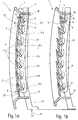
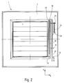
- a closure device 1 shown in Figure 1 comprises a frame 3 and a plurality of slats 5 mounted in the frame.
- Each of the slats 5 has bearing pins 7 on both longitudinal ends, which engage in recesses provided in the frame. This type of attachment allows the individual slats 5 to pivot about the common longitudinal axis of the journal 7.
- 5 levers 9 are attached to the rear side of the fins facing the fan side I, which have lever pins 11 at their end remote from the fins. These lever pins run transversely to the lever 9 and essentially parallel to the adjacent bearing pin 7.
- a slide 15 which extends transversely to the longitudinal direction of the slats.
- recesses 17 are provided in the slide 15, which are of different sizes.
- the recess 17. 1 on a slide end 19 is merely designed as a bore, the diameter of which essentially corresponds to that of the lever pin 11.
- the recess 17.7 is designed as an elongated hole.
- the recesses 17.2 to 17.6 in between are also designed as elongated holes, the longitudinal dimension increasing from recess to recess.
- FIG. 1 shows part-circular regions 22, which are also shown in broken lines. These are recesses in the frame 3, in which the lever pins 11 of the slats 5 engage and are guided when pivoting. For this purpose, these recesses extend on an arc around the pivot axis of the slats. The two Longitudinal ends of the recesses also serve as stops and thus define the two end positions of the slats and also offer lateral guidance.
- the slide 15 is U-shaped, one leg 23 being guided in a groove 25 of the frame 3.
- the other leg 27 of the slider 15 is also guided by two extensions 29, 31 attached to the frame.
- the extension 29 also serves as an abutment for a return device, preferably a return spring 33, which is attached to a bracket 35 attached to the leg 27.
- the reset device 33 is dimensioned so that it supports the closing operation.
- webs 36 extending transversely to the longitudinal direction of the leg 23 are formed on one of the side walls forming the groove 25.
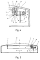
- FIGS. 3 and 4 show the cross-section of the closure device to illustrate the structure.
- the lamella 5 is pivotally mounted in corresponding recesses of the housing 3 by means of the bearing pin 7.
- the lever 9 is attached, which extends perpendicular to the slat.
- the lever pin 11 is attached, which passes through the recess 22 serving as a guide in the housing 3 and ends in the recess 17 in a leg 23 of the slide 15.
- the slide 15, that is to say the leg 23, is guided in the groove 25, which is formed by two wall parts 37, 39 of the housing 3.
- the leg 23 extending in the groove preferably has a plurality of bead-like projections 41 which are directed towards the wall part 39. This can avoid that the entire side surface of the leg 23 rests on the wall part 39.
- a further improvement is provided by the webs 36 already mentioned, which are provided on the wall part 37.
- Figure 3 also clearly shows that the shape of the frame 3 has a curvature 43 to the outside.
- the curvature 43 extends — referring to FIG. 2- in the x direction.
- a curvature in the y direction corresponding to the curvature of the lamellae can, however, be additionally or alternatively provided. In the exemplary embodiment shown, the curvature of the lamellae only runs in the y direction.
- the closed position is shown in FIG.
- the slats 5 form a closed curved surface, with adjacent slats overlapping. Due to the curvature, the top lamella 5.1 in the figure has an angle ⁇ with respect to the vertical, while the bottom lamella 5.7 forms an entirely different angle ⁇ with the vertical.
- the angles of the other slats 5.2 to 5.6 lie within the range spanned by the two angles ⁇ and ⁇ .
- the slats 5 should all include the same angle to the vertical in the open state, the uppermost slat 5.1 must therefore be pivoted through a larger angle of rotation than the lowest slat 5.7.
- the recesses 17, in which the lever pins 11 engage are dimensioned differently.
- the recess 11 is formed as a bore so that the bearing pin 11 engages without play. This ensures a direct conversion of a slide movement of the slide 15 into a tilting movement of this lamella.
- the recess 17 is designed as an elongated hole.
- the slat 5.7 only executes a tilting movement after a certain slide travel. This means that when the lever is moved in the direction of the arrow 46, the slat 5.1 is actuated first, then the adjacent slat 5.2 and so on, and finally the slat 5.7.
- Both the opening position of the slats and the aforementioned end position are defined by the recesses 22, which in addition to their guiding function also serve as stops.
- the slats 5 are closed in the reverse manner, the slat 5.1 being moved first and the lowest slat 5.7 only at the end.
- the slide 15 can be actuated automatically or manually.
Landscapes
- Engineering & Computer Science (AREA)
- Chemical & Material Sciences (AREA)
- Combustion & Propulsion (AREA)
- Mechanical Engineering (AREA)
- General Engineering & Computer Science (AREA)
- Specific Sealing Or Ventilating Devices For Doors And Windows (AREA)
- Air-Flow Control Members (AREA)
- Cooling Or The Like Of Electrical Apparatus (AREA)
- Blinds (AREA)
Applications Claiming Priority (2)
| Application Number | Priority Date | Filing Date | Title |
|---|---|---|---|
| DE19528302A DE19528302C2 (de) | 1995-08-02 | 1995-08-02 | Verschlußvorrichtung für eine lufttechnische Einrichtung |
| DE19528302 | 1995-08-02 |
Publications (3)
| Publication Number | Publication Date |
|---|---|
| EP0757213A2 true EP0757213A2 (fr) | 1997-02-05 |
| EP0757213A3 EP0757213A3 (fr) | 2000-11-15 |
| EP0757213B1 EP0757213B1 (fr) | 2003-05-14 |
Family
ID=7768456
Family Applications (1)
| Application Number | Title | Priority Date | Filing Date |
|---|---|---|---|
| EP96109913A Expired - Lifetime EP0757213B1 (fr) | 1995-08-02 | 1996-06-20 | Dispositif de fermeture pour un appareil de ventilation |
Country Status (3)
| Country | Link |
|---|---|
| EP (1) | EP0757213B1 (fr) |
| AT (1) | ATE240495T1 (fr) |
| DE (2) | DE19528302C2 (fr) |
Cited By (1)
| Publication number | Priority date | Publication date | Assignee | Title |
|---|---|---|---|---|
| WO1999064793A1 (fr) * | 1998-06-10 | 1999-12-16 | ABB Fläkt Oy | Grille de sortie d'air |
Families Citing this family (9)
| Publication number | Priority date | Publication date | Assignee | Title |
|---|---|---|---|---|
| DE19742730B4 (de) * | 1996-09-27 | 2006-03-02 | Valeo Thermique Moteur | Vorrichtung zur Regulierung eines Luftstroms, insbesondere für einen Wärmetauscher eines Kraftfahrzeugs |
| DE19826325C2 (de) * | 1998-06-12 | 2001-03-08 | Schako Metallwarenfabrik | Gitter für einen Luftauslass |
| DE20100740U1 (de) | 2001-01-16 | 2001-05-31 | TRW Automotive Electronics & Components GmbH & Co.KG, 67677 Enkenbach-Alsenborn | Luft-Ausströmer, insbesondere zur Fahrzeugklimatisierung |
| DE102008061054A1 (de) * | 2008-12-08 | 2010-06-17 | Röchling Automotive AG & Co. KG | Luftklappenantrieb |
| DE102009038428B4 (de) * | 2009-08-21 | 2013-04-25 | Audi Ag | Vorrichtung zum Öffnen und Schließen einer Luftleitvorrichtung für ein Kraftfahrzeug |
| DE202019104394U1 (de) | 2019-08-09 | 2019-08-16 | Illinois Tool Works Inc. | Koppelstange zum Manipulieren von in einem Luftausströmer für Fahrzeuge zum Einsatz kommenden Luftleitlamellen, Luftausströmer für ein Fahrzeug sowie Luftausströmersystem |
| RU195258U1 (ru) * | 2019-10-25 | 2020-01-21 | Акционерное общество "Тион Умный микроклимат" | Решетка для организации вентиляционного канала |
| DE102021204015A1 (de) | 2021-04-22 | 2022-10-27 | Maico Elektroapparate-Fabrik Gesellschaft mit beschränkter Haftung | Stellventil, insbesondere für eine Lüftungseinrichtung, Verfahren zum Betreiben eines Stellventils sowie Lüftungseinrichtung mit einem Stellventil |
| DE102021213286A1 (de) | 2021-11-25 | 2023-05-25 | Maico Elektroapparate-Fabrik Gesellschaft mit beschränkter Haftung | Stellventil, insbesondere für eine Lüftungseinrichtung, Verfahren zum Betreiben eines Stellventils sowie Lüftungseinrichtung mit einem Stellventil |
Family Cites Families (6)
| Publication number | Priority date | Publication date | Assignee | Title |
|---|---|---|---|---|
| DE7202132U (de) * | 1972-04-06 | Gebr Trox Gmbh | Vorrichtung zur Einstellung strömender Medien, insbesondere Luft in Luftungs oder Klimaanlagen | |
| FR470588A (fr) * | 1914-04-07 | 1914-09-17 | Seraphin Guzzi | Mécanisme pour aviateur |
| US2293065A (en) * | 1939-06-26 | 1942-08-18 | Maurice D Kiczales | Air flow control damper |
| US4653384A (en) * | 1985-12-31 | 1987-03-31 | Kabushiki Kaisha Toshiba | Air supply adjusting mechanism for air conditioner |
| DE3909297A1 (de) * | 1989-03-21 | 1990-09-27 | Eternit Ag | Belueftungsvorrichtung zum einbau in ein tonnenfoermig gewoelbtes lichtband |
| NL9001436A (nl) * | 1990-06-22 | 1992-01-16 | Hubertus Gerardus Jacobus Peet | Ventilatieluik. |
-
1995
- 1995-08-02 DE DE19528302A patent/DE19528302C2/de not_active Expired - Fee Related
-
1996
- 1996-06-20 EP EP96109913A patent/EP0757213B1/fr not_active Expired - Lifetime
- 1996-06-20 AT AT96109913T patent/ATE240495T1/de not_active IP Right Cessation
- 1996-06-20 DE DE59610435T patent/DE59610435D1/de not_active Expired - Fee Related
Cited By (1)
| Publication number | Priority date | Publication date | Assignee | Title |
|---|---|---|---|---|
| WO1999064793A1 (fr) * | 1998-06-10 | 1999-12-16 | ABB Fläkt Oy | Grille de sortie d'air |
Also Published As
| Publication number | Publication date |
|---|---|
| ATE240495T1 (de) | 2003-05-15 |
| EP0757213B1 (fr) | 2003-05-14 |
| DE19528302A1 (de) | 1997-02-06 |
| EP0757213A3 (fr) | 2000-11-15 |
| DE59610435D1 (de) | 2003-06-18 |
| DE19528302C2 (de) | 2000-08-24 |
Similar Documents
| Publication | Publication Date | Title |
|---|---|---|
| DE69731668T2 (de) | Bedienungsstab für bedeckungen von gebäudeöffnungen | |
| DE60101923T2 (de) | Kabelkanalsystemscharnieranordnung | |
| DE2730393A1 (de) | Automatische plinthe | |
| DE102017206449B4 (de) | Wohnwagenfenster und Öffnungsmechanismus dafür | |
| DE69829979T3 (de) | Verfahren zum öffnen und schliessen einer öffnungsfähigen dachherstellung für ein fahrzeug mit einer öffnung im festen dach, sowie solche öffnungsfähige dachherstellung | |
| DE3118823C2 (de) | Lüftungsvorrichtung | |
| DE202018006765U1 (de) | Wohnwagenfenster und Öffnungsmechanismus dafür | |
| DE102020131095A1 (de) | Lüftungseinrichtung | |
| EP0757213A2 (fr) | Dispositif de fermeture pour un appareil de ventilation | |
| DE68901930T2 (de) | Luefter. | |
| DE19826420A1 (de) | Verschlußeinrichtung für Fenster, Türen o. dgl. Öffnungen | |
| DE60030904T2 (de) | Konstruktion eines öffnungsfähigen Fahrzeugdaches | |
| EP1127992B1 (fr) | Toit à lamelles | |
| DE4020334C2 (de) | Wand- oder Dachelement mit einem rahmenartigen Traggestell und verschwenkbar gehalterten, plattenartigen Lamellen | |
| DE3017483C2 (de) | Verriegelungsvorrichtung zum Verhindern des Aushängens des Ausstellarms einer Ausstellvorrichtung | |
| DE102007023007B3 (de) | Lamellendach | |
| DE4115220C2 (fr) | ||
| DE102009031686A1 (de) | Verschliessmechanismus zum Verriegeln von Schubladen in Fahrzeugen | |
| EP1310395A2 (fr) | Système de coulissement pour fermer et ouvrir une ouverture de toit | |
| EP0971091A2 (fr) | Ensemble d'articulation pour l'actionnement d'un volet ou similaire | |
| DE102024110832A1 (de) | Lüftungsbaugruppe und luftlenkende leitfläche derselben | |
| DE1780283C3 (de) | Dachentlüftungsklappe oder -fenster für Kraftfahrzeuge | |
| EP1340863A1 (fr) | Toit a lamelles | |
| DE69900423T2 (de) | Vormontiertes und voreingestelltes Sektionaltor, und seine Konditionierung | |
| DE102013111566A1 (de) | Windabweiser |
Legal Events
| Date | Code | Title | Description |
|---|---|---|---|
| PUAI | Public reference made under article 153(3) epc to a published international application that has entered the european phase |
Free format text: ORIGINAL CODE: 0009012 |
|
| AK | Designated contracting states |
Kind code of ref document: A2 Designated state(s): AT BE CH DE DK ES FR GB IT LI LU NL SE |
|
| PUAL | Search report despatched |
Free format text: ORIGINAL CODE: 0009013 |
|
| AK | Designated contracting states |
Kind code of ref document: A3 Designated state(s): AT BE CH DE DK ES FR GB IT LI LU NL SE |
|
| RIC1 | Information provided on ipc code assigned before grant |
Free format text: 7F 24F 13/075 A, 7F 24F 13/15 B |
|
| 17P | Request for examination filed |
Effective date: 20001020 |
|
| GRAH | Despatch of communication of intention to grant a patent |
Free format text: ORIGINAL CODE: EPIDOS IGRA |
|
| GRAH | Despatch of communication of intention to grant a patent |
Free format text: ORIGINAL CODE: EPIDOS IGRA |
|
| GRAA | (expected) grant |
Free format text: ORIGINAL CODE: 0009210 |
|
| AK | Designated contracting states |
Designated state(s): AT BE CH DE DK ES FR GB IT LI LU NL SE |
|
| PG25 | Lapsed in a contracting state [announced via postgrant information from national office to epo] |
Ref country code: NL Free format text: LAPSE BECAUSE OF FAILURE TO SUBMIT A TRANSLATION OF THE DESCRIPTION OR TO PAY THE FEE WITHIN THE PRESCRIBED TIME-LIMIT Effective date: 20030514 Ref country code: IT Free format text: LAPSE BECAUSE OF FAILURE TO SUBMIT A TRANSLATION OF THE DESCRIPTION OR TO PAY THE FEE WITHIN THE PRE;WARNING: LAPSES OF ITALIAN PATENTS WITH EFFECTIVE DATE BEFORE 2007 MAY HAVE OCCURRED AT ANY TIME BEFORE 2007. THE CORRECT EFFECTIVE DATE MAY BE DIFFERENT FROM THE ONE RECORDED.SCRIBED TIME-LIMIT Effective date: 20030514 Ref country code: GB Free format text: LAPSE BECAUSE OF FAILURE TO SUBMIT A TRANSLATION OF THE DESCRIPTION OR TO PAY THE FEE WITHIN THE PRESCRIBED TIME-LIMIT Effective date: 20030514 Ref country code: FR Free format text: LAPSE BECAUSE OF FAILURE TO SUBMIT A TRANSLATION OF THE DESCRIPTION OR TO PAY THE FEE WITHIN THE PRESCRIBED TIME-LIMIT Effective date: 20030514 |
|
| REG | Reference to a national code |
Ref country code: GB Ref legal event code: FG4D Free format text: NOT ENGLISH |
|
| REG | Reference to a national code |
Ref country code: CH Ref legal event code: EP |
|
| REG | Reference to a national code |
Ref country code: CH Ref legal event code: NV Representative=s name: SAEGER & PARTNER |
|
| REF | Corresponds to: |
Ref document number: 59610435 Country of ref document: DE Date of ref document: 20030618 Kind code of ref document: P |
|
| PG25 | Lapsed in a contracting state [announced via postgrant information from national office to epo] |
Ref country code: LU Free format text: LAPSE BECAUSE OF NON-PAYMENT OF DUE FEES Effective date: 20030620 |
|
| PG25 | Lapsed in a contracting state [announced via postgrant information from national office to epo] |
Ref country code: BE Free format text: LAPSE BECAUSE OF NON-PAYMENT OF DUE FEES Effective date: 20030630 |
|
| PG25 | Lapsed in a contracting state [announced via postgrant information from national office to epo] |
Ref country code: SE Free format text: LAPSE BECAUSE OF FAILURE TO SUBMIT A TRANSLATION OF THE DESCRIPTION OR TO PAY THE FEE WITHIN THE PRESCRIBED TIME-LIMIT Effective date: 20030814 Ref country code: DK Free format text: LAPSE BECAUSE OF FAILURE TO SUBMIT A TRANSLATION OF THE DESCRIPTION OR TO PAY THE FEE WITHIN THE PRESCRIBED TIME-LIMIT Effective date: 20030814 |
|
| PG25 | Lapsed in a contracting state [announced via postgrant information from national office to epo] |
Ref country code: ES Free format text: LAPSE BECAUSE OF FAILURE TO SUBMIT A TRANSLATION OF THE DESCRIPTION OR TO PAY THE FEE WITHIN THE PRESCRIBED TIME-LIMIT Effective date: 20030825 |
|
| NLV1 | Nl: lapsed or annulled due to failure to fulfill the requirements of art. 29p and 29m of the patents act | ||
| GBV | Gb: ep patent (uk) treated as always having been void in accordance with gb section 77(7)/1977 [no translation filed] |
Effective date: 20030514 |
|
| BERE | Be: lapsed |
Owner name: *MAICO ELEKTROAPPARATE-FABRIK G.M.B.H. Effective date: 20030630 |
|
| PLBE | No opposition filed within time limit |
Free format text: ORIGINAL CODE: 0009261 |
|
| STAA | Information on the status of an ep patent application or granted ep patent |
Free format text: STATUS: NO OPPOSITION FILED WITHIN TIME LIMIT |
|
| 26N | No opposition filed |
Effective date: 20040217 |
|
| EN | Fr: translation not filed | ||
| PGFP | Annual fee paid to national office [announced via postgrant information from national office to epo] |
Ref country code: AT Payment date: 20070510 Year of fee payment: 12 |
|
| PGFP | Annual fee paid to national office [announced via postgrant information from national office to epo] |
Ref country code: CH Payment date: 20070523 Year of fee payment: 12 |
|
| PGFP | Annual fee paid to national office [announced via postgrant information from national office to epo] |
Ref country code: DE Payment date: 20070627 Year of fee payment: 12 |
|
| REG | Reference to a national code |
Ref country code: CH Ref legal event code: PL |
|
| PG25 | Lapsed in a contracting state [announced via postgrant information from national office to epo] |
Ref country code: DE Free format text: LAPSE BECAUSE OF NON-PAYMENT OF DUE FEES Effective date: 20090101 Ref country code: AT Free format text: LAPSE BECAUSE OF NON-PAYMENT OF DUE FEES Effective date: 20080620 |
|
| PG25 | Lapsed in a contracting state [announced via postgrant information from national office to epo] |
Ref country code: LI Free format text: LAPSE BECAUSE OF NON-PAYMENT OF DUE FEES Effective date: 20080630 Ref country code: CH Free format text: LAPSE BECAUSE OF NON-PAYMENT OF DUE FEES Effective date: 20080630 |