EP0757632B1 - Dispositif a detecteur pour la commande de systemes de ventilation dans des vehicules - Google Patents
Dispositif a detecteur pour la commande de systemes de ventilation dans des vehicules Download PDFInfo
- Publication number
- EP0757632B1 EP0757632B1 EP95905112A EP95905112A EP0757632B1 EP 0757632 B1 EP0757632 B1 EP 0757632B1 EP 95905112 A EP95905112 A EP 95905112A EP 95905112 A EP95905112 A EP 95905112A EP 0757632 B1 EP0757632 B1 EP 0757632B1
- Authority
- EP
- European Patent Office
- Prior art keywords
- gas sensor
- gas
- sensor arrangement
- arrangement according
- signal
- Prior art date
- Legal status (The legal status is an assumption and is not a legal conclusion. Google has not performed a legal analysis and makes no representation as to the accuracy of the status listed.)
- Expired - Lifetime
Links
Images


Classifications
-
- G—PHYSICS
- G05—CONTROLLING; REGULATING
- G05D—SYSTEMS FOR CONTROLLING OR REGULATING NON-ELECTRIC VARIABLES
- G05D27/00—Simultaneous control of variables covered by two or more of main groups G05D1/00 - G05D25/00
- G05D27/02—Simultaneous control of variables covered by two or more of main groups G05D1/00 - G05D25/00 characterised by the use of electric means
-
- B—PERFORMING OPERATIONS; TRANSPORTING
- B60—VEHICLES IN GENERAL
- B60H—ARRANGEMENTS OF HEATING, COOLING, VENTILATING OR OTHER AIR-TREATING DEVICES SPECIALLY ADAPTED FOR PASSENGER OR GOODS SPACES OF VEHICLES
- B60H1/00—Heating, cooling or ventilating devices
- B60H1/00642—Control systems or circuits; Control members or indication devices for heating, cooling or ventilating devices
- B60H1/00735—Control systems or circuits characterised by their input, i.e. by the detection, measurement or calculation of particular conditions, e.g. signal treatment, dynamic models
- B60H1/008—Control systems or circuits characterised by their input, i.e. by the detection, measurement or calculation of particular conditions, e.g. signal treatment, dynamic models the input being air quality
-
- B—PERFORMING OPERATIONS; TRANSPORTING
- B60—VEHICLES IN GENERAL
- B60H—ARRANGEMENTS OF HEATING, COOLING, VENTILATING OR OTHER AIR-TREATING DEVICES SPECIALLY ADAPTED FOR PASSENGER OR GOODS SPACES OF VEHICLES
- B60H3/00—Other air-treating devices
- B60H3/0085—Smell or pollution preventing arrangements
-
- G—PHYSICS
- G01—MEASURING; TESTING
- G01N—INVESTIGATING OR ANALYSING MATERIALS BY DETERMINING THEIR CHEMICAL OR PHYSICAL PROPERTIES
- G01N33/00—Investigating or analysing materials by specific methods not covered by groups G01N1/00 - G01N31/00
- G01N33/0004—Gaseous mixtures, e.g. polluted air
- G01N33/0009—General constructional details of gas analysers, e.g. portable test equipment
- G01N33/0027—General constructional details of gas analysers, e.g. portable test equipment concerning the detector
- G01N33/0036—General constructional details of gas analysers, e.g. portable test equipment concerning the detector specially adapted to detect a particular component
- G01N33/0059—Avoiding interference of a gas with the gas to be measured
-
- E—FIXED CONSTRUCTIONS
- E21—EARTH OR ROCK DRILLING; MINING
- E21B—EARTH OR ROCK DRILLING; OBTAINING OIL, GAS, WATER, SOLUBLE OR MELTABLE MATERIALS OR A SLURRY OF MINERALS FROM WELLS
- E21B2200/00—Special features related to earth drilling for obtaining oil, gas or water
- E21B2200/22—Fuzzy logic, artificial intelligence, neural networks or the like
Definitions
- the invention relates to a sensor arrangement for Control of ventilation systems in vehicles in conversion or in supply air operation depending on the pollutant concentration in the air outside the vehicle, with a Gas sensor element, the electrical resistance of which occurs reducing gases decrease and oxidizing when they occur Gases rise, and an evaluation unit, the output of which is connected to the control of the ventilation system.
- gas sensor elements e.g. Tin dioxide sensor elements
- the presence of oxidizable gases can be detected, e.g. the presence of carbon monoxide, Hydrocarbons and hydrogen.
- a gas-sensitive layer of the gas sensor element the for example from electrically conductive and heated tin dioxide can exist, reduced by the oxidizable gas; this results in a reduction in the ohmic resistance the gas-sensitive tin dioxide layer of the gas sensor element.
- gas sensor elements are used in sensor arrangements for controlling ventilation systems in vehicles used. Whenever the vehicle is an area reached with a high concentration of pollutants Ventilation system of the vehicle switched to recirculation mode, so that the pollutants from the passenger cabin of the vehicle be kept away.
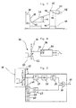
- Figure 1 shows a sensor circuit that a heated Gas sensor element 1 and an external resistor 2 having.
- the external resistor 2 can also be provided by a constant current source be replaced.
- the between the heated Gas sensor element 1 and the external resistance 2 tapped Divider voltage UM is a function of itself Gas loading changing ohmic resistance of the heated gas sensor element 1.
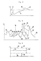
- Figure 2 shows the change in ohmic resistance of the gas sensor element 1 if this only with reducing or only with oxidizing gases.
- the pulse 3 shown in the figure is the result of a Exposure of the gas sensor element to oxidizable gases, e.g. with carbon monoxide (CO).
- Impulse 4 is the result an exposure to the gas sensor element 1 reducible gases, e.g. with nitrogen oxides (NOx).
- FIG. 3 The so-called “masking effect” is shown in FIG. 3; the Pulse 5 is caused by an action on the gas sensor element 1 with oxidizable and thus reducing carbon monoxide causes.
- the nitrogen oxides in the mixed gas remain the ohmic resistance of the gas sensor element lower than in it unstressed condition.
- the Despite the presence of reducible and thus oxidizing nitrogen oxides in Diesel exhaust remains the ohmic resistance of the gas sensor elements 1 below the level he is in has no pollution from exhaust gases. This effect occurs due to the oxidizable also contained in the diesel exhaust and thus reducing gases.
- the tin dioxide layer of the gas sensor element has a lower resistance and purely offered reducible and oxidizing gases Make the tin dioxide layer of the gas sensor element more resistive, So far it has been assumed that for meaningful control of ventilation systems in vehicles in recirculation or supply air mode two gas sensor elements are required. It serves a gas sensor element for the detection of oxidizable and thus reducing gases, whereas the other gas sensor element for the detection of reducible and thus oxidizing gases serves.
- Such sensor arrangements equipped with two gas sensor elements for controlling ventilation systems in vehicles are comparatively complex. This arises initially from the presence of two gas sensor elements. About that in addition, those emitted by these two gas sensor elements Gas sensor signals processed and in a more suitable Form for evaluation are linked together, which results in a comparatively complicated configuration the processing and evaluation unit results.
- the invention has for its object a sensor arrangement for controlling ventilation systems in vehicles in Circulating or in the supply air operation depending on the pollutant concentration to create in the air outside of the vehicle where both the sensors and the evaluation can be made simpler and thus less complex.
- This task is for the sensor arrangement described above solved according to the invention in that the sensor arrangement is designed so that the rise of one in the Evaluation unit input gas sensor signal with an increase the concentration of reducing gases such as the drop in the gas sensor signal input into the evaluation unit with a corresponding increase in concentration oxidizing gases equals that the evaluation unit the increase from the gas sensor signal entered into it or the decrease of the same per unit of time and that the evaluation unit a switching signal for adjusting the Ventilation system in the recirculation mode generated as soon as the determined Rise or fall of the gas sensor signal per unit of time amount a defined value or threshold exceeds.
- the fact is used that in ventilation systems in vehicles normally with impulses the air with pollutants or harmful gases must be expected and that static conditions in the the air surrounding the vehicle does not normally occur, since at least the vehicle is in relation to the surrounding area Air moves.
- Sensor arrangement a typical behavior of a gas sensor element used, which is that the gas sensor element upon exposure to a gas in the adsorption phase typically responds relatively quickly, whereas the reaction in the desorption phase, in the course of it the gas sensor element is in its original state reached again, takes three to five times as long.
- the vehicle's ventilation system is switched to recirculation mode in the desired manner, if the rise or fall of the gas sensor signal a predefined threshold value per unit of time exceeds. It is irrelevant whether the gas sensor signal increases or decreases because of the steepness of the increase or amount of waste and with the Threshold is compared. This is the threshold exceeded, the switching signal for switching the ventilation system in the recirculation mode.
- the evaluation unit the switching signal is only generated when the calculated one Rise or fall of the gas sensor signal per unit of time the amount over a predefinable period Threshold exceeds.
- the switching behavior of the ventilation system sought according to the invention can be reached with comparatively little effort, if the evaluation unit has a bandpass, that only lets an amplitude spectrum pass, which represents an increase or Indicates drop in the gas sensor signal per unit of time above which the gas sensor signal is routed to such Rise or fall of the gas sensor signal per unit of time to determine, and its output signal to generate the Switching signals used to control the ventilation system becomes.
- the switching behavior sought according to the invention achievable if the evaluation unit is a computing device to perform a Fourrier transform has, in which the gas sensor signal arithmetically on the Presence of a certain one, the threshold Exceeding rise or fall of the gas sensor signal each Time unit indicating amplitude spectrum is examined, and with the switching signal for in the evaluation unit the control of the ventilation system is generated when in Gas sensor signal determined such an amplitude spectrum becomes.
- the evaluation unit is an electronic neural Network in which the gas sensor signal after Features on the presence of a threshold Exceeding rise or fall of the gas sensor signal each Unit of time is examined, and in the evaluation unit the switching signal is generated when during this examination an increase or decrease in the Gas sensor signal is determined per unit of time.
- the electronic neural network as a three- or multilayer feedforward neural Train network. Both current and also gas sensor signals that are further back or from these Gas sensor signals calculated signals as an input variable serve. The output of this neural network provides then that required to control the ventilation system Switching signal.
- a feedforward three or more layers neural network can also be compared with Results a three- or multi-layer feedback loop neural network can be used.
- the evaluation unit can then have an electronic FUZZY logic unit, by means of the threshold value in the gas sensor signal Excessive rise or fall of the gas sensor signal each Unit of time is detectable, which in the evaluation unit Switching signal is generated when on during this examination the increase or decrease in the threshold value Gas sensor signal is determined per unit of time.
- the evaluation unit is expediently designed such that that the switching signal goes out when the gas sensor signal is inside of the band assigned to the mean value formed lies and in the gas sensor signal none the threshold Exceeding rise or fall of the gas sensor signal each Amplitude spectrum indicating time unit is determined. This ensures that the ventilation system of the Vehicle always works in recirculation mode when the Pollutant content in the air surrounding the vehicle is not permitted is high and if an impermissibly high increase in the pollutant content of the air surrounding the vehicle.
- the evaluation unit of the invention Sensor arrangement a storage device in which Slope reversal points of the gas sensor signal are stored, the switching signal on the output side of the evaluation unit goes off if the gas sensor signal does not reach a slope reversal point a certain predeterminable signal difference to the slope reversal point and the gas sensor signal within the band assigned to the mean formed lies.
- the sensitivity of the sensor arrangement the driving situation and the conditions found adapt.
- the sensor arrangement according to the invention should therefore be used in areas with mostly clean air extremely sensitive to detected Pollutants react, whereas responsiveness lowered the sensor arrangement according to the invention must be if the vehicle is predominantly in areas drives in which the pollutant levels of the outside air and thus the frequency of the pollutant peaks to be found is very large.
- the sensor arrangement according to the invention is urgently necessary to a ratio between the operating time of the Ventilation system in recirculation mode and the operating time of the To achieve ventilation system in the supply air mode, which also when driving in heavily polluted outside air never more than about 50% of the total time the ventilation system in recirculation mode located.
- This is the only way to achieve that released by the vehicle occupants in the interior of the vehicle Moisture and generated by the vehicle occupants Smells and the like reliably from the interior of the vehicle be driven out.
- Mode of operation prevents that by operating too long the ventilation system in recirculation mode the oxygen percentage inside the motor vehicle to values could drop, which is questionable from a medical point of view are.
- the pollution the air divides into the basic load for example prevails in a city or region, and the pollutant peaks that come from others, vehicles in front are generated.
- the basic burden is regularly in rural or suburban Districts be lower than in densely populated inner city regions.
- the evaluation unit a control device for changing the sensitivity the sensor arrangement, by means of the sensitivity of the sensor arrangement with increasing or falling frequency from the threshold value Rise or fall of the gas sensor signals each Unit of time can be reduced or increased, the amount the changes in the sensitivity of the sensor arrangement is limited per unit of time.
- the sensor arrangement can be structurally less complex Be realized when the evaluation unit a Time measuring device, by means of which the operating times of the ventilation system can be recorded in the supply air and recirculation mode, a computing device by means of which the quotient from the Operating time in the supply air mode and the operating time in the recirculation mode is calculable, and has a control device, by means of the responsiveness of the sensor arrangement reduced with increasing recirculation mode and at increasing supply air operation is increased, the amount of Change in the sensitivity of the sensor arrangement is limited per unit of time.
- the control device has sensitivity to change the response sensitivity of the sensor arrangement an outside temperature sensor that measures the air temperature outside of the vehicle detects an interior temperature sensor which senses the air temperature within the vehicle, and a Comparison device on which of the outside temperature sensor Entered outside air temperature with the one from the inside temperature sensor compares the internal air temperature entered, the control device being responsive the sensor arrangement increases or decreases when the external air temperature is greater or less than the internal one Air temperature.
- the evaluation unit with the control of the ventilation system can be programmed as a central microprocessor or analog be trained.
- Coming gas sensor element can be used as a metal dioxide gas sensor element be trained.
- the known tin dioxide gas sensor elements are designed that their responsiveness to oxidizable gases is particularly pronounced while their responsiveness compared to reducible gases.
- this must be so be designed to be oxidizable and reducible Gases are sensitive to about the same extent. This leads to the sensor arrangements known from the prior art to the fact that these sensor arrangements are particularly susceptible to are the masking effect already described above.
- the gas sensor element for use in the gas sensor arrangement according to the invention is the gas sensor element as a mixed oxide sensor element formed, the gas-sensitive layer of tin dioxide (SnO2), tungsten trioxide (WO3), iron oxide (Fe2O3), Aluminum oxide (Al2O3) and platinum as a reaction accelerator (Pt) and palladium (Pd) contains.
- SnO2 tin dioxide
- WO3 tungsten trioxide
- Fe2O3 iron oxide
- Al2O3 Aluminum oxide
- platinum platinum as a reaction accelerator (Pt) and palladium (Pd) contains.
- the mixed oxide sensor element has particularly advantageous properties, if its gas sensitive layer 29 to 49, preferably about 39% tin dioxide (SnO2), 7 to 13, preferably 10% iron oxide (Fe2O3), 28 to 48, preferably 38, % Tungsten trioxide (WO3), 7 to 13, preferably 10,% aluminum oxide (Al2O3), 1 to 3, preferably 2,% palladium (Pd) and 0.5 to 1.5, preferably 1,% platinum (Pt) contains.
- SnO2 tin dioxide
- Fe2O3 iron oxide
- WO3 % Tungsten trioxide
- Al2O3 aluminum oxide
- Pd palladium
- Pt 1,% platinum
- the gas sensor element can directly on an electrical Printed circuit board applied and using precious metal wires be connected to the circuit board.
- the gas sensor element electrically contacted with platinum wires and in a recess of an electrical circuit board of the evaluation unit inserted at about the same level as this and are gas sensor element connections directly to the circuit board welded on, so that the gas sensor element is freely suspended is.
- Metal oxide gas sensor elements change their characteristics, when the temperature on the sensor element surface changed.
- When used in the sensor arrangement according to the invention need the metal oxide gas sensor elements and so whose sensor element surface exposed to the outside air become. This leads to the problem that at high Driving speeds a direct exposure to air would cool the sensor element surface inadmissible.
- the metal oxide gas sensor element has been proposed to solve this problem with a labyrinth, which is arranged and designed so that on the one hand the outside air reaches the metal oxide gas sensor element, on the other hand however, the metal oxide gas sensor element is sufficient protected against moisture, dirt particles and air currents is.
- a disadvantage of such a configuration is that the path of the outside air through the labyrinth Response speed of the metal oxide gas sensor element slows down will and that different gases at the comparatively adsorb large surface of the labyrinth.
- Such gas permeable barriers are conventional formed as stretched membranes, which, provided that Air currents are exposed to vibrations become. As a result, air movements in the metal oxide gas sensor element surrounding area that creates a Change in temperature at the sensor element surface Have consequence. To such changes in temperature The metal oxide gas sensor element reacts to the sensor element surface with a change in its electrical resistance, so that the gas sensor signal is impermissible with a Disturbance variable is superimposed.
- the wall of the chamber can advantageously be at least partially manufacture from a perforated material that at least a layer of gas-permeable material is dimensionally stable carries and supports mechanically.
- the at least one layer of the gas-permeable is advantageous Material made of plastic film.
- gas e.g. Carbon monoxide or Nitrogen oxide
- the dimensionally stable and gas-permeable wall of the the gas sensor element receiving chamber made of sintered Plastic, glass, metal or the like. is trained.
- Sintered bodies have, depending on the material, a surface, which makes the sintered body almost impervious to water does, whereas it lets gases pass.
- the response behavior of the gas sensor element furthermore advantageous if the gas sensor element receiving chamber is approximately hemispherical.
- the gas sensor element and the evaluation unit are integrated in a housing.
- the actual evaluation The data coming from the sensor module is then often found in the already existing microcomputer in the central heating and air conditioning control unit of the motor vehicle.
- the analog gas sensor signal initially within of the sensor module is processed into a digital signal and as a digital signal of the actual evaluation, the in the microcomputer of the central heating and air conditioning control unit of the motor vehicle takes place, is entered.
- Analog data that is susceptible to interference therefore does not have to be transported be and in the microcomputer of the central heating and Air conditioning control unit is not a complex analog / digital conversion required.
- the ohmic resistance of the gas sensor element component is an oscillating circuit and of a medium frequency AC voltage is flowed through.
- the frequency of the oscillating circuit is preferably determined by creates a capacitor.
- the oscillating circuit has a timer module, which is connected to a frequency-determining capacitor and has a feedback branch in which the resistor of the gas sensor element and a second resistor and the resistance of the gas sensor element has a parallel branch in which a third resistor is arranged.
- the ratios of the resistance of the gas sensor element, of the resistance connected in series with this and the resistance connected in parallel with the former are chosen so that even with extreme low impedance or with extreme high impedance of the gas sensor element or whose ohmic resistance is the group resistance of the three Resistances are always within the easy-to-calculate range remains what is directly related to the frequency of the Gas sensor signal relates. This ensures that the frequency of the gas sensor signal never in a range can move the outside of the recording area of the Gas sensor element downstream evaluation electronics.
- the gas sensor signal is a resistance value in FIG Ohmic resistance R plotted against time t.
- the gas sensor signal assumes the value 7, which results when the outside air is neither oxidizing nor reducing Gases. This value becomes 7 when it occurs oxidizable gases with a large negative slope leave how from the course of the gas sensor signal results in phase 8.
- the resistance of the Gas sensor element with low resistance the corresponding to the slope Relationship between the change in resistance and the elapsed time.
- desorption phase 9 On the application of the Gas sensor element with oxidizable gases, which in particular contained in gasoline exhaust gases follows a so-called desorption phase 9, in which the gas sensor element by unloaded Outside air is moved and during which the gas sensor element desorbed. This desorption phase lasts until to which the gas sensor signal returns its value 7 for has reached unpolluted air.
- the positive slope of the gas sensor signal is significant less than the negative slope of the gas sensor signal during the phase 8, also called the adsorption phase Ratio of change in resistance per unit of time during the desorption phase 9 significantly smaller than during the adsorption phase 8.
- the gas sensor signal After the gas sensor signal returns its unpolluted outside air has taken the corresponding value 7, it goes through Gas sensor element an area in which the outside air with reducible gases is loaded. Because of the exposure of the gas sensor element with these reducible gases follows an adsorption phase 10, in the course of which the resistance value of the gas sensor element due to the oxidizing Effect of the reducible gases is greatly increased. The positive Slope of the gas sensor signal during the adsorption phase 10 corresponds approximately to the negative slope of the gas sensor element during the adsorption phase 8. After the area the outside air loaded with reducible gases a desorption phase 11 begins, in which desorbs the gas-sensitive layer of the gas sensor element. The desorption phase runs in the now unloaded Outside air until the gas sensor signal returns to the original Has taken value 7.
- the slope of the gas sensor signal is during the adsorption phase a gas sensor element charged with oxidizable gases and during the desorption phase 11 one Gas sensor element loaded with reducible gases negative; this slope is positive during the desorption phase 9 of a gas sensor element charged with oxidizable gases and with one during the adsorption phase 10 reducible gases acted upon gas sensor element.
- the gas sensor element is made from gasoline exhaust gases originating oxidizable gases, from which the results in a large slope adsorption phase 12.
- a desorption phase follows 13.
- the gas-sensitive desorbs Layer of the gas sensor element the desorption speed is significantly lower than the adsorption rate during the adsorption phase 12. It follows that the negative slope of the gas sensor signal during the desorption phase 13 in terms of amount is less than the positive slope of the gas sensor signal during the adsorption phase 12.
- the gas sensor element with reducible Gases e.g.
- adsorption phase 14 a large slope, the slope of the adsorption phase 14 the amount of the slope of the previous adsorption phase 12 corresponds.
- the adsorption phase 14 differs to the extent of the desorption phase 13 as the slope of the Adsorption phase 14 is significantly larger than that Slope during the desorption phase 13.
- a desorption phase follows 15, a slight application of the gas sensor element with oxidizable gases and the resulting small adsorption phase 16, immediately following a short-term Acting on the gas sensor elements in considerable Height with reducible gases coming from a diesel exhaust Truck can originate, and the resulting Adsorption phase 17, a desorption phase 18, another Treatment with reducible gases leading to the adsorption phase 19 leads, a desorption phase 20, a Exposure to oxidizable gases leading to the adsorption phase 21 leads, an exposure to reducible gases, which leads to the adsorption phase 22, a desorption phase 23, an exposure of the gas sensor element with oxidizable Gases leading to the adsorption phase 24, a desorption phase 25, a renewed application of the gas sensor element with oxidizable gases, which leads to the adsorption phase 26, an action on the gas sensor element with reducible Gases leading to the a
- the representation of the gas sensor signal according to FIG. 5 goes clearly shows that the slope in the adsorption phases is significantly larger than the slope in the desorption phases.
- the principle of the present invention is now based on the slope of the gas sensor signal to prescribe a threshold value, with the result that the vehicle's ventilation system is switched from supply air to recirculation mode whenever the Rise of the gas sensor signal in terms of amount this threshold exceeds.
- a switching signal for switching the ventilation system of the vehicle from supply air to recirculation mode always takes place when the current gas sensor signal outside the band 32 and thus is within ranges 35 or 36.
- the signal for switching the ventilation system from supply air to Recirculation mode must be created at a time from which acceptable to the quality of the air surrounding the vehicle is. To achieve such a switching behavior, is on Recirculation mode switched when - as can be seen in Figure 7 -
- a decrease in the gas sensor signal begins with the negative slope of this descent of the gas sensor signal is greater than that already mentioned above mentioned threshold. This happens before time 37 Gas sensor signal e.g. at its normal value 38 which it is at outside air.
- the gas sensor signal drops up to a reversal point 40 with which the on the adsorption phase 39 following desorption phase 41 begins.
- the Reversal point 40 changes the sign of the slope of the gas sensor signal of a negative sign during the adsorption phase 39 to a positive sign during the Desorption phase 41.
- the reversal point 40 is recognized and stored in an evaluation unit.
- this one Reversal point 40 the gas sensor signal at the time of reversal assigned to the sign of the slope of the gas sensor signals.
- the gas-sensitive was applied Layer of the gas sensor element with an oxidizable Gas.
- the end of the desorption phase 41 is now carried out an exposure to the gas-sensitive layer of the gas sensor element with a reducible gas.
- the slope of the gas sensor signal changes from the comparatively low value during the desorption phase 41 to the comparatively large value during the adsorption phase following time 43 44.
- the slope of the gas sensor signal during the adsorption phase 44 exceeds the predetermined threshold, so that at time 43 a switchover of the ventilation system of the Vehicle from supply air to recirculation mode.
- the Adsorption phase 44 continues after the admission has ended the gas-sensitive layer of the gas sensor element with reducible Gases at a turning point 45 into a desorption phase 46 over.
- the reversal point 45 between the adsorption phase 44 and the desorption phase 46 that changes Sign of the slope of the gas sensor signal.
- the reversal point 45 in the evaluation unit becomes a sign change recognized and then saved. Beyond that the gas sensor signal level 47 at the reversal point 45 in the evaluation unit saved.
- a difference value 48 is stored, which can be freely specified is.
- the difference value 48 for desorption phases 46 after An exposure to reducible gases can be the difference 42 for a desorption phase 41 after an application with oxidizable gases, he can but also differ from this one, because diesel exhaust gases are different are perceived as gasoline emissions.
- Graph 49 shows the operating status of the ventilation system on.
- Graph 49 shows that the ventilation system from time 37 to the switchover to supply air operation after increasing by the difference value 42 in the from the reversal point 40 following desorption phase 41 and between the time 43 and the decrease by the difference value 48 in the the reversal point 45 following desorption phase 46 in recirculation mode has worked.
- the sensor arrangement includes a sensor part 50 and one Evaluation unit 51.
- the sensor part 50 has a gas sensor element 52, which is a changeable Has ohmic resistance and by a heater 53 at an operating temperature below 250 Degree C is maintained. Furthermore, it belongs to the sensor part 50 an external resistor 54. One between the gas sensor element 52 and the external resistor 54 tapped gas sensor signal is through a connecting line 55 in the evaluation unit 51 entered.
- This central evaluation unit 51 serves both to evaluate the connection line 55 entered gas sensor signal as well as for controlling the in Figure 8 not shown ventilation system of the vehicle.
- the evaluation unit 51 has an integrated analog / digital converter 56 on which the analog in the evaluation unit 51 input gas sensor signal into a digital signal converts. Furthermore, the evaluation unit 51 a program sequence is stored digitally, by means of the the switching criteria explained with reference to Figures 4 to 7 a switching signal for switching the ventilation system off the supply air to the recirculation mode and vice versa.
- the gas sensor signal passes through the connecting line 55 into the evaluation unit 51.
- the gas sensor signal is transmitted via a Bandpass 57 performed.
- the bandpass 57 is designed so that only such frequency bands can pass it for you Course of the gas sensor signal are typical when the gas sensor signal corresponding to one on the gas sensor element 52 changing adsorption phase. That is, the Bandpass 57 can only pass those frequency bands that a value exceeding the predetermined threshold Mark the slope of the gas sensor signal.
- the gas sensor element 52 designed in a manner to be described later is that the slope when it is exposed to oxidizable Gases and the resulting adsorption phase equal to the slope when it is loaded with reducible Gases and the resulting adsorption phase is.
- the output signal of the bandpass is in a demodulator 58 57 rectified.
- the rectified output signal of the demodulator 58 triggers one if the size is appropriate Comparator 59 with a freely selectable switching shaft.
- This switching signal is at the output of the comparator 59 as long as long as the gas sensor element 52 of the sensor part 50 is in the adsorption phase. Saturation of the gas sensor element 52 comes almost never in practice before, since the vast majority of the occurring Pollution in the outside air is relatively short-term Nature is what goes back to the fact that in normal operation the motor vehicle is moving in relation to the outside air. Adsorption phases last at most a few Minutes, so the gas sensor element 32 normally does not is brought into a saturated state.
- the ventilation system is forced switched from recirculation to supply air operation, if during this period is not due to the change in pollution a changeover of the outside air surrounding the vehicle the ventilation system from recirculation to supply air operation is done.
- the output signal of the comparator 59 and the output signal of the comparator 63 of the evaluation unit 51 are in a link 64 with each other connected.
- the output signal of logic element 64 is through an output line 65 of the link 64 or the evaluation unit 51 as a switching signal in the Control of the ventilation system entered.
- Sensor arrangement are the circuit functions that above were explained using analog function groups, simulated mathematically. This then results in a microprocessor-controlled Process to, according to the above Desired desired switching behavior, switching signals for switching the ventilation system of the vehicle to get from the supply air to the recirculation mode or vice versa.
- the gas sensor element 52 is advantageous as a mixed oxide sensor element formed, its gas sensitive layer too approx. 39% tin dioxide, approx. 10% iron oxide, approx. 38% tungsten trioxide, approx. 10% aluminum oxide, approx. 2% palladium and approx. Contains 1% platinum, with the palladium and the platinum as Reaction accelerators act.
- the gas sensor element becomes at a temperature operated, which is below 200 degrees C.
- a temperature operated which is below 200 degrees C.
- the sensitivity of the gas sensor element 52 compared to reducible gases is comparable with responsiveness at other temperatures. This ensures that with regard comparable to their potential interference for vehicle occupants Actions on the gas sensor element 52 with reducible and oxidizable gases are roughly the same, albeit in different ones Directional changes in the gas sensor signal occur. Because of this even response of the gas sensor element 52 compared to oxidizable and reducible gases, it is possible to change the Gas sensor signal per unit of time, i.e. the amount of the slope of the gas sensor signal as switching parameters for the ventilation system to use.
- Sensor arrangement are the sensor part 50 and the evaluation unit 51 in an internally common housing arranged.
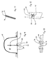
- the gas sensor element is attached to a circuit board 66 and arranged within a chamber 67.
- Chamber 67 is by a wall or shield 68 and by a Horizontal plate 69 formed.
- the horizontal plate 69 has one in its cross section approximately that of the printed circuit board 66 corresponding opening 70 through which the circuit board 66 protrudes into the chamber 67.
- For sealing is between the inner circumference of the opening 70 and the inside opening portion of the circuit board 66 sealing material 71 provided.
- the gas sensor element 52 is attached directly to the circuit board 66, wherein the circuit board 66 is the connection to in FIG produces evaluation unit 51, not shown. With this The evaluation unit 51 is in a separate embodiment Housing housed.
- the chamber 67 and the evaluation unit 51 receiving, not shown in Figure 10 Interior of the housing in question hermetically severed.
- a hermetic separation is required to, for example, the cooldowns of the To minimize gas sensor element 52 and to exclude interference factors, which arise, for example, from outgassing heating electronic components of the evaluation unit 51 or could result in heating of plastic parts.
- the wall or shield 68 which is the gas sensor element 52 accommodating chamber 67 is gas permeable educated. This is an unimpeded and quick gas exchange between the chamber 67 and the wall or Shielding 68 surrounding air is possible.
- the wall 68 has a gas permeable component Slide 72.
- a particularly suitable material for the Teflon has turned out to be a film.
- the film 72 is on both sides through dimensionally stable and perforated wall parts 73, 74 covered and supported. It is between the wall parts 73, 74 clamped so that vibration of the film 72 is prevented in any case.
- the wall parts 73, 74 can, for example, be deep-drawn Molded parts made of wire mesh or as deep-drawn perforated metal or plastic parts.
- the wall or shield 66 can be dome-shaped or hemispherical be formed, with the dimensional stability can be achieved, for example, by a film 72 made of Teflon with glass fiber reinforced plastic to match molded wall or shield 68 pressed becomes.
- the mechanical Protective wall or shield 68 from one gas permeable sintered body or from a gas permeable Plastic body are molded.
- FIGS. 12 and 13 shows the section I - I in FIG. 12.
- the recess 75 is outdoors End portion of that part of the circuit board 66 which in the chamber 67 protrudes.
- the gas sensor element 52 is arranged in the middle area of the recess 75 of the printed circuit board 66 .
- the gas sensor element 52 is by means of connecting wires 76, which are made of platinum or a other suitable precious metal can be formed with Pins 77 connected to the circuit board 66th are provided in the area surrounding the recess 75.
- the gas sensor element 52 is thus held by means of the lead wires 76 and the board-side connector pins 76.
- the connector pins 76 can, for example Be made of nickel.
- the arrangement of the gas sensor element 52 in the recess 75 the circuit board 66 is selected so that the gas sensor element 52 in both the longitudinal, transverse and thickness directions the printed circuit board 66 in the center of the recess 75 sits.
- FIG. 14 instead of the sensor part 50 shown in FIG. 14 alone, which the gas sensor element 52 with depending on the gas supply changeable ohmic resistance, the heater 53 and the external resistor 54, which actual gas sensor signal through the connecting line 55 to the evaluation unit 52, not shown, can also that shown in FIG. 15 and described below Sensor part 78 in the case of the sensor arrangement according to the invention be used.
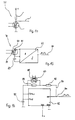
- the one shown in FIG Sensor part 78 is a heatable by means of a heating device 79
- Gas sensor element 80 provided, depending on Gas application of variable ohmic resistance 81 with an oscillating circuit 82 is combined, which as a further, the frequency-determining component has a capacitor 83.
- the oscillation circuit 82 generates an output signal which through line 84 of a downstream evaluation unit is fed.
- the oscillation circuit 82 as electronic standard module in the form of, for example, one Timers 555 provided.
- This timer block is with a the frequency-determining capacitor 85 connected.
- the timer module 82 has a feedback branch 86.
- the feedback branch 85 there is a depending on the gas supply changeable ohmic resistance 87 of a gas sensor element 88 arranged, which a second resistor 89 connected in parallel is.
- a third resistor 90 is provided in series to the arrangement of the parallel Resistors 87 and 89 is in feedback branch 86 .
- the third resistor By connecting the second resistor 89 in parallel to Resistor 87 of the gas sensor element 88 and the series connection the third resistor to the arrangement of the parallel ones Resistors 87 and 89 will be the minimum and maximum frequency even with a dramatic change of resistance 87 of gas sensor element 88 as a result of sudden and strong gas exposure is limited.
- the ratios of the three resistors 87, 89 and 90 are chosen so that both with extreme low impedance even if the resistance 87 is extremely high of the gas sensor element 88 is the group resistance of the resistors 87, 89, 90 always within an easy to calculate The range remains what is directly related to the frequency of the output signal. This ensures that the frequency of the output signal or could never shift the gas sensor signal into a range, the outside of the recording area of the downstream Evaluation unit is.
- Figure 17 shows a circuit arrangement by means of which Basic pollution of the outside air with pollutants, for example in a rural area very different from that in distinguishes an inner city area from impulsive and dynamically occurring peak loads, for example when driving behind a diesel engine Trucks, at a traffic light or at a particularly busy traffic Intersection can occur, can be separated.
- This circuit arrangement is made on the basis of Experience suggests that the basic burden only changes extremely slowly, whereas, for example peak loads generated by varex vehicles change extremely quickly.
- a gas sensor element 91 shown in FIG a constant current source 92 fed.
- the resulting between the constant current source 92 and the gas sensor element 91 tapped gas sensor voltage is by means of a Line 93 led to a divider 94.
- a line 95 branches off from line 93, by means of which the gas sensor signal is fed to an integrator 96, by means of which a comparison signal for an operational amplifier 97 is formed. In the other input of the operational amplifier 97, the gas sensor signal is fed directly. The output signal of the operational amplifier 97 is also routed to divider 94.
- an output line 98 of the divider 94 a Output signal provided, which is due to of changes slowly changing the basic load Signal components of the gas sensor signal depending the time constant of the timing element or integrator 96 are separated from the gas sensor signal.
- the output signal in the output line 98 of the divider 94 is only that any signal component indicating dynamic peak loads of the gas sensor signal included.
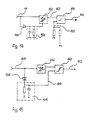
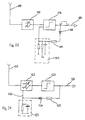
- FIGS. 18 to 21 show further exemplary embodiments shown for circuits by means of which the possibility is to process the gas sensor signal so that the responsiveness the sensor arrangement according to the invention depending on those signal components of the gas sensor signal is regulated, which on the already mentioned several times dynamic peak loads decrease.
- the sensor signal through a line 99 to a diode 100, via which charges the gas sensor signal 99 to an RC element 101; hereby a control voltage is generated that is controllable Amplifier 102 is supplied.
- the level of the output signal on output line 103 of the controllable amplifier 102 is therefore dependent on the state of charge of the RC link 101, which logically depends on the dynamics and the frequency of the gas sensor signal is dependent.
- the Switch amplifier 104 generates in its output line 106 then a switching signal when the regulated gas sensor signal level exceeds the level specified by the trigger level.
- the so-called dynamic gas sensor signal that only those signal components includes the dynamic loads on the gas sensor element due to impulsive load peaks go back through a line 107 of a diode 108 supplied, via which an RC element 109 is charged.
- the so voltage generated by means of the RC element 109 is applied via a Connection line 110 entered a switching amplifier 111, whereby as a switching amplifier 111 a signal-dependent and insofar as variable trigger voltage is present.
- the dynamic gas sensor signal is the switching amplifier 111 fed through an amplifier 112, whereby it the switching amplifier 111 corresponding to the switching threshold, i.e. that is, according to the variable generated by the RC element Trigger voltage, triggers. In an output line 113 of the Switching amplifier 111 then becomes a switching signal available posed.
- FIG. 1 is the dynamic gas sensor signal explained above and has already been mentioned several times by a management 114 via an amplifier 115 a switching amplifier 116 is supplied.
- the switching voltage results from the voltage of a voltage divider with an additional capacitor circuit 117, the voltage of the in an output line 120 of the Switch amplifier 116 present output signal via a Diode 118 and a charging resistor 119 the capacitor circuit 117 influenced, with the tendency that, if in the output line 120 of the switching amplifier 116 frequently an output or switching signal is present, the trigger threshold of Switch amplifier 116 is adjusted so that the circuit arrangement "less sensitive" to changes in the line 114 dynamic gas sensor signal input to it responds.
- the switching amplifier downstream of the controllable amplifier 122 123 works with a fixed switching threshold.
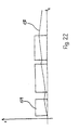
- FIG. 22 shows how output signals 129 of the Switching amplifier, the charging characteristic 130 of the RC element influence. It is clear that the charging voltage is one Function of both the frequency and the switching duration of the output signal of the switching amplifier mentioned above is.
- the evaluation unit can with the circuits described above as the central programmed microprocessor to be designed according to one according to the switching criteria set out above designed digital / numerical model works.
- Sensor arrangement is the actual sensor part with a largely reduced to the necessary Minimal evaluation electronics combined and in one protected housing.
- the actual evaluation of data takes place in many motor vehicles anyway existing microcomputer of a central heating and climate control unit instead.
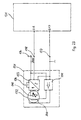
- Circuit arrangement has a sensor module 131, the a gas sensor element 132, an oscillation circuit 133, a the frequency of the oscillation circuit 133 determining capacitor 134 and a heating control 135.
- the gas sensor element 132 has one depending on the gas supply changeable ohmic resistor 140 connected to the oscillation circuit 133 is connected, the frequency of which by Capacitor 134 is determined. By means of the heating system 135 becomes a heater 141 of the gas sensor element 132 regulated.
- the sensor module 131 is connected via electrical lines 136 and 137 to a voltage source, e.g. the central heating and Air conditioning control unit, connected.
- a voltage source e.g. the central heating and Air conditioning control unit
Landscapes
- Engineering & Computer Science (AREA)
- Life Sciences & Earth Sciences (AREA)
- Chemical & Material Sciences (AREA)
- Physics & Mathematics (AREA)
- Mechanical Engineering (AREA)
- Health & Medical Sciences (AREA)
- General Physics & Mathematics (AREA)
- General Health & Medical Sciences (AREA)
- Atmospheric Sciences (AREA)
- Biochemistry (AREA)
- Medicinal Chemistry (AREA)
- Food Science & Technology (AREA)
- Immunology (AREA)
- Pathology (AREA)
- Analytical Chemistry (AREA)
- Environmental & Geological Engineering (AREA)
- Combustion & Propulsion (AREA)
- Thermal Sciences (AREA)
- Automation & Control Theory (AREA)
- Investigating Or Analyzing Materials By The Use Of Fluid Adsorption Or Reactions (AREA)
- Investigating Or Analyzing Materials By The Use Of Electric Means (AREA)
- Ventilation (AREA)
- Air-Conditioning For Vehicles (AREA)
Claims (29)
- Système de capteurs pour la commande d'installations de ventilation dans des véhicules, en mode recirculation d'air ou en mode admission d'air frais, en fonction de la concentration de polluants dans l'air à l'extérieur du véhicule, comprenant un élément capteur de gaz (52), dont la résistance électrique diminue en présence de gaz réducteurs et augmente en présence de gaz oxydants, et une unité de traitement (51), dont la sortie est connectée à la commande de l'installation de ventilation, caractérisé par le fait que le système de capteurs est agencé de telle sorte que la montée d'un signal de capteur de gaz transmis à l'unité de traitement lors d'une élévation de la concentration de gaz réducteurs corresponde sensiblement en valeur à la baisse du signal de capteur de gaz transmis à l'unité de traitement (51) lors d'une élévation correspondante de la concentration de gaz oxydants, que l'unité de traitement (51) détermine à partir du signal de capteur de gaz qui lui est transmis l'élévation ou la baisse de celui-ci par unité de temps et que l'unité de traitement (51) produit un signal de commutation pour amener l'installation de ventilation en mode recirculation de l'air dès que l'élévation ou la baisse déterminée du signal de capteur de gaz par unité de temps dépasse en valeur une valeur seuil.
- Système de capteurs selon la revendication 1, dans lequel, dans l'unité de traitement (51), une valeur moyenne (31) pour une période déterminée est formée à partir du signal de capteur de gaz, une bande (32) définie est associée à ladite valeur moyenne par une majoration et une minoration proportionnelle ou par addition et soustraction d'une valeur absolue, et le signal de commutation est produit lorsque le signal de capteur de gaz se situe en dehors de cette bande (32).
- Système de capteurs selon la revendication 1 ou 2, dans lequel l'unité de traitement (51) présente un filtre passe-bande (57) qui laisse passer exclusivement un spectre d'amplitude indiquant une élévation ou une baisse du signal de capteur de gaz par unité de temps supérieure à la valeur seuil, par lequel le signal de capteur de gaz transite aux fins de déterminer une telle élévation ou baisse de signal du capteur de gaz par unité de temps et dont le signal de sortie est utilisé pour produire les signaux de commutation pour la commande de l'installation de ventilation.
- Système de capteurs selon la revendication 1 ou 2, dans lequel l'unité de traitement (51) comporte un dispositif de calcul pour réaliser une transformation de Fourier, dans lequel le signal de capteur de gaz est examiné par calcul sur la présence d'un spectre d'amplitude donné, indiquant une élévation ou une baisse du signal de capteur de gaz par unité de temps supérieure à la valeur seuil et dans lequel, dans l'unité de traitement (51), le signal de commutation pour la commande de l'installation de ventilation est produit lorsqu'un tel spectre d'amplitude est déterminé dans le signal de capteur de gaz.
- Système de capteurs selon la revendication 1 ou 2, dans lequel l'unité de traitement (51) comporte un réseau électronique neuronal dans lequel le signal de capteur de gaz est examiné au niveau de ses caractéristiques sur la présence d'une élévation ou d'une baisse du signal de capteur de gaz par unité de temps supérieure à la valeur seuil et dans lequel, dans l'unité de traitement (51), le signal de commutation est produit lorsqu'au cours de cet examen une élévation ou une baisse du signal de capteur de gaz par unité de temps supérieure à la valeur seuil est déterminée.
- Système de capteurs selon la revendication 5, dans lequel le réseau électronique neuronal est agencé en réseau neuronal dynamique à trois couches ou multicouches.
- Système de capteurs selon la revendication 5, dans lequel le réseau électronique neuronal est agencé en réseau neuronal bouclé à trois couches ou multicouches.
- Système de capteurs selon la revendication 1 ou 2, dans lequel l'unité de traitement (51) comporte une unité électronique de logique floue à l'aide de laquelle une élévation ou une baisse du signal de capteur de gaz par unité de temps supérieure à la valeur seuil peut être détectée dans le signal de capteur de gaz et dans lequel, dans l'unité de traitement (51), le signal de commutation est produit lorsqu'au cours de cet examen une élévation ou une baisse du signal de capteur de gaz par unité de temps supérieure à la valeur seuil est déterminée.
- Système de capteurs selon une des revendications 1 à 8, dans lequel l'unité de traitement (51) comporte un dispositif de mémoire dans lequel des points d'inversion de pente (40, 45) du signal de capteur de gaz sont mémorisés et dans lequel, côté sortie de l'unité de traitement, le signal de commutation disparaít lorsque le signal de capteur de gaz, après un point d'inversion de pente (40, 45), présente une différence de niveau de signal (42, 48) donnée prédéterminable par rapport au point d'inversion de pente (40, 45) et le signal de capteur de gaz se situe dans la bande (32) associée à la valeur moyenne (31) formée.
- Système de capteurs selon une des revendications 1 à 9, dans lequel l'unité de traitement (51) comporte un dispositif de réglage pour modifier la sensibilité de réaction du système de capteurs à l'aide duquel la sensibilité de réaction du système de capteurs peut être abaissée ou augmentée, lorsque la fréquence des élévations ou des baisses du signal de capteur de gaz par unité de temps supérieures à la valeur seuil augmente voire diminue, la valeur de la modification de la sensibilité de réaction du système de capteurs par unité de temps étant limitée.
- Système de capteurs selon une des revendications 1 à 10, dans lequel l'unité de traitement (51) comporte un dispositif de mesure de temps à l'aide duquel les temps de fonctionnement du dispositif de ventilation en mode admission d'air frais et en mode recirculation d'air peuvent être mesurés, un dispositif de calcul à l'aide duquel le quotient du temps de fonctionnement en mode admission d'air frais et du temps de fonctionnement en mode recirculation d'air peut être calculé et un dispositif de réglage à l'aide duquel la sensibilité de réaction du système de capteurs est diminuée lorsque le fonctionnement en mode recirculation d'air croít et est augmentée lorsque le fonctionnement en mode admission d'air frais croít, la valeur des modifications de la sensibilité de réaction du système de capteurs par unité de temps étant limitée.
- Système de capteurs selon la revendication 10 ou 11, dans lequel le dispositif de réglage pour modifier la sensibilité du système de capteurs comprend un capteur de température extérieure qui mesure la température de l'air à l'extérieur du véhicule, un capteur de température intérieure qui mesure la température de l'air à l'intérieur du véhicule et un dispositif comparateur qui compare la température d'air extérieure fournie par le capteur de température extérieure à la température d'air intérieure fournie par le capteur de température intérieure, le dispositif de réglage augmentant ou diminuant la sensibilité de réaction du système de capteurs lorsque la température d'air extérieure est supérieure ou inférieure à la température d'air intérieure.
- Système de capteurs selon une des revendications 1 à 12, dans lequel l'unité de traitement (51) avec la commande de l'installation de ventilation est agencée sous forme de microprocesseur central programmé.
- Système de capteurs selon une des revendications 1 à 12, dans lequel l'unité de traitement (51) avec la commande de l'installation de ventilation est de type analogique.
- Système de capteurs selon une des revendications 1 à 14, dans lequel l'élément capteur de gaz (52) est agencé sous la forme d'un élément capteur à oxydes mixtes dont la couche sensible contient du dioxyde de zinc (SnO2), du trioxyde de tungstène (WO3), de l'oxyde de fer (Fe2O3), de l'oxyde d'aluminium (Al2O3) et, comme accélérateur de la réaction, du platine (Pt) et du palladium (Pd).
- Système de capteurs selon la revendication 15, dans lequel la couche sensible de l'élément capteur de gaz (52) contient de 29 à 49% de dioxyde de zinc (SnO2), de 7 à 13% d'oxyde de fer (Fe2O3), de 28 à 48% de trioxyde de tungstène (WO3), de 7 à 13% d'oxyde d'aluminium (Al2O3), de 1 à 3% de palladium (Pd) et de 0,5 à 1,5% de platine (Pt).
- Système de capteurs selon une des revendications 1 à 16, dans lequel l'élément capteur de gaz (52) est connecté électriquement à des fils en métal précieux, de préférence à des fils de platine, et est inséré dans un évidement (75) d'une carte à circuit imprimé (66) de l'unité de traitement (51) sensiblement avec le même plan médian que la carte à circuit imprimé (66) et les bornes de l'élément capteur de gaz sont soudées directement sur la cane à circuit imprimé (66), de telle sorte que ledit élément capteur de gaz (52) est suspendu.
- Système de capteurs selon une des revendications 1 à 17, dans lequel l'élément capteur de gaz (52) est disposé dans une chambre (67) qui est fermée de manière étanche au gaz par rapport à l'unité de traitement (51), présente un faible volume et comporte une paroi (68) à forme stable, perméable au gaz.
- Système de capteurs selon la revendication 18, dans lequel la paroi (68) de la chambre (67) est réalisée au moins partiellement en un matériau perforé qui porte avec stabilité de forme au moins une couche d'un matériau perméable au gaz et supporte mécaniquement celui-ci.
- Système de capteurs selon la revendication 18 ou 19, dans lequel la couche (72) au nombre d'au moins une de matériau perméable au gaz est disposée entre deux couches (73, 74) de toile métallique.
- Système de capteurs selon la revendication 18 ou 19, dans lequel la couche (72) au nombre d'au moins une de matériau perméable au gaz est noyée entre deux couches à forme stable, perforées, de matière thermoplastique.
- Système de capteurs selon une des revendications 18 à 21, dans lequel la couche (72) au nombre d'au moins une de matériau perméable au gaz est formée d'un film de matière plastique.
- Système de capteurs selon la revendication 22, dans lequel le film de matière plastique est en téflon ou une matière similaire.
- Système de capteurs selon la revendication 23, dans lequel la paroi (68) à forme stable perméable au gaz de la chambre (67) contenant l'élément capteur de gaz (52) est réalisée en matière plastique frittée, en verre fritté, en métal fritté ou similaire.
- Système de capteurs selon une des revendications 1 à 24, dans lequel l'élément capteur de gaz (132) et une unité élémentaire (133, 134, 135) de l'unité de traitement sont regroupés en un module capteur (131), l'unité élémentaire (133, 134, 135) de l'unité de traitement comporte un circuit oscillant (133), un condensateur (134) pour déterminer la fréquence du circuit oscillant (133) et un dispositif de régulation de chauffage (135) pour réguler la température de l'élément capteur de gaz (132) et le circuit oscillant (133) et le dispositif de régulation de température (135) sont connectés à appareil central de commande de chauffage et de climatisation (139) du véhicule, le traitement d'un signal de sortie du module capteur (131) ayant lieu de manière entièrement numérique dans le microcalculateur de l'appareil central de commande de chauffage et de climatisation (139).
- Système de capteurs selon une des revendications 1 à 25, dans lequel l'élément capteur de gaz (132) en oxyde métallique est maintenu à une température constante au moyen d'un dispositif de chauffage (53).
- Système de capteurs selon une des revendications 1 à 26, dans lequel la résistance ohmique (140) de l'élément capteur de gaz (132) fait partie d'un circuit oscillant (133) et est parcourue par une tension alternative à fréquence moyenne.
- Système de capteurs selon la revendication 27, dans lequel il est prévu un condensateur (134) qui produit la fréquence du circuit oscillant (133).
- Système de capteurs selon une des revendications 26 à 28, dans lequel le circuit oscillant (82) comporte un composant rythmeur (82) qui est connecté à un condensateur (85) déterminant la fréquence et présente une branche de rétroaction (85) dans laquelle sont insérées la résistance (87) de l'élément capteur de gaz (88) et une deuxième résistance (90) et qui présente une branche en parallèle avec la résistance (87) de l'élément capteur de gaz (88) dans laquelle est placée une troisième résistance (89).
Applications Claiming Priority (5)
| Application Number | Priority Date | Filing Date | Title |
|---|---|---|---|
| DE4414594 | 1994-04-27 | ||
| DE4414594A DE4414594A1 (de) | 1994-04-27 | 1994-04-27 | Sensor zum Zwecke der schadstoffabhängigen Lüftungssteuerung, insbesondere zur Kfz.-Belüftung |
| DE4436938A DE4436938A1 (de) | 1994-04-27 | 1994-10-15 | Nässe- und windgeschützter Gassensor |
| DE4436938 | 1994-10-15 | ||
| PCT/EP1994/004338 WO1995029072A1 (fr) | 1994-04-27 | 1994-12-29 | Dispositif a detecteur pour la commande de systemes de ventilation dans des vehicules |
Publications (2)
| Publication Number | Publication Date |
|---|---|
| EP0757632A1 EP0757632A1 (fr) | 1997-02-12 |
| EP0757632B1 true EP0757632B1 (fr) | 2000-03-22 |
Family
ID=25935965
Family Applications (1)
| Application Number | Title | Priority Date | Filing Date |
|---|---|---|---|
| EP95905112A Expired - Lifetime EP0757632B1 (fr) | 1994-04-27 | 1994-12-29 | Dispositif a detecteur pour la commande de systemes de ventilation dans des vehicules |
Country Status (18)
| Country | Link |
|---|---|
| US (1) | US5725425A (fr) |
| EP (1) | EP0757632B1 (fr) |
| JP (1) | JP3024217B2 (fr) |
| KR (1) | KR100330975B1 (fr) |
| CN (1) | CN1154901C (fr) |
| AT (1) | ATE190920T1 (fr) |
| AU (1) | AU687538B2 (fr) |
| BR (1) | BR9506808A (fr) |
| CA (1) | CA2188925C (fr) |
| DE (2) | DE4436938A1 (fr) |
| ES (1) | ES2146308T3 (fr) |
| IL (1) | IL113064A (fr) |
| PH (1) | PH31368A (fr) |
| PT (1) | PT757632E (fr) |
| RU (1) | RU2236035C2 (fr) |
| TR (1) | TR28916A (fr) |
| TW (1) | TW332801B (fr) |
| WO (2) | WO1995029072A1 (fr) |
Cited By (1)
| Publication number | Priority date | Publication date | Assignee | Title |
|---|---|---|---|---|
| DE102005006312B4 (de) | 2005-02-11 | 2022-10-20 | Bayerische Motoren Werke Aktiengesellschaft | Verfahren zur Ansteuerung einer Lüftungs- und/oder Klimatisierungseinheit |
Families Citing this family (51)
| Publication number | Priority date | Publication date | Assignee | Title |
|---|---|---|---|---|
| DE19543296C2 (de) * | 1995-11-21 | 2001-02-22 | I T V I Internat Techno Ventur | Verfahren zur Ermittlung absoluter Gaskonzentrationen unter Verwendung halbleitender Gassensoren |
| DE19619553B4 (de) * | 1996-05-15 | 2008-07-17 | Paragon Ag | Schaltungsanordnung und Verfahren zur schadstoffgesteuerten Belüftung einer Fahrzeugkabine |
| DE19637232A1 (de) * | 1996-09-13 | 1998-03-19 | Behr Gmbh & Co | Vorrichtung und Verfahren zur Steuerung von Luftführungselementen eines Fahrzeugs |
| WO1998049547A1 (fr) * | 1997-04-30 | 1998-11-05 | T/J Technologies, Inc. | Detecteurs chimiques et leurs procedes d'utilisation |
| DE19720293C1 (de) * | 1997-05-15 | 1998-06-04 | Daimler Benz Ag | Vorrichtung und Verfahren zur schadgasabhängigen Fahrzeuginnenraumbelüftung |
| US5996337A (en) * | 1998-02-06 | 1999-12-07 | Engelhard Corporation | Dynamic calorimetric sensor system |
| DE19811069C2 (de) * | 1998-03-13 | 2000-03-09 | Siemens Ag | Meßschaltung zur Ermittlung der Konzentration eines oder mehrerer Gase in einem Gasgemisch |
| JP3693819B2 (ja) * | 1998-07-07 | 2005-09-14 | カルソニックカンセイ株式会社 | インテークドア制御装置 |
| FR2785855B1 (fr) | 1998-11-18 | 2001-03-30 | Valeo Climatisation | Dispositif de chauffage et/ou climatisation de vehicule automobile comprenant un capteur de pollution |
| KR100357219B1 (ko) * | 1999-04-14 | 2002-10-18 | 오토전자 주식회사 | 배기가스 센서 및 배기가스 센서를 이용한 환기 제어 장치 |
| US6314793B1 (en) * | 1999-09-28 | 2001-11-13 | Gas Research Institute | Test device for measuring chemical emissions |
| DE10101755C1 (de) * | 2001-01-16 | 2002-07-11 | Siemens Ag | Vorrichtung zur Bestimmung des Innenwiderstandes einer Linearen Sauerstoffsonde |
| KR100394767B1 (ko) * | 2001-02-07 | 2003-08-19 | 김이곤 | 대기오염자동감시체제의 지능형 상태판정방법 및 그의 시스템 |
| DE10114524B4 (de) * | 2001-03-21 | 2004-02-19 | Bombardier Transportation Gmbh | Verfahren und Anordnung zur Klimatisierung schnellfahrender Fahrzeuge |
| US6768423B2 (en) * | 2002-02-21 | 2004-07-27 | Case Corporation | Cab environment warning and control method and apparatus |
| US6800022B2 (en) * | 2003-02-19 | 2004-10-05 | Delphi Technologies, Inc. | Inlet air control method for a vehicle HVAC system having an air quality sensor |
| JP4074634B2 (ja) * | 2003-09-09 | 2008-04-09 | エフアイエス株式会社 | ガス検出装置 |
| DE102004013678A1 (de) | 2004-03-18 | 2005-10-20 | Micronas Gmbh | Vorrichtung zur Detektion eines Gases oder Gasgemischs |
| US7803039B2 (en) * | 2004-06-18 | 2010-09-28 | Denso Corporation | Method of controlling air intake into air conditioned enclosure |
| KR100698906B1 (ko) * | 2004-08-10 | 2007-03-22 | 삼성전자주식회사 | 환기 시스템의 제어장치 및 그 방법 |
| WO2006016346A1 (fr) * | 2004-08-11 | 2006-02-16 | Koninklijke Philips Electronics N.V. | Systeme de detection de pollution atmospherique |
| RU2309451C2 (ru) * | 2005-04-19 | 2007-10-27 | Государственное образовательное учреждение высшего профессионального образования Московский государственный институт электроники и математики (технический университет) | Способ управления компьютерной сетью и система для его осуществления |
| KR100764862B1 (ko) * | 2006-03-07 | 2007-10-09 | 에후 아이 에스 가부시키가이샤 | 가스 검출 장치 |
| US8092285B2 (en) * | 2006-03-21 | 2012-01-10 | Calsonickansei North America, Inc. | System and method for controlling a ventilation unit of a vehicle |
| US8257286B2 (en) * | 2006-09-21 | 2012-09-04 | Tyco Healthcare Group Lp | Safety connector apparatus |
| JP5519294B2 (ja) * | 2007-01-10 | 2014-06-11 | コーニンクレッカ フィリップス エヌ ヴェ | 空調システムを制御するための制御システム |
| US8257287B2 (en) | 2008-03-20 | 2012-09-04 | Tyco Healthcare Group Lp | Safety connector assembly |
| KR101024392B1 (ko) * | 2008-05-23 | 2011-03-23 | 주식회사 오토산업 | 차량내 환경제어 시스템 |
| DE102008042518A1 (de) * | 2008-10-01 | 2010-04-08 | Robert Bosch Gmbh | Verfahren zur Auswahl von zu ergreifenden Sicherheitsmaßnahmen zur Erhöhung einer Sicherheit von Fahrzeuginsassen |
| KR101169231B1 (ko) * | 2009-06-30 | 2012-08-02 | 주식회사 과학기술분석센타 | 방지시설 관리방법 및 방지시설 관리 시스템 |
| DE102010018499A1 (de) * | 2010-04-22 | 2011-10-27 | Schweizer Electronic Ag | Leiterplatte mit Hohlraum |
| US10639961B2 (en) * | 2010-07-07 | 2020-05-05 | Ford Global Technologies, Llc | Partial air inlet control strategy for air conditioning system |
| KR20130114769A (ko) * | 2012-04-10 | 2013-10-21 | 현대자동차주식회사 | 차량의 배기가스 유입 방지 방법 및 시스템 |
| WO2015021538A1 (fr) * | 2013-08-16 | 2015-02-19 | Kevin Allan Dooley Inc. | Systèmes et procédés de commande de pressions à infrasons |
| US20160023770A1 (en) * | 2014-07-25 | 2016-01-28 | Nathan Thompson | Air heating apparatus useful for heating an aircraft interior |
| US9957052B2 (en) | 2015-01-27 | 2018-05-01 | Honeywell International Inc. | Aircraft environmental control system that optimizes the proportion of outside air from engines, APU's, ground air sources and the recirculated cabin air to maintain occupant comfort and maximize fuel economy |
| US9776725B2 (en) | 2015-01-27 | 2017-10-03 | Honeywell International Inc. | Human factors approach to control contaminant concentrations in aircraft supply air from engine and APU bleed air and ground air sources, and in recirculated air being delivered to aircraft cabins for the optimization of user experience and energy consumption |
| US9688194B2 (en) * | 2015-03-26 | 2017-06-27 | Ford Global Technologies, Llc | In-vehicle particulate sensor data analysis |
| RU2585520C1 (ru) * | 2015-04-14 | 2016-05-27 | Общество с ограниченной ответственностью "АВТЭКС" | Система вентиляции транспортного средства с избирательным удалением продуктов выдоха |
| CN105068585A (zh) * | 2015-08-04 | 2015-11-18 | 吴天钢 | 一种户外配网设备微环境控制系统 |
| US9884281B2 (en) | 2015-09-18 | 2018-02-06 | Honeywell International Inc. | Method to use ultrafine particulate matter detection and measurement to control air supply system contaminant delivery to the aircraft cabin environment |
| US10112618B2 (en) | 2015-10-11 | 2018-10-30 | Rimalu Technologies, Inc. | Traffic pollution indicator |
| RU2624124C1 (ru) * | 2016-03-14 | 2017-06-30 | Олег Савельевич Кочетов | Мобильная система обучения населения действиям в условиях чрезвычайных ситуаций |
| US10887722B2 (en) | 2016-03-16 | 2021-01-05 | Airlib Inc. | Traffic pollution mapper |
| US10195921B2 (en) * | 2016-06-21 | 2019-02-05 | Nissan North America, Inc. | Vehicle air conditioning system |
| US10427797B2 (en) * | 2017-01-20 | 2019-10-01 | Honeywell International Inc. | Systems and methods for reducing environmental control system maintenance |
| KR20180112533A (ko) * | 2017-04-04 | 2018-10-12 | 현대자동차주식회사 | 차량의 실내 공기질 개선 장치 |
| DE102018202395A1 (de) * | 2018-02-16 | 2019-08-22 | Robert Bosch Gmbh | Gassensor, Elektrogerät, Vorrichtung und/oder Fahrzeug und Verfahren zum Betreiben eines Fahrzeuges |
| CN110395286B (zh) * | 2019-08-02 | 2020-08-07 | 中南大学 | 一种列车车内空气品质监测与通风调控方法、系统 |
| CN114729873B (zh) | 2019-11-14 | 2025-10-10 | 金泰克斯公司 | 用于化学检测和放大的系统和方法 |
| KR20240084566A (ko) | 2022-12-06 | 2024-06-13 | 전주비전대학교산학협력단 | 센서 기반 차량 자동 환기 시스템 |
Family Cites Families (10)
| Publication number | Priority date | Publication date | Assignee | Title |
|---|---|---|---|---|
| US4292965A (en) * | 1978-12-29 | 1981-10-06 | The Population Council, Inc. | Intravaginal ring |
| JPS5943327B2 (ja) * | 1980-12-02 | 1984-10-22 | 株式会社デンソー | 車両用空調制御装置 |
| EP0308455B1 (fr) * | 1987-04-02 | 1993-01-27 | Eftag Entstaubungs- Und Fördertechnik Ag | Circuit d'evaluation de signaux generes par des capteurs de gaz a semiconducteurs |
| JP2741381B2 (ja) * | 1988-02-04 | 1998-04-15 | フィガロ技研株式会社 | ガス検出装置 |
| DE3825036A1 (de) * | 1988-07-23 | 1990-01-25 | E T R Gmbh | Vorrichtung zur durchfuehrung des verfahrens der sensorgesteuerten umluftklappen von fahrzeugkabinen |
| RU2005281C1 (ru) * | 1991-01-14 | 1993-12-30 | Государственный проектный, конструкторский научно-исследовательский институт "СантехНИИпроект" | Способ регулировани температуры смеси наружного и рециркул ционного воздуха на выходе теплообменника и система автоматического управлени приточной вентил ционной установкой |
| DE4106078A1 (de) * | 1991-02-27 | 1992-09-03 | Daimler Benz Ag | Vorrichtung bzw. verfahren zur steuerung der belueftung eines innenraumes, insbesondere bei kraftfahrzeugen |
| US5252949A (en) * | 1991-08-28 | 1993-10-12 | Hughes Aircraft Company | Chemical sensor for carbon monoxide detection |
| GB2266365A (en) * | 1992-04-22 | 1993-10-27 | Norm Pacific Automat Corp | Air conditioning |
| US5320577A (en) * | 1993-03-22 | 1994-06-14 | Figaro Engineering Inc. | Air conditioner control device |
-
1994
- 1994-10-15 DE DE4436938A patent/DE4436938A1/de not_active Ceased
- 1994-12-29 WO PCT/EP1994/004338 patent/WO1995029072A1/fr not_active Ceased
- 1994-12-29 AT AT95905112T patent/ATE190920T1/de not_active IP Right Cessation
- 1994-12-29 DE DE59409246T patent/DE59409246D1/de not_active Expired - Lifetime
- 1994-12-29 EP EP95905112A patent/EP0757632B1/fr not_active Expired - Lifetime
- 1994-12-29 ES ES95905112T patent/ES2146308T3/es not_active Expired - Lifetime
- 1994-12-29 PT PT95905112T patent/PT757632E/pt unknown
-
1995
- 1995-03-21 IL IL11306495A patent/IL113064A/xx not_active IP Right Cessation
- 1995-03-24 PH PH50180A patent/PH31368A/en unknown
- 1995-03-31 TW TW084103111A patent/TW332801B/zh not_active IP Right Cessation
- 1995-04-06 RU RU96122786/09A patent/RU2236035C2/ru active
- 1995-04-06 US US08/700,398 patent/US5725425A/en not_active Expired - Lifetime
- 1995-04-06 AU AU21492/95A patent/AU687538B2/en not_active Expired
- 1995-04-06 WO PCT/KR1995/000033 patent/WO1995029435A1/fr not_active Ceased
- 1995-04-06 BR BR9506808A patent/BR9506808A/pt not_active IP Right Cessation
- 1995-04-06 KR KR1019960703718A patent/KR100330975B1/ko not_active Expired - Lifetime
- 1995-04-06 JP JP7527543A patent/JP3024217B2/ja not_active Expired - Fee Related
- 1995-04-06 CN CNB951920065A patent/CN1154901C/zh not_active Expired - Lifetime
- 1995-04-06 CA CA002188925A patent/CA2188925C/fr not_active Expired - Lifetime
- 1995-04-27 TR TR00487/95A patent/TR28916A/xx unknown
Cited By (1)
| Publication number | Priority date | Publication date | Assignee | Title |
|---|---|---|---|---|
| DE102005006312B4 (de) | 2005-02-11 | 2022-10-20 | Bayerische Motoren Werke Aktiengesellschaft | Verfahren zur Ansteuerung einer Lüftungs- und/oder Klimatisierungseinheit |
Also Published As
| Publication number | Publication date |
|---|---|
| RU2236035C2 (ru) | 2004-09-10 |
| ATE190920T1 (de) | 2000-04-15 |
| JPH09512509A (ja) | 1997-12-16 |
| CN1154901C (zh) | 2004-06-23 |
| JP3024217B2 (ja) | 2000-03-21 |
| WO1995029435A1 (fr) | 1995-11-02 |
| TW332801B (en) | 1998-06-01 |
| CN1143420A (zh) | 1997-02-19 |
| PT757632E (pt) | 2000-09-29 |
| CA2188925C (fr) | 2003-07-08 |
| WO1995029072A1 (fr) | 1995-11-02 |
| DE4436938A1 (de) | 1996-04-18 |
| ES2146308T3 (es) | 2000-08-01 |
| PH31368A (en) | 1998-08-12 |
| BR9506808A (pt) | 1997-10-14 |
| EP0757632A1 (fr) | 1997-02-12 |
| KR970700331A (ko) | 1997-01-08 |
| KR100330975B1 (ko) | 2002-10-04 |
| TR28916A (tr) | 1997-08-04 |
| US5725425A (en) | 1998-03-10 |
| IL113064A0 (en) | 1995-06-29 |
| CA2188925A1 (fr) | 1995-11-02 |
| DE59409246D1 (de) | 2000-04-27 |
| AU687538B2 (en) | 1998-02-26 |
| AU2149295A (en) | 1995-11-16 |
| IL113064A (en) | 1999-11-30 |
Similar Documents
| Publication | Publication Date | Title |
|---|---|---|
| EP0757632B1 (fr) | Dispositif a detecteur pour la commande de systemes de ventilation dans des vehicules | |
| EP0231231B1 (fr) | Procede de detection de substances toxiques dans l'air introduit dans une cabine ou enceinte similaire de sejour de personnes | |
| DE69224105T2 (de) | Klimaanlage | |
| EP3312031A1 (fr) | Système d'aération dans un dispositif mobile et procédé de fonctionnement d'un système d'aération dans un dispositif mobile | |
| DE69736795T2 (de) | Verfahren zur Steuerung des Abgassystems einer Brennkraftmaschine | |
| DE19720293C1 (de) | Vorrichtung und Verfahren zur schadgasabhängigen Fahrzeuginnenraumbelüftung | |
| EP2880368B1 (fr) | Hotte aspirante et procédé d'activation d'un moteur de ventilateur | |
| EP0357882A2 (fr) | Dispositif pour alimenter le tuyau d'admission d'un moteur à combustion interne en quantités dosées de composants volatils de carburants | |
| EP0287599B1 (fr) | Capteur pour commander des clapets de circulation d'air sur des vehicules a moteurs | |
| DE102014010712A1 (de) | "Gassensoranordnung zur Messung einer Zielgaskonzentration" | |
| DE6935845U (de) | Infrarot-analysator und verfahren zur eichung eines solchen analysators | |
| DE3807907A1 (de) | Sauerstoffuehler, und lambdaregelung fuer eine brennkraftmaschine mit einem solchen fuehler | |
| DE102014010713A1 (de) | "Gassensoranordnung zur Messung einer Zielgaskonzentration" | |
| DE3609227C2 (fr) | ||
| DE2408218C3 (de) | Schaltungsanordnung zum Nachweis von Gasen | |
| DE3835672A1 (de) | Verfahren und vorrichtung zur ueberwachung des verschmutzungsgrades von filtern | |
| EP0713454B1 (fr) | Evaluation de signaux de capteurs polluants | |
| DE4414594A1 (de) | Sensor zum Zwecke der schadstoffabhängigen Lüftungssteuerung, insbesondere zur Kfz.-Belüftung | |
| DE10142711B4 (de) | Vorrichtung mit einer Sensoranordnung zur Bestimmung der Umgebungsluftgüte sowie einer Anordnung von Ozonsensoren vor und hinter einem mit einem Katalysatormaterial beschichteten Kühler und Verfahren | |
| DE102021132344B4 (de) | Verfahren zum Schalten einer Lüftungseinheit und eine entsprechende Lüftungseinheit | |
| DE2254465A1 (de) | Messeinrichtung fuer das mischungsverhaeltnis des luft-kraftstoff-gemisches bei verbrennungsmaschinen, insbesondere bei verbrennungsmotoren von kraftfahrzeugen | |
| DE3731745A1 (de) | Vorrichtung und verfahren zur signalauswertung von gassensoren zum zwecke der klimasteuerung in kraftfahrzeugen | |
| DE4105598A1 (de) | Messeinrichtung zur erfassung von gasen mit einem sensor und einem gasfilter | |
| DE10254852A1 (de) | Schaltungsanordnung zur Sensorauswertung und Verfahren zur Auswertung mehrerer Sensoren | |
| DE202005002221U1 (de) | Ansteuerung einer Fahrzeug-Lüftungseinheit mit Bewertung der Außenraum- und der Innenraumluft |
Legal Events
| Date | Code | Title | Description |
|---|---|---|---|
| PUAI | Public reference made under article 153(3) epc to a published international application that has entered the european phase |
Free format text: ORIGINAL CODE: 0009012 |
|
| 17P | Request for examination filed |
Effective date: 19961108 |
|
| AK | Designated contracting states |
Kind code of ref document: A1 Designated state(s): AT BE DE ES FR GB IE IT LU NL PT SE |
|
| 17Q | First examination report despatched |
Effective date: 19971117 |
|
| GRAG | Despatch of communication of intention to grant |
Free format text: ORIGINAL CODE: EPIDOS AGRA |
|
| GRAG | Despatch of communication of intention to grant |
Free format text: ORIGINAL CODE: EPIDOS AGRA |
|
| GRAH | Despatch of communication of intention to grant a patent |
Free format text: ORIGINAL CODE: EPIDOS IGRA |
|
| GRAH | Despatch of communication of intention to grant a patent |
Free format text: ORIGINAL CODE: EPIDOS IGRA |
|
| GRAA | (expected) grant |
Free format text: ORIGINAL CODE: 0009210 |
|
| AK | Designated contracting states |
Kind code of ref document: B1 Designated state(s): AT BE DE ES FR GB IE IT LU NL PT SE |
|
| REF | Corresponds to: |
Ref document number: 190920 Country of ref document: AT Date of ref document: 20000415 Kind code of ref document: T |
|
| REF | Corresponds to: |
Ref document number: 59409246 Country of ref document: DE Date of ref document: 20000427 |
|
| REG | Reference to a national code |
Ref country code: IE Ref legal event code: FG4D Free format text: GERMAN |
|
| ITF | It: translation for a ep patent filed | ||
| GBT | Gb: translation of ep patent filed (gb section 77(6)(a)/1977) |
Effective date: 20000623 |
|
| ET | Fr: translation filed | ||
| REG | Reference to a national code |
Ref country code: ES Ref legal event code: FG2A Ref document number: 2146308 Country of ref document: ES Kind code of ref document: T3 |
|
| REG | Reference to a national code |
Ref country code: PT Ref legal event code: SC4A Free format text: AVAILABILITY OF NATIONAL TRANSLATION Effective date: 20000621 |
|
| PLBE | No opposition filed within time limit |
Free format text: ORIGINAL CODE: 0009261 |
|
| STAA | Information on the status of an ep patent application or granted ep patent |
Free format text: STATUS: NO OPPOSITION FILED WITHIN TIME LIMIT |
|
| 26N | No opposition filed | ||
| PGFP | Annual fee paid to national office [announced via postgrant information from national office to epo] |
Ref country code: PT Payment date: 20011204 Year of fee payment: 8 |
|
| PGFP | Annual fee paid to national office [announced via postgrant information from national office to epo] |
Ref country code: AT Payment date: 20011212 Year of fee payment: 8 |
|
| PGFP | Annual fee paid to national office [announced via postgrant information from national office to epo] |
Ref country code: IE Payment date: 20011214 Year of fee payment: 8 |
|
| PGFP | Annual fee paid to national office [announced via postgrant information from national office to epo] |
Ref country code: NL Payment date: 20011221 Year of fee payment: 8 Ref country code: BE Payment date: 20011221 Year of fee payment: 8 |
|
| PGFP | Annual fee paid to national office [announced via postgrant information from national office to epo] |
Ref country code: LU Payment date: 20011227 Year of fee payment: 8 |
|
| REG | Reference to a national code |
Ref country code: GB Ref legal event code: IF02 |
|
| REG | Reference to a national code |
Ref country code: GB Ref legal event code: 732E |
|
| REG | Reference to a national code |
Ref country code: PT Ref legal event code: PC4A Free format text: PARAGON AG DE Effective date: 20020710 |
|
| PG25 | Lapsed in a contracting state [announced via postgrant information from national office to epo] |
Ref country code: LU Free format text: LAPSE BECAUSE OF NON-PAYMENT OF DUE FEES Effective date: 20021229 Ref country code: AT Free format text: LAPSE BECAUSE OF NON-PAYMENT OF DUE FEES Effective date: 20021229 |
|
| PG25 | Lapsed in a contracting state [announced via postgrant information from national office to epo] |
Ref country code: IE Free format text: LAPSE BECAUSE OF NON-PAYMENT OF DUE FEES Effective date: 20021230 |
|
| PG25 | Lapsed in a contracting state [announced via postgrant information from national office to epo] |
Ref country code: BE Free format text: LAPSE BECAUSE OF NON-PAYMENT OF DUE FEES Effective date: 20021231 |
|
| BERE | Be: lapsed |
Owner name: *PARAGON A.G. Effective date: 20021231 |
|
| PG25 | Lapsed in a contracting state [announced via postgrant information from national office to epo] |
Ref country code: PT Free format text: LAPSE BECAUSE OF NON-PAYMENT OF DUE FEES Effective date: 20030630 |
|
| PG25 | Lapsed in a contracting state [announced via postgrant information from national office to epo] |
Ref country code: NL Free format text: LAPSE BECAUSE OF NON-PAYMENT OF DUE FEES Effective date: 20030701 |
|
| NLV4 | Nl: lapsed or anulled due to non-payment of the annual fee |
Effective date: 20030701 |
|
| REG | Reference to a national code |
Ref country code: PT Ref legal event code: MM4A Free format text: LAPSE DUE TO NON-PAYMENT OF FEES Effective date: 20030630 |
|
| REG | Reference to a national code |
Ref country code: IE Ref legal event code: MM4A |
|
| PGFP | Annual fee paid to national office [announced via postgrant information from national office to epo] |
Ref country code: SE Payment date: 20031204 Year of fee payment: 10 |
|
| PGFP | Annual fee paid to national office [announced via postgrant information from national office to epo] |
Ref country code: ES Payment date: 20031210 Year of fee payment: 10 |
|
| PG25 | Lapsed in a contracting state [announced via postgrant information from national office to epo] |
Ref country code: SE Free format text: LAPSE BECAUSE OF NON-PAYMENT OF DUE FEES Effective date: 20041230 Ref country code: ES Free format text: LAPSE BECAUSE OF NON-PAYMENT OF DUE FEES Effective date: 20041230 |
|
| EUG | Se: european patent has lapsed | ||
| REG | Reference to a national code |
Ref country code: ES Ref legal event code: FD2A Effective date: 20041230 |
|
| PGFP | Annual fee paid to national office [announced via postgrant information from national office to epo] |
Ref country code: FR Payment date: 20061215 Year of fee payment: 13 |
|
| PGFP | Annual fee paid to national office [announced via postgrant information from national office to epo] |
Ref country code: GB Payment date: 20061218 Year of fee payment: 13 |
|
| PGFP | Annual fee paid to national office [announced via postgrant information from national office to epo] |
Ref country code: IT Payment date: 20061231 Year of fee payment: 13 |
|
| GBPC | Gb: european patent ceased through non-payment of renewal fee |
Effective date: 20071229 |
|
| REG | Reference to a national code |
Ref country code: FR Ref legal event code: ST Effective date: 20081020 |
|
| PG25 | Lapsed in a contracting state [announced via postgrant information from national office to epo] |
Ref country code: GB Free format text: LAPSE BECAUSE OF NON-PAYMENT OF DUE FEES Effective date: 20071229 |
|
| PG25 | Lapsed in a contracting state [announced via postgrant information from national office to epo] |
Ref country code: FR Free format text: LAPSE BECAUSE OF NON-PAYMENT OF DUE FEES Effective date: 20071231 |
|
| PG25 | Lapsed in a contracting state [announced via postgrant information from national office to epo] |
Ref country code: IT Free format text: LAPSE BECAUSE OF NON-PAYMENT OF DUE FEES Effective date: 20071229 |
|
| PGFP | Annual fee paid to national office [announced via postgrant information from national office to epo] |
Ref country code: DE Payment date: 20130215 Year of fee payment: 19 |
|
| REG | Reference to a national code |
Ref country code: DE Ref legal event code: R119 Ref document number: 59409246 Country of ref document: DE |
|
| REG | Reference to a national code |
Ref country code: DE Ref legal event code: R119 Ref document number: 59409246 Country of ref document: DE Effective date: 20140701 |
|
| PG25 | Lapsed in a contracting state [announced via postgrant information from national office to epo] |
Ref country code: DE Free format text: LAPSE BECAUSE OF NON-PAYMENT OF DUE FEES Effective date: 20140701 |