EP0758055A1 - Dispositif et procédé pour commander électroniquement le débit d'entrée et empêcher le reflux dans un compresseur - Google Patents
Dispositif et procédé pour commander électroniquement le débit d'entrée et empêcher le reflux dans un compresseur Download PDFInfo
- Publication number
- EP0758055A1 EP0758055A1 EP96305787A EP96305787A EP0758055A1 EP 0758055 A1 EP0758055 A1 EP 0758055A1 EP 96305787 A EP96305787 A EP 96305787A EP 96305787 A EP96305787 A EP 96305787A EP 0758055 A1 EP0758055 A1 EP 0758055A1
- Authority
- EP
- European Patent Office
- Prior art keywords
- compressor
- valve member
- inlet
- housing
- actuator
- Prior art date
- Legal status (The legal status is an assumption and is not a legal conclusion. Google has not performed a legal analysis and makes no representation as to the accuracy of the status listed.)
- Granted
Links
- 238000000034 method Methods 0.000 title claims description 13
- 239000012530 fluid Substances 0.000 claims abstract description 10
- 238000006073 displacement reaction Methods 0.000 claims description 3
- 230000003247 decreasing effect Effects 0.000 claims description 2
- 230000033228 biological regulation Effects 0.000 description 3
- 238000012423 maintenance Methods 0.000 description 3
- 238000002347 injection Methods 0.000 description 2
- 239000007924 injection Substances 0.000 description 2
- 230000000903 blocking effect Effects 0.000 description 1
- 238000011109 contamination Methods 0.000 description 1
- 230000007423 decrease Effects 0.000 description 1
- 238000010586 diagram Methods 0.000 description 1
- 230000000694 effects Effects 0.000 description 1
- 230000008014 freezing Effects 0.000 description 1
- 238000007710 freezing Methods 0.000 description 1
Images




Classifications
-
- F—MECHANICAL ENGINEERING; LIGHTING; HEATING; WEAPONS; BLASTING
- F04—POSITIVE - DISPLACEMENT MACHINES FOR LIQUIDS; PUMPS FOR LIQUIDS OR ELASTIC FLUIDS
- F04C—ROTARY-PISTON, OR OSCILLATING-PISTON, POSITIVE-DISPLACEMENT MACHINES FOR LIQUIDS; ROTARY-PISTON, OR OSCILLATING-PISTON, POSITIVE-DISPLACEMENT PUMPS
- F04C28/00—Control of, monitoring of, or safety arrangements for, pumps or pumping installations specially adapted for elastic fluids
- F04C28/24—Control of, monitoring of, or safety arrangements for, pumps or pumping installations specially adapted for elastic fluids characterised by using valves controlling pressure or flow rate, e.g. discharge valves or unloading valves
-
- F—MECHANICAL ENGINEERING; LIGHTING; HEATING; WEAPONS; BLASTING
- F04—POSITIVE - DISPLACEMENT MACHINES FOR LIQUIDS; PUMPS FOR LIQUIDS OR ELASTIC FLUIDS
- F04B—POSITIVE-DISPLACEMENT MACHINES FOR LIQUIDS; PUMPS
- F04B49/00—Control, e.g. of pump delivery, or pump pressure of, or safety measures for, machines, pumps, or pumping installations, not otherwise provided for, or of interest apart from, groups F04B1/00 - F04B47/00
- F04B49/02—Stopping, starting, unloading or idling control
- F04B49/03—Stopping, starting, unloading or idling control by means of valves
-
- F—MECHANICAL ENGINEERING; LIGHTING; HEATING; WEAPONS; BLASTING
- F04—POSITIVE - DISPLACEMENT MACHINES FOR LIQUIDS; PUMPS FOR LIQUIDS OR ELASTIC FLUIDS
- F04C—ROTARY-PISTON, OR OSCILLATING-PISTON, POSITIVE-DISPLACEMENT MACHINES FOR LIQUIDS; ROTARY-PISTON, OR OSCILLATING-PISTON, POSITIVE-DISPLACEMENT PUMPS
- F04C2270/00—Control; Monitoring or safety arrangements
- F04C2270/70—Safety, emergency conditions or requirements
- F04C2270/72—Safety, emergency conditions or requirements preventing reverse rotation
Definitions
- This invention generally relates to a compressor inlet valve, and more particularly to a compressor inlet valve for electronically controlling inlet gas flow and preventing backflow through the compressor inlet.
- a compressor In order to control the throughput or capacity of a compressor, a compressor typically includes an inlet valve which regulates the compressor capacity.
- inlet valve One type of inlet valve is commonly referred to as an unloader valve because the valve is used to load and unload the compressor.
- the compressor is loaded when the inlet valve is open permitting fluid, such as air, to flow through the compressor inlet.
- the compressor is unloaded when the valve is closed thereby "choking" or blocking the flow of fluid through the compressor inlet.
- Unloader valves may be opened and closed pneumatically.
- Pneumatically controlled unloader valves require a regulation air system for operation.
- the pneumatically controlled unloader valves have operated with varying degrees of success, there are problems associated with such valves.
- the regulation air system may freeze and render the inlet valve inoperable.
- the regulation air system requires regular maintenance in order to ensure that the air system can effectively actuate the unloader valve during compressor operation. This regularly conducted maintenance can be time consuming and may render the compressor inoperable when it is being performed.
- Unloader valves may also be opened and closed hydraulically. Hydraulic unloader valves frequently leak hydraulic fluid and require replacement of parts, such as diaphragms, for example.
- Such backflow is comprised of a combination of a gas, such as air, and oil.
- Backflow occurs when the compressor is stopped while the compressor system is pressurized. It is undesirable to permit backflow to be released into the environment because of the loss of oil from the system and associated contamination of the environment.
- One conventional way of preventing backflow is by inserting check valves in the air service and oil injection lines.
- Conventional check valves are spring actuated to permit unidirectional flow of compressed gas or oil, away from the compressor. In this way, backflow is prevented by the check valves.
- current check valves are effective in preventing backflow, it would be more desirable to prevent backflow without introducing additional discrete valves into the system.
- Electronically operated inlet valves typically include a stepper motor that is connected to a disc or piston that is movable by the motor.
- a pressure sensor measures compressor discharge pressure, generates a signal in response to the measured pressure and communicates the signal to a controller.
- the controller calculates the distance that the disc or piston needs to be moved to obtain the desired discharge pressure and rotates the stepper motor in short, discrete angular movements to thereby move the disc or piston the calculated distance.
- the disc or piston when fully closed, does not seal the inlet well enough to prevent backflow of oil.
- compressors with electrically actuated inlet valves do not seal against backflow and require that a discrete check valve be inserted in a compressed air service line, typically located downstream from the compressor discharge port along with another check valve, known in the art as an oil stop valve, located in an oil injection line. These valves increase the cost and complexity of the compressor.
- an apparatus for controlling the flow of low pressure gas to a compressor and preventing backflow from the compressor comprising a housing for fluid communication with the compressor, said housing having a chamber, a housing inlet for receiving low pressure gas, and a housing discharge port to allow said low pressure gas to flow to said compressor and through which backflow flows, in use, from said compressor; and a valve member having a contact end, said valve member being movable within said chamber towards and away from said inlet along a first path, said path having a first limiting position where said valve member is disposed in a substantially occluding relationship relative to said housing inlet and a second limiting position where said valve member is disposed in a substantially non-occluding relationship relative to said housing inlet, said valve member being movable, in use, away from said inlet by the pressure of said low pressure gas; characterised by a drive means for moving an actuator along a second path, said actuator having an end adapted to abut said contact end of
- a method for controlling the flow of inlet gas and preventing backflow in a compressor where said compressor is flow connected to an apparatus comprising a housing having a chamber, a housing inlet for receiving low pressure gas, a housing discharge port for flowing said low pressure gas to the compressor and for receiving backflow from the compressor; a valve member movable within said chamber along a path having a first limit where said valve member is in a substantially occluding position relative to the inlet and a second limit where said valve member is in a substantially non-occluding relationship relative to said inlet; and means for moving the valve member toward said substantially occluding position, said means having an actuator movable towards and away from said valve member, said method comprising the following steps:
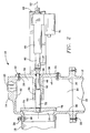
- Figure 2 illustrates a compressor inlet valve 10 for a gas compressor 12.
- the inlet valve serves both to regulate the throughput or capacity of the compressor and also to prevent backflow in the compressor.
- backflow shall mean any gas or gas/oil combination.
- the valve 10 replaces discrete check valves in the service and oil lines of compressed air systems known in the art. Conventional discrete check valves prevent backflow in known compressed air systems.
- the inlet valve is in fluid communication with a compressor 12.
- the inlet valve is used in combination with an oil-flooded, rotary screw compressor.
- the inlet valve may also be used in combination with a non-lubricated rotary screw compressor.
- the compressor includes a compressor inlet 21 and discharge port 25.
- the inlet valve 10 includes an inlet housing 14 which has a housing inlet 16 which communicates with inlet ducting 18, a housing discharge port 20 which is flow connected to a compressor inlet 21 by conventional connection means 22, and an anti-rumble gas inlet 23.
- the anti-rumble inlet must extend through the housing at a location away from the housing inlet 16 as shown in Figure 2.
- the inlet ducting 18 is connected to the housing inlet 16 by a conventional clamping apparatus 24.
- the housing 14 also includes housing opening 26, which extends through the housing opposite the housing inlet.
- a first interior surface 28 defines the housing inlet through which low pressure gas such as air flows into the housing.
- a second interior surface 30 defines the housing discharge port through which the low pressure gas exits the inlet valve housing and flows to the compressor and through which backflow flows from the compressor.
- a third interior surface 32 defines a substantially cylindrical inlet chamber 34 which fluidly communicates with the housing inlet 16 and discharge port 20.
- the housing inlet is surrounded by a valve seat 36 which extends away from the inlet 16 towards an inlet chamber 34 as shown in Figure 3.
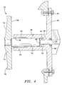
- a mounting plate 38 is adapted to be seated in the housing opening 26. As shown in Figure 4, a conventional gasket member is sandwiched between the periphery of the mounting plate and the housing 14, when the plate is secured to the housing by conventional fasteners 42.
- the mounting plate has a first face 44 and a second face 46.
- a guide member 48 is made integral with the mounting plate 38 along the second face 46. When the mounting plate is seated in the opening 26, the guide member is located within the inlet chamber 34 with a guide member free end 50 positioned away from the housing opening 26 and second face 46 facing the inlet chamber 34.
- a bore 52 extends along longitudinal axis 53 through the guide and plate and has discrete lengths with different diameters. The discrete diameters of the bore 52 are shown in Figure 4.
- the bore 52 forms an opening 54 on the first plate face 44 and also forms an opening 56 at the guide member free end 50.
- a seal 60 such as a lip seal, is disposed in the portion of the bore 52 between the shoulder 58 and opening 54, and a bushing 64 is disposed in the bore at the free end 50 of the guide member 48.
- a valve member 70 is movable, relative to the guide member, within housing chamber 34 and along a predetermined path defined by axis 53.
- the path has a first limiting position where the valve member is in a substantially occluding position relative to housing inlet 16, see Figure 2, and a second limiting position where the valve member is in a substantially non-occluding position relative to the housing inlet, see Figure 3.
- the valve member includes a poppet 71 and a valve stem 72 which is threadably connected to the poppet so that the stem and poppet are movable together within the chamber 34 and along the predetermined path.
- the valve stem is located in the bore 52 and includes a contact end 73 which is positioned within the bore 52 near the shoulder 58.
- the poppet and valve stem are movable linearly along the predetermined path. Additionally, during operation of the compressor, in order to obtain the desired compressed gas discharge pressure, the valve member may be located at any location along the predetermined path, between the first and second limiting positions.
- the poppet 71 includes a leading face 74, a trailing face 76 and a valve stop 78 along the periphery of the leading face of the poppet.
- the stop is adapted to abut the housing seat 36 in the manner shown in Figure 2 when the valve is in the substantially occluding position.
- a drive 80 is a linear actuator that replaces the pneumatic and hydraulic drives and stepper motors that are well known in the art.
- the linear actuator includes a direct current (DC) powered electric motor 81 that extends and retracts an actuator 82 along axis 53.
- DC direct current
- Conventional gearing provides the required gear ratios (typically 10:1) between the actuator and the motor.
- the actuator thrust is provided using a ball screw mechanism that is known in the art.
- the linear drive is designed to provide at least 1000 pounds (453.6 kg) of thrust to the actuator 82.
- the linear drive may be of the type manufactured by Warner Electric Corporation which provides at least 1000 pounds (453.6 kg) of actuator thrust force.
- the terms linear actuator or linear drive shall mean an apparatus having a motor that displaces an actuator member linearly when power is supplied to the motor.
- the linear actuator is in communication with a controller 100 which is described in detail hereinafter.
- a bracket 90 supports the linear actuator 80 and encloses a portion of actuator extension 84.
- the actuator extension is connected to the end of the actuator 82 and is moveable linearly, along the axis 53 with the actuator.
- the bracket includes an open end 95, a closed end 96, sidewalls 92 having longitudinal slots 93, and flange portions 94 at the open end.
- the flanges are mounted, in a conventional manner, on the first face 44 of the mounting plate 38.
- the actuator extension 84 is connected to the actuator 82 by an anti-rotation pin 97, the respective ends of which are located in slots 93 to be movable linearly in the slots during extension and retraction of the actuator and actuator extension.
- Lugs 99 are mounted on the closed end 96 and are adapted to receive the ends of a second pin, like pin 97. In this way, rotation and displacement of the rear portion of linear actuator 80 is prevented.
- the actuator extension contact end 86 is adapted to abut the contact end 73.
- the actuator extension 84 extends through the bracket open end 95 to a location within the bore 52 with the actuator extension end 86 located immediately proximate or in abutment with the valve stem contact end 73.
- valve stem and actuator extension are not connected. Therefore, when it is necessary to close the valve, the actuator and actuator extension are together extended and moved toward the inlet 16 and the actuator extension end 86 abuts the valve stem end 73 and by this abutment, urges the valve member 70 along the predetermined path, toward the inlet 16. However, since the stem and valve are not connected, when the actuator extension and actuator are retracted and moved away from the inlet 16, the actuator extension does not pull the valve member 70 away from the inlet 16.
- Pressure sensing means 98 is located in pressure sensing communication with a separator tank 104 and senses the discharge pressure of the compressed gas. Additionally, the sensing means generates a signal in response to the discharge pressure sensed by the pressure sensing means. As shown schematically in Figure 1, the pressure sensing means is in signal transmitting communication with the electronic microprocessor based controller 100 so that the generated signal is communicated to the controller.
- the sensing means may be a pressure transducer or the like.
- controller 100 is located in signal receiving relation with respect to the pressure sensing means 98, and is located in both signal transmitting and receiving relation with respect to the linear actuator 80.
- the controller is located in signal transmitting relation to a solenoid valve 102.
- a desired operational discharge pressure for a specific application hereinafter referred to as "set point" pressure is programmed in the logic stored in the controller.
- the set point pressure represents the desired compressor discharge pressure.
- Also programmed in the controller is a variable deadband pressure range.
- the deadband range represents the acceptable pressure range which includes the set point pressure. For example, if the set point pressure is 115 psi (792.93 kN/m 2 ), and the acceptable variation in the set point pressure is ⁇ 5 psi (34.48 kN/m 2 ), the acceptable pressure range or deadband range would be 110 psi to 120 psi (758.45 - 827.40 kN/m 2 ) .
- a conventional separator tank 104 is in fluid communication with the compressor discharge port and serves to separate a fluid, such as oil, from the compressed gas.
- the essentially dry gas flowing from the tank may flow to the customer via a service valve 106 or may be redirected to the anti-rumble inlet 23.
- the solenoid valve 102 is flow connected to the separator tank 104.
- the solenoid is actuated by the controller and opens the anti-rumble valve permitting gas exiting the tank to be reflowed to the compressor inlet and in this way, prevent vibration of the rotors referred to in the art as rumble condition.
- a minimum pressure valve 105 is in flow communication with the interior of the separator tank. The minimum pressure valve maintains a minimum pressure in the tank in order to maintain oil flowing through the compressor.
- a set point discharge pressure is entered into the controller where it is stored.
- the acceptable variation in the set point pressure is also entered and stored in the controller.
- the sensor 98 is located in pressure sensing communication with the interior of the tank 104.
- the valve member 70 is in a substantially occluding position when the compressor 12 is started.
- the actuator 82 is extended and the contact end 86 of the actuator extension 84 is in abutment with the contact end 73 and thereby maintains the valve in the substantially occluding position shown in Figure 2 during startup.
- the solenoid valve 102 is actuated by the controller 100 thereby permitting anti-rumble gas to flow through the anti-rumble inlet 23 to the compressor 12.
- the solenoid valve 102 remains open until the valve member 70 is opened. After the compressor has been started, and is warmed up, power is supplied to the linear actuator motor 81 which retracts the actuator 82 along the axis 53 and away from the inlet 16. As the actuator extension is moved away from the inlet, gas drawn through the inlet 16 acts against the face 74, and the greater pressure on face the 74, as compared to the face 76, forces the valve member 70 away from the housing inlet 16. As the valve member 70 is moved away from the inlet 16, the solenoid valve 102 is closed by the controller. The resultant pressure, representing the difference between the flow pressures acting on faces 74 and 76, moves the valve away from the inlet 16, until the contact end 73 abuts the end 86 of the actuator extension 84.
- the inlet vacuum in the cavity 34 decreases as the inlet valve is opened as gas is drawn into the housing by the compressor.
- the discharge pressure is continuously monitored by the sensing means 98 which generates a signal in response to the sensed pressure and communicates the signal to the controller 100.
- the controller executes a preprogrammed logic routine and compares the sensed pressure to the preprogrammed acceptable pressure range.
- the actuator is retracted until the discharge pressure is in the acceptable range.
- the motor 81 is turned off by the controller and further displacement of the valve member away from the inlet 16 is prevented by the stationary actuator extension 84.
- the linear actuator rapidly and accurately permits the valve member to move along the predetermined path to the position required to produce an acceptable discharge pressure.
- the proper position is determined by the measured discharge pressure.
- the proper position typically is located along the path between the occluding and non-occluding positions.
- the valve member is moved away from the inlet 16 when the pressure is below the acceptable range and it is necessary to increase the load to the compressor.
- the controller receives a locked rotor current from the linear drive, indicating the actuator has reached the end of travel. Then power to the DC motor is interrupted causing the motor to shut off.
- the locked rotor current includes a direction signal which indicates the direction of travel of the actuator to the controller. In this way the controller microprocessor can determine electronically if the valve member has reached the end of travel in the non-occluding or occluding position.
- the controller supplies power to the motor 81 which extends the actuator 82 and simultaneously moves the actuator extension along axis 53, toward the inlet 16.
- the contact end 86 of the actuator extension abuts the contact end 73 and thereby urges the valve member along the predetermined path of movement toward the inlet.
- the pressure sensor continuously monitors discharge pressure in the manner previously described and the actuator is extended until the discharge pressure falls into the acceptable pressure range, at which time the controller interrupts power to the motor.
- the actuator provides a thrust that is of sufficient magnitude to overcome the pressure of the gas or air drawn into the housing inlet.
- a locked rotor current like the locked rotor current previously described is transmitted from the linear actuator and is received by the controller.
- the supply of power to the motor is interrupted and the solenoid valve 102 is opened permitting anti-rumble air to the compressor 12.
- Movement of the valve member is determined solely by the discharge pressure of the compressor.
- the valve member 70 is opened or closed based on the measured compressed gas discharge pressure. Based on the measured discharge pressure, the valve member may be moved along the predetermined path and located at the occluding position, the non-occluding position or at a position along the path therebetween.
- valve member 70 When the compressor is stopped, backflow will flow from the compressor out compressor inlet 21. If the valve member 70 is open, the backflow flows against the trailing face 76 of the valve member in the manner indicated by the arrows 67 in Figure 6. The backflow rapidly moves the valve into the substantially occluding position shown in Figure 6. The higher pressure on the face 76, as opposed to face 74, closes the valve member. In this way, the flow of oil and gas from the compressor and out the housing inlet is prevented.
- ends 73 and 86 are moved out of abutment. The two ends remain out of abutment until the compressor is turned on, gas is again drawn through the housing inlet and the valve member is forced away from the inlet in the manner previously described.
Landscapes
- Engineering & Computer Science (AREA)
- Mechanical Engineering (AREA)
- General Engineering & Computer Science (AREA)
- Physics & Mathematics (AREA)
- Fluid Mechanics (AREA)
- Applications Or Details Of Rotary Compressors (AREA)
- Check Valves (AREA)
- Servomotors (AREA)
- Compressor (AREA)
- Electrically Driven Valve-Operating Means (AREA)
Applications Claiming Priority (2)
| Application Number | Priority Date | Filing Date | Title |
|---|---|---|---|
| US512379 | 1995-08-07 | ||
| US08/512,379 US5540558A (en) | 1995-08-07 | 1995-08-07 | Apparatus and method for electronically controlling inlet flow and preventing backflow in a compressor |
Publications (2)
| Publication Number | Publication Date |
|---|---|
| EP0758055A1 true EP0758055A1 (fr) | 1997-02-12 |
| EP0758055B1 EP0758055B1 (fr) | 2004-03-03 |
Family
ID=24038848
Family Applications (1)
| Application Number | Title | Priority Date | Filing Date |
|---|---|---|---|
| EP96305787A Expired - Lifetime EP0758055B1 (fr) | 1995-08-07 | 1996-08-06 | Dispositif et procédé pour commander électroniquement le débit d'entrée et empêcher le reflux dans un compresseur |
Country Status (5)
| Country | Link |
|---|---|
| US (1) | US5540558A (fr) |
| EP (1) | EP0758055B1 (fr) |
| JP (1) | JP3040950B2 (fr) |
| CA (1) | CA2182446C (fr) |
| DE (1) | DE69631724D1 (fr) |
Cited By (1)
| Publication number | Priority date | Publication date | Assignee | Title |
|---|---|---|---|---|
| EP1427941A4 (fr) * | 2001-08-30 | 2006-04-05 | Ingersoll Rand Co | Motocompresseur |
Families Citing this family (47)
| Publication number | Priority date | Publication date | Assignee | Title |
|---|---|---|---|---|
| US6047557A (en) * | 1995-06-07 | 2000-04-11 | Copeland Corporation | Adaptive control for a refrigeration system using pulse width modulated duty cycle scroll compressor |
| US5899435A (en) * | 1996-09-13 | 1999-05-04 | Westinghouse Air Brake Co. | Molded rubber valve seal for use in predetermined type valves, such as, a check valve in a regenerative desiccant air dryer |
| US5820352A (en) * | 1997-03-24 | 1998-10-13 | Ingersoll-Rand Company | Method for controlling compressor discharge pressure |
| US5967757A (en) * | 1997-03-24 | 1999-10-19 | Gunn; John T. | Compressor control system and method |
| US6206652B1 (en) | 1998-08-25 | 2001-03-27 | Copeland Corporation | Compressor capacity modulation |
| US6358045B1 (en) | 1998-01-14 | 2002-03-19 | Ormco Corporation | Self ligating orthodontic bracket |
| DE19841631C2 (de) * | 1998-09-11 | 2002-02-28 | Daimler Chrysler Ag | Pneumatischer Linearantrieb für kryogene Steuerventile |
| US6079957A (en) * | 1998-11-17 | 2000-06-27 | Spx Corporation | Soft start valve |
| DE19916768A1 (de) | 1999-03-04 | 2000-09-14 | Kaeser Kompressoren Gmbh | Vorrichtung und Verfahren zur Regelung eines Kompressors durch Drosselung des Ansaugvolumenstroms |
| US6929238B2 (en) * | 2000-02-18 | 2005-08-16 | Ga Industries Inc. | Electric motor actuated stop and self-closing check valve |
| US7000230B1 (en) | 2000-06-21 | 2006-02-14 | Microsoft Corporation | Network-based software extensions |
| US6883168B1 (en) | 2000-06-21 | 2005-04-19 | Microsoft Corporation | Methods, systems, architectures and data structures for delivering software via a network |
| US7624356B1 (en) | 2000-06-21 | 2009-11-24 | Microsoft Corporation | Task-sensitive methods and systems for displaying command sets |
| US6520205B1 (en) | 2000-08-22 | 2003-02-18 | Ingersoll-Rand Company | Compressor unloader system |
| US6431210B1 (en) | 2001-03-27 | 2002-08-13 | Ingersoll-Rand Company | Inlet unloader valve |
| US7007447B2 (en) * | 2002-11-07 | 2006-03-07 | North American Clutch Corporation | Actuator device with a multi-chamber housing |
| US7153106B2 (en) * | 2003-01-16 | 2006-12-26 | R. Conrader Company | Air compressor unit inlet control |
| US7275216B2 (en) | 2003-03-24 | 2007-09-25 | Microsoft Corporation | System and method for designing electronic forms and hierarchical schemas |
| US7415672B1 (en) | 2003-03-24 | 2008-08-19 | Microsoft Corporation | System and method for designing electronic forms |
| US7370066B1 (en) | 2003-03-24 | 2008-05-06 | Microsoft Corporation | System and method for offline editing of data files |
| US7913159B2 (en) | 2003-03-28 | 2011-03-22 | Microsoft Corporation | System and method for real-time validation of structured data files |
| WO2004094822A2 (fr) * | 2003-04-22 | 2004-11-04 | R. Conrader Company | Compresseur d'air a mecanisme de regulation d'entree d'air et mecanisme de regulation d'entree automatique |
| US7406660B1 (en) | 2003-08-01 | 2008-07-29 | Microsoft Corporation | Mapping between structured data and a visual surface |
| US7334187B1 (en) | 2003-08-06 | 2008-02-19 | Microsoft Corporation | Electronic form aggregation |
| US7028822B2 (en) * | 2003-08-13 | 2006-04-18 | North American Clutch Corporation | Integrated actuator assembly |
| EP1691075B1 (fr) * | 2003-11-14 | 2012-01-11 | Eagle Industry Co., Ltd. | Vanne de commande de capacite |
| JP3904002B2 (ja) * | 2004-06-18 | 2007-04-11 | ダイキン工業株式会社 | 振動式圧縮機 |
| US8487879B2 (en) | 2004-10-29 | 2013-07-16 | Microsoft Corporation | Systems and methods for interacting with a computer through handwriting to a screen |
| US20060158023A1 (en) * | 2005-01-14 | 2006-07-20 | The Boler Company | Continuous radius axle and fabricated spindle assembly |
| US7937651B2 (en) | 2005-01-14 | 2011-05-03 | Microsoft Corporation | Structural editing operations for network forms |
| US8010515B2 (en) | 2005-04-15 | 2011-08-30 | Microsoft Corporation | Query to an electronic form |
| US8200975B2 (en) | 2005-06-29 | 2012-06-12 | Microsoft Corporation | Digital signatures for network forms |
| DE102005040921B4 (de) * | 2005-08-30 | 2008-10-23 | Dienes Werke für Maschinenteile GmbH & Co KG | Trockenlaufender Schraubenverdichter mit pneumatisch gesteuertem Entlüftungsventil |
| US8001459B2 (en) | 2005-12-05 | 2011-08-16 | Microsoft Corporation | Enabling electronic documents for limited-capability computing devices |
| ITGE20060067A1 (it) * | 2006-06-28 | 2007-12-29 | Dott Ing Mario Cozzani Srl | Apparato per la regolazione continua della portata di compressori alternativi. |
| AU2007292454B2 (en) * | 2006-09-05 | 2013-07-18 | New York Air Brake Llc | Oil-free air compressor system with inlet throttle |
| US8157538B2 (en) | 2007-07-23 | 2012-04-17 | Emerson Climate Technologies, Inc. | Capacity modulation system for compressor and method |
| US20090313743A1 (en) * | 2008-06-20 | 2009-12-24 | Craig Jason Hofmeyer | Pants with saggy pants control system |
| BRPI1007407A2 (pt) * | 2009-01-27 | 2016-02-16 | Emerson Climate Technologies | sistema e método de descarregamento para um compressor |
| US8613607B2 (en) * | 2010-03-31 | 2013-12-24 | Fred Rusty Darsey | Pressure pulsation dampener |
| BE1019299A3 (nl) * | 2010-04-20 | 2012-05-08 | Atlas Copco Airpower Nv | Wekwijze voor het aansturen van een compressor. |
| JP6329793B2 (ja) * | 2014-03-26 | 2018-05-23 | 株式会社フジキン | 逆止弁 |
| KR101661225B1 (ko) * | 2014-09-26 | 2016-09-29 | (주)포웰 | 하수관거의 역류 방지 시스템 |
| CN105889051B (zh) * | 2015-02-16 | 2019-11-15 | 创科(澳门离岸商业服务)有限公司 | 用于空气压缩机的进气口控制 |
| BE1025384B1 (nl) | 2017-07-07 | 2019-02-11 | Atlas Copco Airpower Naamloze Vennootschap | Een minimumdrukregelklep en compressor omvattende een dergelijke minimumdrukregelklep |
| BE1026140B1 (nl) * | 2018-03-27 | 2019-10-29 | Atlas Copco Airpower Naamloze Vennootschap | Verbeterd minimum drukventiel en werkwijze voor onderhoud van dergelijk ventiel |
| US20230417329A1 (en) * | 2022-06-24 | 2023-12-28 | Clark Equipment Company | Electronic inlet valve for an air compressor assembly |
Citations (4)
| Publication number | Priority date | Publication date | Assignee | Title |
|---|---|---|---|---|
| US3788776A (en) * | 1972-08-10 | 1974-01-29 | Gardner Denver Co | Compressor unloading control |
| DE3106980A1 (de) * | 1980-02-29 | 1982-05-06 | Hitachi, Ltd., Tokyo | Verdichter |
| GB2116754A (en) * | 1982-03-05 | 1983-09-28 | Hoerbiger Ventilwerke Ag | Suction control valve for rotary compressors |
| US5388968A (en) * | 1994-01-12 | 1995-02-14 | Ingersoll-Rand Company | Compressor inlet valve |
Family Cites Families (12)
| Publication number | Priority date | Publication date | Assignee | Title |
|---|---|---|---|---|
| US2040964A (en) * | 1931-09-15 | 1936-05-19 | Westinghouse Electric & Mfg Co | Unloader valve for fluid compressors |
| US2961147A (en) * | 1958-04-07 | 1960-11-22 | Westinghouse Air Brake Co | Control system for fluid compressors |
| US4052135A (en) * | 1976-05-11 | 1977-10-04 | Gardner-Denver Company | Control system for helical screw compressor |
| US4396345A (en) * | 1981-05-07 | 1983-08-02 | Ingersoll-Rand Company | Unloader valve having bypass valving means |
| US4523436A (en) * | 1983-12-22 | 1985-06-18 | Carrier Corporation | Incrementally adjustable electronic expansion valve |
| US4919390A (en) * | 1987-12-29 | 1990-04-24 | Hitachi Construction Machinery Co., Ltd. | Solenoid operated valve apparatus |
| JPH0255892A (ja) * | 1988-08-19 | 1990-02-26 | Kobe Steel Ltd | スクリュ式真空ポンプ |
| FI83808C (fi) * | 1988-10-05 | 1991-08-26 | Tampella Oy Ab | Foerfarande foer styrning av luftproduktionen i en skruvkompressor. |
| JPH0724711Y2 (ja) * | 1988-12-27 | 1995-06-05 | 株式会社小松製作所 | 電気式油圧比例制御弁 |
| US4968221A (en) * | 1989-04-03 | 1990-11-06 | Dresser Industries, Inc. | Intake valve for vacuum compressor |
| US4945941A (en) * | 1990-03-05 | 1990-08-07 | Vilter Manufacturing Corporation | Means to reduce vibration in check valves and stop/check valves caused by pulsating low fluid flow |
| JP2908613B2 (ja) * | 1991-08-31 | 1999-06-21 | 北越工業株式会社 | 吸気閉塞型アンローダ |
-
1995
- 1995-08-07 US US08/512,379 patent/US5540558A/en not_active Expired - Lifetime
-
1996
- 1996-07-31 CA CA002182446A patent/CA2182446C/fr not_active Expired - Fee Related
- 1996-08-06 DE DE69631724T patent/DE69631724D1/de not_active Expired - Lifetime
- 1996-08-06 EP EP96305787A patent/EP0758055B1/fr not_active Expired - Lifetime
- 1996-08-06 JP JP8206743A patent/JP3040950B2/ja not_active Expired - Fee Related
Patent Citations (4)
| Publication number | Priority date | Publication date | Assignee | Title |
|---|---|---|---|---|
| US3788776A (en) * | 1972-08-10 | 1974-01-29 | Gardner Denver Co | Compressor unloading control |
| DE3106980A1 (de) * | 1980-02-29 | 1982-05-06 | Hitachi, Ltd., Tokyo | Verdichter |
| GB2116754A (en) * | 1982-03-05 | 1983-09-28 | Hoerbiger Ventilwerke Ag | Suction control valve for rotary compressors |
| US5388968A (en) * | 1994-01-12 | 1995-02-14 | Ingersoll-Rand Company | Compressor inlet valve |
Cited By (1)
| Publication number | Priority date | Publication date | Assignee | Title |
|---|---|---|---|---|
| EP1427941A4 (fr) * | 2001-08-30 | 2006-04-05 | Ingersoll Rand Co | Motocompresseur |
Also Published As
| Publication number | Publication date |
|---|---|
| CA2182446C (fr) | 1999-09-28 |
| CA2182446A1 (fr) | 1997-02-08 |
| JP3040950B2 (ja) | 2000-05-15 |
| DE69631724D1 (de) | 2004-04-08 |
| US5540558A (en) | 1996-07-30 |
| EP0758055B1 (fr) | 2004-03-03 |
| JPH09119375A (ja) | 1997-05-06 |
Similar Documents
| Publication | Publication Date | Title |
|---|---|---|
| EP0758055B1 (fr) | Dispositif et procédé pour commander électroniquement le débit d'entrée et empêcher le reflux dans un compresseur | |
| CN100334352C (zh) | 压缩机的诊断系统 | |
| JP3959437B2 (ja) | 容量調整機構を備えたスクロール式機械 | |
| EP0464315B1 (fr) | Compresseur à vis avec surcroît d'huile | |
| KR100350744B1 (ko) | 스쿠루압축기의용량제어용밸브시스템및밸브제조법 | |
| US9329603B2 (en) | Vacuum pressure regulation system | |
| EP0811123B1 (fr) | Distributeur a tiroir actionne par un gaz pour compresseur a vis | |
| EP1052463B1 (fr) | Robinet détendeur | |
| KR100325916B1 (ko) | 가변 용량형 사판식 압축기 및 용량 제어 밸브 | |
| JP5283619B2 (ja) | 往復動圧縮機の流量連続調節用装置 | |
| US4515540A (en) | Variable liquid refrigerant injection port locator for screw compressor equipped with automatic variable volume ratio | |
| KR20050056980A (ko) | 용량 제어형 압축기 | |
| US5639224A (en) | Device for monitoring pressure or temperature in a compressor | |
| US5139051A (en) | Unloading valve for an air compressor system | |
| EP0142945B1 (fr) | Dispositif pour commander la capacité volumétrique d'un compresseur à vis | |
| US4553911A (en) | Method of coding the oil in screw compressors equipped with automatic variable volume ratio | |
| KR100248936B1 (ko) | 차단기의 유체압구동장치 | |
| GB2282642A (en) | Variable volume screw compressor | |
| JPS6356439B2 (fr) | ||
| JPH0310039B2 (fr) | ||
| JPH0260875B2 (fr) |
Legal Events
| Date | Code | Title | Description |
|---|---|---|---|
| PUAI | Public reference made under article 153(3) epc to a published international application that has entered the european phase |
Free format text: ORIGINAL CODE: 0009012 |
|
| AK | Designated contracting states |
Kind code of ref document: A1 Designated state(s): BE DE FR GB IT |
|
| 17P | Request for examination filed |
Effective date: 19970412 |
|
| 17Q | First examination report despatched |
Effective date: 19980202 |
|
| GRAH | Despatch of communication of intention to grant a patent |
Free format text: ORIGINAL CODE: EPIDOS IGRA |
|
| GRAS | Grant fee paid |
Free format text: ORIGINAL CODE: EPIDOSNIGR3 |
|
| GRAA | (expected) grant |
Free format text: ORIGINAL CODE: 0009210 |
|
| AK | Designated contracting states |
Kind code of ref document: B1 Designated state(s): BE DE FR GB IT |
|
| PG25 | Lapsed in a contracting state [announced via postgrant information from national office to epo] |
Ref country code: IT Free format text: LAPSE BECAUSE OF FAILURE TO SUBMIT A TRANSLATION OF THE DESCRIPTION OR TO PAY THE FEE WITHIN THE PRESCRIBED TIME-LIMIT;WARNING: LAPSES OF ITALIAN PATENTS WITH EFFECTIVE DATE BEFORE 2007 MAY HAVE OCCURRED AT ANY TIME BEFORE 2007. THE CORRECT EFFECTIVE DATE MAY BE DIFFERENT FROM THE ONE RECORDED. Effective date: 20040303 Ref country code: FR Free format text: LAPSE BECAUSE OF FAILURE TO SUBMIT A TRANSLATION OF THE DESCRIPTION OR TO PAY THE FEE WITHIN THE PRESCRIBED TIME-LIMIT Effective date: 20040303 Ref country code: BE Free format text: LAPSE BECAUSE OF FAILURE TO SUBMIT A TRANSLATION OF THE DESCRIPTION OR TO PAY THE FEE WITHIN THE PRESCRIBED TIME-LIMIT Effective date: 20040303 |
|
| REG | Reference to a national code |
Ref country code: GB Ref legal event code: FG4D |
|
| REF | Corresponds to: |
Ref document number: 69631724 Country of ref document: DE Date of ref document: 20040408 Kind code of ref document: P |
|
| PG25 | Lapsed in a contracting state [announced via postgrant information from national office to epo] |
Ref country code: DE Free format text: LAPSE BECAUSE OF FAILURE TO SUBMIT A TRANSLATION OF THE DESCRIPTION OR TO PAY THE FEE WITHIN THE PRESCRIBED TIME-LIMIT Effective date: 20040604 |
|
| PGFP | Annual fee paid to national office [announced via postgrant information from national office to epo] |
Ref country code: FR Payment date: 20040819 Year of fee payment: 9 |
|
| PLBE | No opposition filed within time limit |
Free format text: ORIGINAL CODE: 0009261 |
|
| STAA | Information on the status of an ep patent application or granted ep patent |
Free format text: STATUS: NO OPPOSITION FILED WITHIN TIME LIMIT |
|
| EN | Fr: translation not filed | ||
| 26N | No opposition filed |
Effective date: 20041206 |
|
| PGFP | Annual fee paid to national office [announced via postgrant information from national office to epo] |
Ref country code: GB Payment date: 20090825 Year of fee payment: 14 |
|
| GBPC | Gb: european patent ceased through non-payment of renewal fee |
Effective date: 20100806 |
|
| PG25 | Lapsed in a contracting state [announced via postgrant information from national office to epo] |
Ref country code: GB Free format text: LAPSE BECAUSE OF NON-PAYMENT OF DUE FEES Effective date: 20100806 |