EP0758209B1 - Staubfilterbeutel für einen staubsauger - Google Patents
Staubfilterbeutel für einen staubsauger Download PDFInfo
- Publication number
- EP0758209B1 EP0758209B1 EP95917947A EP95917947A EP0758209B1 EP 0758209 B1 EP0758209 B1 EP 0758209B1 EP 95917947 A EP95917947 A EP 95917947A EP 95917947 A EP95917947 A EP 95917947A EP 0758209 B1 EP0758209 B1 EP 0758209B1
- Authority
- EP
- European Patent Office
- Prior art keywords
- filter bag
- dust filter
- bag according
- closure flap
- holding plate
- Prior art date
- Legal status (The legal status is an assumption and is not a legal conclusion. Google has not performed a legal analysis and makes no representation as to the accuracy of the status listed.)
- Expired - Lifetime
Links
Images



Classifications
-
- A—HUMAN NECESSITIES
- A47—FURNITURE; DOMESTIC ARTICLES OR APPLIANCES; COFFEE MILLS; SPICE MILLS; SUCTION CLEANERS IN GENERAL
- A47L—DOMESTIC WASHING OR CLEANING; SUCTION CLEANERS IN GENERAL
- A47L9/00—Details or accessories of suction cleaners, e.g. mechanical means for controlling the suction or for effecting pulsating action; Storing devices specially adapted to suction cleaners or parts thereof; Carrying-vehicles specially adapted for suction cleaners
- A47L9/10—Filters; Dust separators; Dust removal; Automatic exchange of filters
- A47L9/14—Bags or the like; Rigid filtering receptacles; Attachment of, or closures for, bags or receptacles
-
- A—HUMAN NECESSITIES
- A47—FURNITURE; DOMESTIC ARTICLES OR APPLIANCES; COFFEE MILLS; SPICE MILLS; SUCTION CLEANERS IN GENERAL
- A47L—DOMESTIC WASHING OR CLEANING; SUCTION CLEANERS IN GENERAL
- A47L9/00—Details or accessories of suction cleaners, e.g. mechanical means for controlling the suction or for effecting pulsating action; Storing devices specially adapted to suction cleaners or parts thereof; Carrying-vehicles specially adapted for suction cleaners
- A47L9/10—Filters; Dust separators; Dust removal; Automatic exchange of filters
- A47L9/14—Bags or the like; Rigid filtering receptacles; Attachment of, or closures for, bags or receptacles
- A47L9/1427—Means for mounting or attaching bags or filtering receptacles in suction cleaners; Adapters
- A47L9/1436—Connecting plates, e.g. collars, end closures
- A47L9/1445—Connecting plates, e.g. collars, end closures with closure means
-
- A—HUMAN NECESSITIES
- A47—FURNITURE; DOMESTIC ARTICLES OR APPLIANCES; COFFEE MILLS; SPICE MILLS; SUCTION CLEANERS IN GENERAL
- A47L—DOMESTIC WASHING OR CLEANING; SUCTION CLEANERS IN GENERAL
- A47L9/00—Details or accessories of suction cleaners, e.g. mechanical means for controlling the suction or for effecting pulsating action; Storing devices specially adapted to suction cleaners or parts thereof; Carrying-vehicles specially adapted for suction cleaners
- A47L9/10—Filters; Dust separators; Dust removal; Automatic exchange of filters
- A47L9/14—Bags or the like; Rigid filtering receptacles; Attachment of, or closures for, bags or receptacles
- A47L9/1427—Means for mounting or attaching bags or filtering receptacles in suction cleaners; Adapters
- A47L9/1436—Connecting plates, e.g. collars, end closures
- A47L9/1445—Connecting plates, e.g. collars, end closures with closure means
- A47L9/1454—Self-sealing closures, e.g. valves
Definitions
- the invention relates to dust filter bags for a vacuum cleaner, with one made of a solid paper material such as cardboard existing holding plate, with which a dust bag, for example is bonded to one of the inside of the dust bag facing flap hinged to the holding plate, which can be opened against spring action and in the closed state is an opening in the holding plate holds.
- a dust filter bag of this type is through US-A-20 70 674 known.
- a spout with a hat rim is inserted through it. It points in the direction of the blow pipe of the vacuum cleaner protruding and tapering in this direction funnel-shaped. Protrudes into this funnel opening free-standing a blow nozzle.
- the hat edge serves with the the plate-side surface of the support of the spout on Opening edge while the inside of the anther facing surface as contact surface or valve seat surface the closure flap acts.
- the self-closing The action of the shutter is based on the restoring force one freely spanning the back of the closure flap Elastic thread. Its two ends are in peripheral clamping slots of the base plate clamped. The position of the elastic thread on the flap side takes place via a cut, angled Tongue. Since the corresponding angulation is a free cut This hole is a dust filter bag not quite tight. If you grasp the filled dust bag air and dust come through this hole out. This solution is also quite complex.
- the object of the invention is a generic Dust filter bag structurally simpler and more user-friendly train more advantageous.
- the spring element brings one so high restoring effect that the so-called self-closing effect is secured in the simplest way. On the other hand, there remains a high level of folding, so that the blow stream is not jammed to prevent operation becomes. The said distance, resulting from the plate thickness the holding plate is also sufficient.
- the Spring element is simply on an outward facing first surface of the flap attached. If necessary the entire area can be used here. This can even go so far that the spring element itself continues in an edge seal of the closure flap, whereby this spring element has another function.
- the spring element would then in this case expediently consist of a rubber layer blank.
- the spring element as a substantially complete the first surface covering layer element is formed, what means that the inner field of the shutter even can be exempted.
- the shutter would exist then from a drum skin-like cover flap frame. This can have a ring shape.
- the weight the closure flap can be reduced in this way.
- one of the contour on the holding plate adapted to the closure flap contact surface is. Such a contour-appropriate adjustment brings an assignment of the closure flap that is gentle on the joint axis, especially in the state of increased mechanical stress, for example, by the contact pressure of the Anthers collected dust particles etc.
- the spring element is an elastic, for example Rubber-elastic band element is spring-back stretched state in the closed position of the Closing flap connects this to the holding plate.
- the appropriate anchoring is simple possible, for example by gluing and or stapling.
- the given, practically selectable preload makes the self-closing effect is even adjustable. A corresponding variation seems favorable in terms of on an individual adaptation to different Vacuum cleaner types. It is further in this context favorable if the band element is about 10% of the elastic Has a corresponding preload, in a closed position of the closure flap.
- the preload can be done right at the beginning, i.e. with the sandwich Mount the mounting plate, namely by correspondingly stretching the restraint-side pull End and definition of the same.
- the bias generating arrangement can be achieved with simple means if the Preload by a protuberance transverse to the direction of extension of the spring element is effected.
- the spring element between two layers the holding plate is held. It is an advantage here that the spring element has a greater width than on the area of hinge-forming interaction between the flap and the holding plate is omitted. The is especially for circular flaps from Meaning.
- the holding plate on its outside in the area the opening a sealing surface for contacting one axially directed end face of a vacuum cleaner blow nozzle having.
- This sealing surface can be in the same smoothed or coated as mentioned above, be printed in particular.
- the printing would be the printing be given preference because this outside of the Holding plate with indications of origin anyway, instructions for use and type designation is printed.
- the opening in addition is slide lockable. It can't even do that happen that the user is (unintentionally) Reach into the opening, the flap in the open position can press. Rather, this approach is sealed off.
- the corresponding slide lock is Subject of DE-A-43 41 248 and DE-A-44 13 248.
- the invention also proposes that between the slide and the flap in the holding plate an intermediate plate is formed, in which the opening is located.
- the Blow nozzle on the face of an annular groove for receiving the Has double ring seal the groove base one for Has outer opening subsequent opening.
- the ring seal realized in the form of an axial seal is easy by the slider mentioned Ventilation of the holding plate can be overflowed.
- the so priority occlusion occurs a clean undocking of the Dust filter bag too.
- the passages mentioned cause that according to the different prevailing in the device Vacuum areas in the event of a leak in the docking area, dusts primarily into those that conduct them Paths are drawn.
- the Dust filter bag advantageous that the holding plate in Area of their hinge axis the edge of the closure flap overlapping deflecting edge. The corresponding exposed deflection edge brings with the joint movement a larger amount of stretch length and thus one increased resilience.
- a dust filter bag for a vacuum cleaner with one made of a solid paper material, such as Cardboard, existing holding plate, with which a Dust bag is glued, for example, where the holding plate from a base plate, one on the Base plate placed frame part, one on the base plate and in the frame part forming a guide shaft sliding slide and a cover plate, wherein the cover plate is a window for reaching through Handling end of the slide, it is further advantageous that the slider is a smoothly formed Has broadside and with this broadside on the also smoothly designed broad side of the cover plate lies on. This measure increases the lubricity of the Slider or reduces the corresponding actuation forces.
- the one-sided smoothness can be used Paper material such as cardboard with simple Funds are given.
- the slide has leaf-shaped outline. That reduces his Sliding surface compared to sliders with the same width. It also proves to be favorable that the petiole himself to his free, the slider-taking tab bearing end tapered and the stem leading section of a slide guide shaft corresponds to the lateral and end outline of the stem. Under The side edge of the handle lifts when actuated from the corresponding edge of the slide guide shaft from. This sliding friction is therefore eliminated and favors the desired smooth movement of the Also on the narrow edges. This effect takes place their structural continuation continues in that too the window as a recess corresponding to the stem outline is designed. Specifically, this looks like that the slider take-off protruding into the window with respect to its edges in the direction of sliding corresponds to the taper of the window.
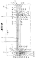
- the dust filter bag shown in the drawings 1 is a so-called disposable or disposable bag.
- the dust filter bag 1 is interchangeable Recording space 2 assigned to a vacuum cleaner 3. It can as can be seen from FIG. 23, a handheld vacuum cleaner act. Whose via a network connection or a battery device electrically powered blower 4 in the form of a motor / blower unit is located in a remote or separate from the recording room 2 Room 5.
- the flow-permeable supporting wall shown for the dust filter bag 1 is designated 6.
- the supporting wall 6 takes a blow nozzle 7 passing through it on, which connects to a suction channel 8. It ends into a suction nozzle 9.
- blower 4 Below the blower 4 is one upwards opening flow deflection 10. Below is a blow-out filter 11. An air outlet connects to the.
- the docking side of the dust filter bag on the blow connector side 1 consists of a holding plate H.
- the latter is multilayer and consists of paper material such as Cardboard.
- a Holding plate H Above the inner side facing away from the blow nozzle 7 a Holding plate H extends a dust bag 12 dust-filtering fleece material. It is on the edge attached to the inside a of the holding plate, for example bonded. The top of the falling aligned dust filter bag 1 tapers.
- the dust bag 12 takes from the one shown in FIG A trapezoidal outline.
- the holding plate H is basically long rectangular. Yours, bringing the flow-side flow passage Opening ⁇ is offset from the center in the end area the one rectangle end zone. The opening ⁇ points circular cross section.
- the edge of the holding plate H can be a not shown uniqueness of the holding plate Contour with the attachment area of the dust bag 12 outgoing fastening sections for secure allocation of the dust filter bag 1 in Vacuum cleaner 3.
- a closure flap 13 is assigned to the opening ⁇ .
- Their geometric hinge axis 14 is on the Cross center of the holding plate H closer side of the Opening ⁇ .
- the articulation is such that the closure flap 13 opens up to the interior 15 of the dust bag 12. This happens under the effect of the blown air flow in Direction of arrow x against a spring action, which strives to keep the shutter in the closed state to keep in what closed state the flap 13 the opening ⁇ in the holding plate H holds.
- a band-like is used for this Spring element F.
- This is attached to the closure flap 13 and anchored to the holding plate. The attachment is such that in the closed state of the flap 13 (see FIG. 4) between a band plane E-E and the hinge axis 14 lying outside the band the closure flap 13 is formed a distance y. The distance y is transverse to the plane of extent Holding plate H.
- the hinge axis 14 is the interior 15 facing the dust bag 12, is therefore on the inside a.
- the spring element F designed as a band is located on an outside, i.e. the outside b of the holding plate H facing first surface 13 'of the closure flap 13.
- the second facing the interior 15 Surface of the closure flap 13 is called 13 ''.
- the band-like spring element F is on the closure flap side attached to the surface 13 ', such as by gluing.
- a section of the band-like spring element F is on the holding plate H attached and designated as anchoring end 16.
- anchoring end 16 Like that Removable drawings, is the spring element F and that at this bondage end 16 formed between two Layers I, II of the multi-layer holding plate H summarized.
- the Fixation can be done there by gluing and / or stapling happen.
- the bondage point 17 of the bondage end 16 is clearly spaced from the hinge axis 14. So remains between this and the aforementioned attachment point 17 an unbonded section of the tape as the expansion reserve 18.
- the latter is at the beginning the opening of the shutter 13 claimed. It is on the in dash-dotted line style referenced opening state shown in Figure 4.
- the spring element F is an elastic, for example rubber-elastic, impermeable band element, which in the resiliently stretched state in the closed position, So the closed state, the closure flap 13 connects this with the holding plate H.
- the spring element F can be made of rubber. Even thermoplastic Elastomers are conceivable, for example SEBS, EPDM. There is therefore a preload. This is predeterminable by choosing the bondage point 17. In the order of magnitude shown, it is sufficient that the Band element say spring element F about 10% of elastic pre-tension corresponding to elastic expansion reserve has, in the closed position of the closure flap 13.
- the edge seal D is a contact surface 19 of the holding plate H opposite. It is from position II of the holding plate H formed. It (19) extends as a circumferential Ring shoulder concentric to opening ⁇ , the lights Diameter is smaller than that in position I. Opening 20 of the holding plate H.
- the closure flap 13 is adapted to the opening contour of the opening 20, the peripheral front edge 13 '' 'of the closure flap 13 thus supported against the contact surface 19, of course, taking into account the ability to fold the closure flap receiving the access to the the hinge point 14 diametrically opposite side or half of the arc of the basically circular closure flap.
- the joint is due to the mere attachment of the front edge 13 '' 'floating and self-regulating.
- the folding abutment of the spring-loaded closure flap 13 defining contact surface 19 is in view trained on the edge seal D.
- the cardboard-paper material so the location II, with regard to the contact surface 19 a greater smoothness is machined or coated.
- FIGS. 7 and 8. There results the roughening of the contact surface 19, designated 22 from the correspondingly enlarged excerpt A. Die by exaggerated strange relief structure depicted roughening 22 can be smoothed by punching pressure or as shown in Figure 8, by a coating 23 (black tips). The roughness 22 is through filled in the coating. This is preferred by a printing of the contact surface 19 accomplished.
- a corresponding sealing measure is also related made on the bottom, in the area of Docking zone of the blow nozzle 7.
- the docking zone of the holding plate H points to the blow nozzle 7 facing Outside b a sealing surface 24 on to bear one Axial seal.
- the axial seal is on one axially directed, ie pointing towards the opening ⁇ End face 25 of the vacuum cleaner blow connector 7.
- the axial seal is from a double ring seal 26 formed in a corresponding face of the blow nozzle 7 lying ring groove 27 is embedded.
- double ring seal 26 it is about a U-shaped element in cross section. Whose U opening points upwards, corresponding to that of the U-legs formed two sealing lips 28 and 29.
- the upward ends of the sealing lips 28, 29 are rounded across and occur in a manner appropriate to the operation Assignment of the dust filter bag 1 or the holding plate H closing against the corresponding underside Sealing surface 24, which the bearing surface 19th vertically opposite.
- the sealing surface 24 is in smoothed in the same way as the contact surface 19.
- the side of the opening ⁇ facing the blow nozzle 7 can be closed by a slide 30.
- the latter is below the number II Location.
- To form a guide shaft 31 for the Slider 30 are the holding plate H two more layers, namely designated with III and IV assigned. All can be the same thickness.
- the corresponding laminate results can be clearly seen in Figure 4. While the subsequent position II third layer III up to the area of Opening the opening backdrop forms the fourth Position the underside cover of the guide shaft 31, of course leaving one concentric to the Opening ⁇ or opening 20 lying opening 32.
- the latter is dimensioned in its clear diameter so that the double ring seal 26 can reach through in Sealing system to join sealing surface 24.
- the bottom layer IV has a window 35.
- a slide-driving projection 36 is sufficient for one automatic actuator as it is made out the mentioned DE-A-43 41 248 and DE-A-44 13 248 results.
- the slide 30 is a to completely close the opening ⁇ , stroke defined stroke.
- the holding plate is used to initiate the slide lock H as seen in Figure 9, slightly from the blow nozzle 7 raised upwards, just as far, that the slider acting like a cigar cutter 30 freely run over the head of the sealing lips 28, 29 can.
- the outer rib 28 still seals down to the opening 32. This prevents dust from escaping.
- the dust bag 1 according to the second embodiment is basically the same structure; it's about there but a slide-free solution.
- the reference numbers are applied analogously, without repetitions.
- the extension area Bar 38 Said in the extension area Bar 38 is a recess or slot-like Opening 39, which the protruding section picks up and so pre-stretches the layer element so that the Front edge 13 '' 'of the joint side on the joint side or half of the flap 13 firmly against the the edge zone of the opening 20 is drawn with the Effect of the desired closing component of the closure flap 13.
- the turned out section 40 a trapezoidal detour.
- the strip 38 can be made by fitting a corresponding Steges be realized (dash-dotted version) or, as shown in full line, through the breakthrough side directed expression of the relevant Section II.
- the first variant ( Figures 11 and 12) remains execute that the local flap 13 is not as above consists of a disc-shaped cardboard body, but from an element designed as a ring 41.
- the spring element cut according to the outline here F or layer element now acts like a that Ring-closing eardrum.
- This variant too the articulated gussets 21 indicated above are formed, which over an angular range alpha of about enter a quarter circle into the periphery of the ring.
- the joint gussets 21 spread apart still in the direction of the longitudinal edges of the holding plate H. Das results in an overall fairly large bondage end 16 of the spring element F.
- the second variant differentiates differ from the first only in that the geometric Joint axis 14 not in the area of a pure tangent the longitudinal center plane of the holding plate H is designed, but in a secant. This leads to a clear one Extension of the hinge axis formed there pure ring shape is thus given up in the articulation area, by there a parallel to the axis of the joint Frame leg 42 lies. There could also be one here heraldic outline form are used. The flattening would face the hinge axis 14.
- the shutter 13 can also here consist of a disc element instead of a ring.
- Figure 16 makes it particularly clear that this is in the direction the opening ⁇ facing end of the layer V an exposed Deflection edge 43 creates.
- the corresponding lead causes the stretch supply to stretch for a longer time 18 and thus a stronger restoring force in the sense of spring-loaded closure of the flap 13, the moreover, at least in this area is held in a form-fitting manner in a U-space 44. It requires therefore already a certain flow rate in order to To bring the joint into effect.
- the joint axis-side edge section like a out-of-round cam works.
- passages 46 in the form of channels in the rubber-elastic sealing ring realized.
- Double ring seal 26 consists of the passage 46 an open skin section of an open-pore, elastic Foam.
- the peripheral skin is wearing the reference numeral 47. It covers the outer surface of the Sealing lips 28 and 29 hermetically seal and go inside the chamber 45 to the foot of the sealing lips there 28 and 29.
- the bottom of chamber 45 is open-pored, precisely in the sense of forming the culvert there 46.
- the material forming the holding plate H also exists here made of a solid paper material, such as Cardboard, but at least one side is smooth is.
- the smoothness is due to a leveling structure shown as they are shown in Figures 8 and 22nd already results.
- the parts are added together by adhesive, that the slider 30 with its smoothly formed Broadside, for example a coating 23 an equally smooth broadside of the Cover plate rests, formed by the designated IV Location.
- the slide 30 can be correspondingly easily relocate; which lies as a braking roughness 22 not in this joint area of layers III-IV. Note the falling assignment of the dust filter bag 1, so does the overlying layer II acting load no adverse effect, especially since there is further training in that the back of the slider 30 in turn a smooth one Broadside is facing, namely the one above extending base plate, formed by the layer II.
- the related smoothing is again designated 23.
- the slider 30 is also within one layer III, which, as can be seen from Figure 25, the frame part forms.
- the inside of the frame part forms the one above described guide shaft 31 on which the slide 30 contour-matched and coordinated on the sliding stroke is.
- the petiole or the handling end 34 tapers towards the free end of the stem.
- the outline also shows a taper Handle or the handling end 34 leading section of the slide guide shaft 31.
- This outline equality lies in the basic position shown in FIG in front. Lift towards the closed position the otherwise touching edges of the leading section and that of the handling end 34 from each other and in the opposite direction back into contact with the system, as can be seen in Figure 27. This prevents the closing end from tilting 33, which is otherwise tailored so that a good guided sliding movement remains guaranteed.
- the corresponding taper is not limited only on the part mentioned, but is also related on the slide driving projection 36.
- the latter protrudes into the window 35 of the cover plate, that is, the position IV.
- the window is as the stem outline Cutout realized.
- the window also runs in Direction of the free end of the petiole in width tapering continuously.
- the slide-driving projection protruding into the window 35 36 with respect to its in the direction of displacement lying edges of the taper of the window 35 corresponds.
- the open position shown in FIG. 27 of the slider 30 fills the driving projection 36 the end region of the window there at three connected Form-fitting sides. Because of the rejuvenation The edges 50 therefore also rise in the course of the Closing the opening ⁇ from the corresponding Edges of the window 35 in the sense of the raised Smooth movement of the slide 30.
- the slide-driving projection 36 can be from a layer section be formed, in terms of thickness. Such a section becomes the smooth side of the slider 30 assigned, and also with the smooth Side against it, so that the roughness 22 or rough Broad side of this spot faces outwards. The enables a non-slip grip when operated manually the slide 30 or the safe touch by a driver of an opening / closing device, not shown.
- the adhesive stain holding the slide-driving projection 36 is designated 51.
- Adhesive bead 52 surrounding the edges and covering the layers III and IV connects i.e. frame part and cover plate.
- the base plate ie position II, near the edge equipped with such an adhesive bead 53.
- the latter covers with its smooth coating 23 the roughness 23 of the back of the slide 30 and also the rough back of the frame part, which of the Layer III is formed.
Landscapes
- Engineering & Computer Science (AREA)
- Mechanical Engineering (AREA)
- Filters For Electric Vacuum Cleaners (AREA)
Description
- Fig. 1
- die Halteplatte des Staubfilterbeutels von der Innenseite her gesehen, im Verschlußzustand, gemäß erstem Ausführungsbeispiel,
- Fig. 2
- eine Seitenansicht der Halteplatte,
- Fig. 3
- die Halteplatte von der Außenseite her gesehen,
- Fig. 4
- den Schnitt gemäß Linie IV-IV in Figur 1, gegenüber Figur 1 vergrößert, um den Staubbeutel komplettiert sowie dem Staubsauger betriebsgerecht zugeordnet,
- Fig. 5
- den Staubfilterbeutel in perspektivischer Darstellung bei in Bezug auf einen Schieber freigegebener Öffnung und im Verschließzustand der Verschlußklappe,
- Fig. 6
- eine der Figur 5 entsprechende Darstellung im Zuge der Schließung der besagten Öffnung,
- Fig. 7
- den Staubfilterbeutel im Längsschnitt bei durch die Blasluft geöffneter Verschlußklappe,
- Fig. 8
- die in Figur 7 mit A bezeichnete Stelle in Herausvergrößerung,
- Fig. 9
- einen Längsschnitt bei gegenüber dem Blasstutzen leicht gelüfteter Andockstellung, so daß der Schieber, die dortige Doppel-Ringdichtung überlaufend, Raum findet,
- Fig. 10
- dem Schnitt wie Figur 9, jedoch bei nun die Öffnung verschließendem Schieber,
- Fig. 11
- die Draufsicht auf den öffnungsseitigen Bereich des Staubfilterbeutels unter Darstellung einer ersten Variante der Verschlußklappe (ringförmig),
- Fig. 12
- den Schnitt gemäß Linie XII-XII in Figur 11, angedockt und bei zurückgetretenem Schieber,
- Fig. 13
- eine Darstellung wie Figur 11, jedoch einer zweiten Variante des Staubfilterbeutels (sekantenförmige Anlenkung der Verschlußklappe),
- Fig. 14
- den Schnitt gemäß Linie XIV-XIV in Figur 13,
- Fig. 15
- eine der Figur 13 entsprechende Darstellung, eine dritte Variante des Erfindungsgegenstandes wiedergebend (Gelenkstelle mit Umlenkvorsprung),
- Fig. 16
- den Schnitt gemäß Linie XVI-XVI in Figur 15,
- Fig. 17
- die Halteplatte von der Innenseite her gesehen, im Verschlußzustand, gemäß zweitem Ausführungsbeispiel (schieberfrei),
- Fig. 18
- eine Seitenansicht hierzu,
- Fig. 19
- die Halteplatte von der Außenseite her gesehen,
- Fig. 20
- den betriebsgerecht zugeordneten Staubfilterbeutel im Längsschnitt, und zwar bei durch den Blasstrom geöffneter Verschlußklappe,
- Fig. 21
- die in Figur 20 mit B bezeichnete Einzelheit in Vergrößerung,
- Fig. 22
- die in Figur 20 mit C bezeichnete Einzelheit in Vergrößerung,
- Fig. 23
- einen mit dem erfindungsgemäßen Staubfilterbeutel bestückten Staubsauger in weitestgehend schematischer Darstellung,
- Fig. 24
- in Draufsicht eine eine Deckplatte der Halteplatte bildende Lage in Einzeldarstellung,
- Fig. 25
- eine ein Rahmenteil plus Schieber bildende Lage in Einzeldarstellung,
- Fig. 26
- eine eine Grundplatte bildende Lage der Halteplatte in Einzeldarstellung,
- Fig. 27
- die komplettierte Halteplatte in Draufsicht, nicht schieberverschlossen,
- Fig. 28
- eine gleiche Darstellung wie Figur 27, jedoch partiell schieberverschlossen,
- Fig. 29
- den Schnitt gemäß Linie XXIX-XXIX in Fig. 27,
- Fig. 30
- den Schnitt gemäß Linie XXX-XXX in Fig. 28,
- Fig. 31
- die einzelnen Lagen in zuordnungsgerechter Übereinanderlage zur Bildung der Halteplatte, zur Verdeutlichung der Glättung stark dickenvergrößert, und noch nicht in Aufeinanderlage sowie in Schnittdarstellung gemäß Linie XXXI-XXXI in Figur 27 und
- Fig. 32
- den fertiggestalteten, zugeordneten Staubfilterbeutel, ergänzt um die Verschlußklappe, in Darstellung wie Figur 7, also bei durch die Blasluft geöffneter Verschlußklappe.
Claims (28)
- Staubfilterbeutel (1) für einen Staubsauger (3), mit einer aus einem festen Papierwerkstoff, wie beispielsweise Pappe bestehenden Halteplatte (H), mit welcher ein Staubbeutel (12) beispielsweise klebeverbunden ist, mit einer dem Inneren (15) des Staubbeutels (12) zugewandten, an der Halteplatte (H) angelenkten Verschlußklappe (13), welche gegen eine Federwirkung öffenbar ist und im Verschließzustand eine Öffnung (Ö) in der Halteplatte (H) zuhält, dadurch gekennzeichnet, daß ein bandartiges Federelement (F) an der verschlußklappe (13) derart angebracht ist, daß im Verschließzustand zwischen einem Bandende (E-E) des Federelementes (F) und einer außerhalb des Federelementes (F) liegenden Gelenkachse (14) der Verschlußklappe (13) ein Abstand (y) ausgebildet ist, wobei die Gelenkachse (14) dem Inneren (15) des Staubbeutels (1) zugewandt ausgebildet ist.
- Staubfilterbeutel nach Anspruch 1, dadurch gekennzeichnet, daß das Federelement (F) auf einer nach außen gewandten ersten Oberflache (13') der Verschlußklappe (13) angebracht ist.
- Staubfilterbeutel nach einem oder mehreren der vorhergehenden Ansprüche, dadurch gekennzeichnet, daß das Federelement (F) sich in eine Randdichtung (D) der Verschlußklappe (13) fortsetzt.
- Staubfilterbeutel nach einem oder mehreren der vorhergehenden Ansprüche, dadurch gekennzeichnet, daß das Federelement (F) als ein quer zur Oberfläche (13') im wesentlichen vollständig überdeckendes Lagenelement ausgebildet ist.
- Staubfilterbeutel nach einem oder mehreren der vorhergehenden Ansprüche, dadurch gekennzeichnet, daß an der Halteplatte (H) eine der Kontur der Verschlußklappe (13) angepaßte Anlagefläche (19) ausgebildet ist.
- Staubfilterbeutel nach einem oder mehreren der vorhergehenden Ansprüche, dadurch gekennzeichnet, daß das Federelement (F) ein elastisches, beispielsweise gummielastisches Bandelement ist und im rückfederbar gestreckten Zustand in der Verschlußstellung der Verschlußklappe (13) diese mit der Halteplatte (H) verbindet.
- Staubfilterbeutel nach Anspruch 6, dadurch gekennzeichnet, daß das Bandelement eine etwa 10% des elastischen Dehnungsvorrats entsprechende Vorspannung aufweist, in einer Schließstellung der Verschlußklappe (13).
- Staubfilterbeutel nach Anspruch 7, dadurch gekennzeichnet, daß die Vorspannung durch eine Ausstülpung quer zur Erstreckungsrichtung des Federelements (F) erzielt ist.
- Staubfilterbeutel nach einem oder mehreren der vorhergehenden Ansprüche, dadurch gekennzeichnet, daß das Federelement (F) zwischen zwei Lagen (I,II) der Halteplatte (H) gefaßt ist.
- Staubfilterbeutel nach einem oder mehreren der vorhergehenden Ansprüche, dadurch gekennzeichnet, daß das Federelement (F) eine größere Breite aufweist als auf den Bereich der scharnierbildenden Zusammenwirkung zwischen Verschlußklappe (13) und Halteplatte (H) entfällt.
- Staubfilterbeutel nach einem oder mehreren der vorhergehenden Ansprüche, dadurch gekennzeichnet, daß der Papp-Papierwerkstoff an der Anlagefläche (19) der Verschlußklappe im Hinblick auf eine größere Glätte bearbeitet oder beschichtet ist.
- Staubfilterbeutel nach einem oder mehreren der vorhergehenden Ansprüche, dadurch gekennzeichnet, daß die Anlagefläche (19) bedruckt ist.
- Staubfilterbeutel nach einem oder mehreren der vorhergehenden Ansprüche, dadurch gekennzeichnet, daß die Halteplatte (H) auf ihrer Außenseite (b) im Bereich der Öffnung (Ö) eine Dichtfläche (24) zur Anlage einer axialgerichteten Stirnfläche (25) eines Staubsauger-Blasstutzens (7) aufweist.
- Staubfilterbeutel nach einem oder mehreren der vorhergehenden Ansprüche, dadurch gekennzeichnet, daß die Öffnung (Ö) zusätzlich durch einen Schieber (30) verschließbar ist.
- Staubfilterbeutel nach Anspruch 14, dadurch gekennzeichnet, daß zwischen dem Schieber (30) und der Verschlußklappe (13) in der Halteplatte (H) eine Zwischenplatte ausgebildet ist, in welcher sich die Öffnung (Ö) befindet.
- Staubfilterbeutel nach einem oder mehreren der vorhergehenden Ansprüche, für einen Staubsauger (1) mit einem Gebläse (4), einem Staubsauger-Blasstutzen (7) und einem Aufnahmeraum (2) für den Staubfilterbeutel (1), wobei der Staubsauger-Blasstutzen (7) zur stirnseitigen Anlage an einen in dem Aufnahmeraum (2) aufgenommenen Staubfilterbeutel (1) ausgebildet ist, dadurch gekennzeichnet, daß in der Stirnfläche (25) des Blasstutzens (7) eine Doppel-Ringdichtung (26) ausgebildet ist.
- Staubfilterbeutel nach Anspruch 16, dadurch gekennzeichnet, daß eine bei Anlage zwischen den Dichtlippen (28,29) der Doppel-Ringdichtung (26) und der Halteplatte (H) ausgebildete Kammer (45) einen Durchlaß (46) zum Anschluß an die Atmosphäre hat.
- Staubfilterbeutel nach Anspruch 17, dadurch gekennzeichnet, daß der Durchlaß (46) von Kanälen gebildet ist.
- Staubfilterbeutel nach Anspruch 17 oder 18, dadurch gekennzeichnet, daß der Durchlaß (46) von einem unverhauteten Abschnitt eines offenporigen Schaumstoffes gebildet ist.
- Staubfilterbeutel nach einem oder mehreren der vorhergehenden Ansprüche 16-19, dadurch gekennzeichnet, daß der Blasstutzen (7) stirnseitig eine Ringnut (27) zur Aufnahme der Doppel-Ringdichtung (26) besitzt, deren Nutgrund (48) eine zur Außenfläche anschließende Durchbrechung (49) aufweist.
- Staubfilterbeutel nach einem oder mehreren der vorhergehenden Ansprüche, dadurch gekennzeichnet, daß die Halteplatte (H) im Bereich ihrer Gelenkachse (14) eine den Rand der Verschlußklappe (13) übergreifende Umlenkkante (43) aufweist.
- Staubfilterbeutel nach einem oder mehreren der vorhergehenden Ansprüche, wobei die Halteplatte (H) aus einer Grundplatte (II), einem auf der Grundplatte (II) aufgelegten Rahmenteil (III), einem auf der Grundplatte (II) und in dem einen Führungsschacht (31) bildenden Rahmenteil (III) verschiebbaren Schieber (30) sowie einer Deckplatte (IV) besteht, wobei weiter die Deckplatte (IV) ein Fenster (35) zum Durchgriff auf ein Handhabungsende (34) des Schiebers (30) hat, dadurch gekennzeichnet, daß der Schieber (30) eine glatt ausgebildete Breitseite aufweist und mit dieser Breitseite auf der ebenfalls glatt ausgebildeten Breitseite der Deckplatte (IV) aufliegt.
- Staubfilterbeutel nach Anspruch 22, dadurch gekennzeichnet, daß die Rückseite des Schiebers (30) einer glatt ausgebildeten Breitseite der Grundplatte (II) zugewandt ist.
- Staubfilterbeutel nach Anspruch 22 oder 23, dadurch gekennzeichnet, daß das nach außen weisende breitseitige Handhabungsende (34) des Schiebers (30) einen Schieber-Mitnahmevorsprung (36) trägt, der mit seiner rauhen Breitseite nach auswärts weist.
- Staubfilterbeutel nach einem oder mehreren der vorhergehenden Ansprüche 22-24, dadurch gekennzeichnet, daß der Schieber (30) blattförmigen Umriß aufweist.
- Staubfilterbeutel nach einem oder mehreren der vorhergehenden Ansprüche 22-25, dadurch gekennzeichnet, daß der Blattstiel sich zu seinem freien, den Schieber-Mitnahmevorsprung (36) tragenden Ende hin verjüngt und der den Stiel führende Abschnitt eines Schieber-Führungsschachtes (31) dem Stielumriß entspricht.
- Staubfilterbeutel nach Anspruch 26, dadurch gekennzeichnet, daß auch das Fenster (35) als dem Stielumriß entsprechende Aussparung gestaltet ist.
- Staubfilterbeutel nach Anspruch 27, dadurch gekennzeichnet, daß der in das Fenster (35) ragende Schieber-Mitnahmevorsprung (36) bezüglich seiner in Schieberichtung liegenden Ränder (50) der Verjüngung des Fensters (35) entspricht.
Priority Applications (1)
| Application Number | Priority Date | Filing Date | Title |
|---|---|---|---|
| SI9530129T SI0758209T1 (en) | 1994-05-02 | 1995-04-22 | Dust filter bag for a vacuum cleaner |
Applications Claiming Priority (3)
| Application Number | Priority Date | Filing Date | Title |
|---|---|---|---|
| DE4415350A DE4415350A1 (de) | 1994-05-02 | 1994-05-02 | Staubfilterbeutel für einen Staubsauger |
| DE4415350 | 1994-05-02 | ||
| PCT/EP1995/001528 WO1995029621A1 (de) | 1994-05-02 | 1995-04-22 | Staubfilterbeutel für einen staubsauger |
Publications (2)
| Publication Number | Publication Date |
|---|---|
| EP0758209A1 EP0758209A1 (de) | 1997-02-19 |
| EP0758209B1 true EP0758209B1 (de) | 1998-07-22 |
Family
ID=6517024
Family Applications (1)
| Application Number | Title | Priority Date | Filing Date |
|---|---|---|---|
| EP95917947A Expired - Lifetime EP0758209B1 (de) | 1994-05-02 | 1995-04-22 | Staubfilterbeutel für einen staubsauger |
Country Status (15)
| Country | Link |
|---|---|
| US (1) | US5820643A (de) |
| EP (1) | EP0758209B1 (de) |
| JP (1) | JP3832853B2 (de) |
| KR (1) | KR100366337B1 (de) |
| CN (1) | CN1121188C (de) |
| AT (1) | ATE168541T1 (de) |
| AU (1) | AU2407195A (de) |
| CZ (1) | CZ293115B6 (de) |
| DE (2) | DE4415350A1 (de) |
| DK (1) | DK0758209T3 (de) |
| ES (1) | ES2121381T3 (de) |
| HU (1) | HU218521B (de) |
| PL (2) | PL176599B1 (de) |
| SK (1) | SK283754B6 (de) |
| WO (1) | WO1995029621A1 (de) |
Cited By (1)
| Publication number | Priority date | Publication date | Assignee | Title |
|---|---|---|---|---|
| WO2001026526A1 (de) * | 1999-10-11 | 2001-04-19 | Vorwerk & Co. Interholding Gmbh | Filterbeutel für einen staubsauger |
Families Citing this family (38)
| Publication number | Priority date | Publication date | Assignee | Title |
|---|---|---|---|---|
| AU5894296A (en) * | 1995-06-06 | 1996-12-24 | Vorwerk & Co. Interholding Gmbh | Vacuum cleaner with a dust filter bag |
| US6033451A (en) * | 1998-06-30 | 2000-03-07 | Oreck Holdings, Llc | Vacuum cleaner bag docking assembly |
| US6379408B1 (en) | 1999-04-06 | 2002-04-30 | Oreck Holdings, Llc | Mounting and closure structure for a bag, such as a vacuum cleaner bag |
| US6733555B1 (en) | 2001-02-28 | 2004-05-11 | Wildwood Industries, Inc. | Vacuum bag collar |
| US6746501B1 (en) | 2001-02-28 | 2004-06-08 | Wildwood Industries, Inc. | Vacuum bag collar with rotatable closure |
| US6749654B2 (en) * | 2001-05-30 | 2004-06-15 | James E. Hilliard | Dust filtration frame and disposal cover |
| DE10209718A1 (de) * | 2002-03-06 | 2003-09-25 | Edison Fatehpour | Federelement für eine Verschlussklappe einer Filtertüte |
| US7615109B2 (en) * | 2005-06-10 | 2009-11-10 | Electrolux Home Care Products, Inc. | Sodium bicarbonate vacuum bag inserts |
| DE102005045548A1 (de) * | 2005-09-23 | 2007-03-29 | Vorwerk & Co. Interholding Gmbh | Anordnung eines Filterbeutels in einem Elektrostaubsauger sowie Elektrostaubsauger mit einem Stutzen |
| EP1787561B1 (de) * | 2005-11-22 | 2013-04-17 | Eurofilters Holding N.V. | Staubsaugerfilterbeutel mit Verschlussvorrichtung |
| US7799107B2 (en) * | 2006-03-15 | 2010-09-21 | Techtronic Floor Care Technology Limited | Self-sealing bag arrangement for a floor cleaning device |
| DK2012640T3 (da) * | 2006-04-25 | 2010-11-01 | Eurofilters Holding Nv | Holdeplade til en støvsugerfilterpose |
| ATE410112T1 (de) * | 2006-04-25 | 2008-10-15 | Eurofilters Holding Nv | Halteplatte für einen staubsaugerfilterbeutel |
| DE102007040417B4 (de) | 2007-08-27 | 2022-11-03 | Vorwerk & Co. Interholding Gmbh | Staubsauger-Filterbeutel mit einer, eine Öffnung abdeckende Verschlussklappe aufweisende Halteplatte |
| ES2451696T3 (es) * | 2009-09-25 | 2014-03-28 | Eurofilters Holding N.V. | Placa de retención para una bolsa de filtro de aspiradora |
| DE102011008117A1 (de) * | 2010-10-05 | 2012-04-05 | Herbert Wulbrandt | Verschluss einer Halteplatte für Staubsaugerbeutel und deren Fertigung |
| USD661441S1 (en) * | 2010-12-18 | 2012-06-05 | Zenith Technologies, Llc | Vacuum cleaner outer bag |
| USD664317S1 (en) | 2011-08-16 | 2012-07-24 | Nss Enterprises, Inc. | Top plate for a filter bag |
| US8439997B2 (en) | 2011-08-16 | 2013-05-14 | Nss Enterprises, Inc. | Vacuum sweeper apparatus including a filter bag and a method of installation |
| FR2999904B1 (fr) * | 2012-12-21 | 2015-02-27 | Seb Sa | Aspirateur et son sac d'aspirateur |
| DE102013101992A1 (de) | 2013-02-28 | 2014-08-28 | Wolf Pvg Gmbh & Co. Kg | Halteplatte und Verfahren zur Herstellung einer Halteplatte |
| CN103878160A (zh) * | 2014-03-08 | 2014-06-25 | 安徽万利达羽绒制品有限公司 | 一种羽绒灰尘收集装置 |
| DE102015103517A1 (de) | 2015-03-10 | 2016-09-15 | Branofilter Gmbh | Staubfilterbeutel zum Einsatz in einem Staubsauggerät |
| DE202015101218U1 (de) | 2015-03-10 | 2015-04-01 | Branofilter Gmbh | Staubfilterbeutel zum Einsatz in einem Staubsauggerät |
| PL3219237T3 (pl) | 2016-03-17 | 2018-10-31 | Eurofilters Holding N.V. | Płytka mocująca z udoskonalonym elementem zamykającym |
| ES2701678T5 (en) | 2016-03-17 | 2025-02-20 | Eurofilters Nv | Vacuum cleaner filter bag containing dust and/or fibrous recycled material |
| ES2894104T3 (es) | 2016-03-17 | 2022-02-11 | Eurofilters Holding Nv | Placa de sujeción con cierre mejorado |
| EP3219235B1 (de) | 2016-03-17 | 2021-12-29 | Eurofilters Holding N.V. | Vorrichtung für einen staubsaugerfilterbeutel mit einer haltevorrichtung und einer verschlussvorrichtung |
| EP3429451B1 (de) | 2016-03-17 | 2020-02-26 | Eurofilters N.V. | Staubsaugerfilterbeutel aus recyclierten kunststoffen |
| ES2785907T3 (es) | 2016-12-23 | 2020-10-08 | Eurofilters Holding Nv | Placa de retención para una bolsa de aspiradora con una junta de estanqueidad |
| EP3357392B1 (de) | 2017-02-07 | 2021-09-08 | Eurofilters Holding N.V. | Halteplatte für einen staubsaugerfilterbeutel mit verschlussvorrichtung |
| DK3530171T3 (da) | 2018-02-23 | 2021-06-14 | Eurofilters Holding Nv | Holdeplade med tætningselement |
| US10842334B2 (en) * | 2018-05-04 | 2020-11-24 | Irobot Corporation | Filtering devices for evacuation stations |
| DE102018211710B4 (de) | 2018-07-13 | 2026-03-19 | Festool Gmbh | Partikelaufnahmeeinrichtung, Anordnung und Verfahren zum Betreiben einer Anordnung |
| CN109512331B (zh) * | 2018-12-30 | 2021-01-12 | 中科探索创新(北京)科技院 | 一种双袋式吸尘器滤尘袋 |
| CN110250994A (zh) * | 2019-07-09 | 2019-09-20 | 广州众力针织品有限公司 | 一种可自我清灰的大型工厂用吸尘器 |
| CN113694633B (zh) * | 2021-10-29 | 2021-12-28 | 山东中茂散热器有限公司 | 一种布袋除尘器 |
| US20240180741A1 (en) * | 2022-12-05 | 2024-06-06 | Brian Zimmerman | Ostomy bag and method of using same |
Family Cites Families (16)
| Publication number | Priority date | Publication date | Assignee | Title |
|---|---|---|---|---|
| GB190827162A (en) * | 1908-12-14 | 1909-08-26 | Martin Lewis Lancaster | Improvements in or relating to Paper or Cardboard Cartons and Boxes. |
| US2070674A (en) * | 1935-11-05 | 1937-02-16 | Utility Innovations Inc | Dust bag |
| US2758667A (en) * | 1954-01-07 | 1956-08-14 | Hoover Co | Suction cleaners |
| US2864462A (en) * | 1954-01-07 | 1958-12-16 | Hoover Co | Disposable filter bag for suction cleaners |
| US3724179A (en) * | 1966-12-26 | 1973-04-03 | Electrolux Ab | Self-sealing end closure for disposable dust bag |
| US3483679A (en) * | 1967-01-03 | 1969-12-16 | Xerox Corp | Filter apparatus |
| US3533868A (en) * | 1967-02-15 | 1970-10-13 | Cons Foods Corp | Method of manufacturing end closures for a vacuum cleaner dust bag |
| DE3518346A1 (de) * | 1985-05-22 | 1986-11-27 | Miele & Cie GmbH & Co, 4830 Gütersloh | Halteplatte aus kunststoff oder dergl. fuer staubsaugerfilterbeutel |
| US5039324A (en) * | 1989-03-27 | 1991-08-13 | Mastercraft Industries, Inc. | Sealable collar vacuum cleaner bag |
| DE8914469U1 (de) * | 1989-12-08 | 1991-04-04 | Licentia Patent-Verwaltungs-Gmbh, 6000 Frankfurt | Filterbeutel |
| DE4002868C1 (en) * | 1990-02-01 | 1991-04-11 | Branofilter Gmbh, 8501 Dietenhofen, De | Vacuum cleaner filter bag - has connector made of several layers of cardboard with central opening and sliding closure |
| DE4011666A1 (de) * | 1990-04-11 | 1991-10-17 | Licentia Gmbh | Verschlussvorrichtung fuer papierfilter-wegwerfbeutel, insbesondere fuer staubsauger |
| DE4315203C2 (de) * | 1993-05-07 | 1995-05-24 | Branofilter Gmbh | Filterbeutel für Staubsauger |
| DE9308159U1 (de) * | 1993-06-01 | 1993-08-05 | Aichner Filter GmbH, 92345 Dietfurt | Filterbeutel, insbesondere für Staubsauger |
| DE4341248C2 (de) * | 1993-12-03 | 2003-04-30 | Vorwerk Co Interholding | Staubfilterbeutel für einen Staubsauger |
| DE4413248A1 (de) * | 1994-04-16 | 1995-10-19 | Vorwerk Co Interholding | Staubsauger mit einem Staubfilterbeutel |
-
1994
- 1994-05-02 DE DE4415350A patent/DE4415350A1/de not_active Withdrawn
-
1995
- 1995-04-22 PL PL95317834A patent/PL176599B1/pl unknown
- 1995-04-22 WO PCT/EP1995/001528 patent/WO1995029621A1/de not_active Ceased
- 1995-04-22 CN CN95193565A patent/CN1121188C/zh not_active Expired - Fee Related
- 1995-04-22 AT AT95917947T patent/ATE168541T1/de not_active IP Right Cessation
- 1995-04-22 JP JP52797395A patent/JP3832853B2/ja not_active Expired - Fee Related
- 1995-04-22 US US08/737,378 patent/US5820643A/en not_active Expired - Fee Related
- 1995-04-22 KR KR1019960706151A patent/KR100366337B1/ko not_active Expired - Fee Related
- 1995-04-22 HU HU9602879A patent/HU218521B/hu not_active IP Right Cessation
- 1995-04-22 DK DK95917947T patent/DK0758209T3/da active
- 1995-04-22 EP EP95917947A patent/EP0758209B1/de not_active Expired - Lifetime
- 1995-04-22 CZ CZ19963031A patent/CZ293115B6/cs not_active IP Right Cessation
- 1995-04-22 PL PL95329671A patent/PL176889B1/pl unknown
- 1995-04-22 SK SK1394-96A patent/SK283754B6/sk unknown
- 1995-04-22 AU AU24071/95A patent/AU2407195A/en not_active Abandoned
- 1995-04-22 DE DE59502903T patent/DE59502903D1/de not_active Expired - Fee Related
- 1995-04-22 ES ES95917947T patent/ES2121381T3/es not_active Expired - Lifetime
Cited By (1)
| Publication number | Priority date | Publication date | Assignee | Title |
|---|---|---|---|---|
| WO2001026526A1 (de) * | 1999-10-11 | 2001-04-19 | Vorwerk & Co. Interholding Gmbh | Filterbeutel für einen staubsauger |
Also Published As
| Publication number | Publication date |
|---|---|
| HU218521B (hu) | 2000-09-28 |
| PL176599B1 (pl) | 1999-06-30 |
| CN1121188C (zh) | 2003-09-17 |
| DK0758209T3 (da) | 1999-04-26 |
| HU9602879D0 (en) | 1996-12-30 |
| AU2407195A (en) | 1995-11-29 |
| KR100366337B1 (ko) | 2003-03-03 |
| DE4415350A1 (de) | 1995-11-16 |
| SK283754B6 (sk) | 2004-01-08 |
| HUT75442A (en) | 1997-05-28 |
| ES2121381T3 (es) | 1998-11-16 |
| PL317834A1 (en) | 1997-04-28 |
| ATE168541T1 (de) | 1998-08-15 |
| KR970702698A (ko) | 1997-06-10 |
| JPH09512449A (ja) | 1997-12-16 |
| SK139496A3 (en) | 1997-05-07 |
| PL176889B1 (pl) | 1999-08-31 |
| JP3832853B2 (ja) | 2006-10-11 |
| WO1995029621A1 (de) | 1995-11-09 |
| DE59502903D1 (de) | 1998-08-27 |
| CN1150385A (zh) | 1997-05-21 |
| EP0758209A1 (de) | 1997-02-19 |
| CZ303196A3 (en) | 1997-03-12 |
| CZ293115B6 (cs) | 2004-02-18 |
| US5820643A (en) | 1998-10-13 |
Similar Documents
| Publication | Publication Date | Title |
|---|---|---|
| EP0758209B1 (de) | Staubfilterbeutel für einen staubsauger | |
| DE1432136C3 (de) | Leicht zu öffnender Verschluß fur Getrankedosen | |
| DE69608495T3 (de) | Behälter für befeuchtete Tücher | |
| DE3307517C2 (de) | Operationssauger | |
| DE2451403C2 (de) | Chirurgische Gesichtsmaske | |
| EP1917897B1 (de) | Anschlussstück für einen Staubfilterbeutel sowie mit einem solchen Anschlussstück ausgestatteter Staubfilterbeutel | |
| WO2001026526A1 (de) | Filterbeutel für einen staubsauger | |
| DE2227407A1 (de) | Handbetätigte Pumpe für Behälter | |
| EP0289710B1 (de) | Anordnung von Filterbeuteln in Elektro-Staubsaugern | |
| DE3833799A1 (de) | Filter fuer staubsauger | |
| DE9218905U1 (de) | Staubfilterbeutel | |
| DE69909976T2 (de) | Helm für Motorradfahrer und dergleichen mit Belüftungseinrichtung | |
| DE4341248C2 (de) | Staubfilterbeutel für einen Staubsauger | |
| DE4210232C2 (de) | Sitzbezug zum Schutz eines Kraftfahrzeug-Sitzes aus einem doppellagigen Teil aus Kunststoffolie | |
| EP0627189B1 (de) | Filterbeutel, insbesondere für Staubsauger | |
| DE29821276U1 (de) | Halteplatte eines Staubsauger-Filterbeutels | |
| WO2018024702A1 (de) | Aufnahmevorrichtung sowie verfahren zum dämpfen einer bewegung eines bewegelements einer aufnahmevorrichtung | |
| EP0677270A1 (de) | Staubsauger mit einem Staubfilterbeutel | |
| DE9319459U1 (de) | Sammelbehälter | |
| WO2021191029A1 (de) | Gesichtsschutzmaske | |
| DE29819699U1 (de) | Halteplatte eines Staubsauger-Filterbeutels | |
| DE4011666A1 (de) | Verschlussvorrichtung fuer papierfilter-wegwerfbeutel, insbesondere fuer staubsauger | |
| DE1256354B (de) | Verschluss fuer Handdurchgriffsoeffnungen an Gehaeusen medizinischer Geraete, insbesondere Inkubatoren | |
| DE60315703T2 (de) | Sitz mit tragegriff | |
| EP0535511A1 (de) | Staubsauger mit einer Deckelverriegelung |
Legal Events
| Date | Code | Title | Description |
|---|---|---|---|
| PUAI | Public reference made under article 153(3) epc to a published international application that has entered the european phase |
Free format text: ORIGINAL CODE: 0009012 |
|
| 17P | Request for examination filed |
Effective date: 19961031 |
|
| AK | Designated contracting states |
Kind code of ref document: A1 Designated state(s): AT BE CH DE DK ES FR GB GR IE IT LI LU MC NL PT SE |
|
| AX | Request for extension of the european patent |
Free format text: LT PAYMENT 961031;SI PAYMENT 961031 |
|
| 17Q | First examination report despatched |
Effective date: 19970217 |
|
| GRAG | Despatch of communication of intention to grant |
Free format text: ORIGINAL CODE: EPIDOS AGRA |
|
| GRAG | Despatch of communication of intention to grant |
Free format text: ORIGINAL CODE: EPIDOS AGRA |
|
| GRAH | Despatch of communication of intention to grant a patent |
Free format text: ORIGINAL CODE: EPIDOS IGRA |
|
| GRAH | Despatch of communication of intention to grant a patent |
Free format text: ORIGINAL CODE: EPIDOS IGRA |
|
| GRAA | (expected) grant |
Free format text: ORIGINAL CODE: 0009210 |
|
| AK | Designated contracting states |
Kind code of ref document: B1 Designated state(s): AT BE CH DE DK ES FR GB GR IE IT LI LU MC NL PT SE |
|
| AX | Request for extension of the european patent |
Free format text: LT PAYMENT 961031;SI PAYMENT 961031 |
|
| PG25 | Lapsed in a contracting state [announced via postgrant information from national office to epo] |
Ref country code: GR Free format text: LAPSE BECAUSE OF NON-PAYMENT OF DUE FEES Effective date: 19980722 |
|
| REF | Corresponds to: |
Ref document number: 168541 Country of ref document: AT Date of ref document: 19980815 Kind code of ref document: T |
|
| REG | Reference to a national code |
Ref country code: CH Ref legal event code: NV Representative=s name: R. A. EGLI & CO. PATENTANWAELTE Ref country code: CH Ref legal event code: EP |
|
| GBT | Gb: translation of ep patent filed (gb section 77(6)(a)/1977) |
Effective date: 19980723 |
|
| REF | Corresponds to: |
Ref document number: 59502903 Country of ref document: DE Date of ref document: 19980827 |
|
| ET | Fr: translation filed | ||
| REG | Reference to a national code |
Ref country code: IE Ref legal event code: FG4D Free format text: GERMAN |
|
| REG | Reference to a national code |
Ref country code: ES Ref legal event code: FG2A Ref document number: 2121381 Country of ref document: ES Kind code of ref document: T3 |
|
| REG | Reference to a national code |
Ref country code: PT Ref legal event code: SC4A Free format text: AVAILABILITY OF NATIONAL TRANSLATION Effective date: 19981016 |
|
| PG25 | Lapsed in a contracting state [announced via postgrant information from national office to epo] |
Ref country code: IE Free format text: LAPSE BECAUSE OF NON-PAYMENT OF DUE FEES Effective date: 19990219 |
|
| REG | Reference to a national code |
Ref country code: IE Ref legal event code: FD4D |
|
| LTIE | Lt: invalidation of european patent or patent extension | ||
| PG25 | Lapsed in a contracting state [announced via postgrant information from national office to epo] |
Ref country code: LU Free format text: LAPSE BECAUSE OF NON-PAYMENT OF DUE FEES Effective date: 19990422 |
|
| REG | Reference to a national code |
Ref country code: DK Ref legal event code: T3 |
|
| PLBE | No opposition filed within time limit |
Free format text: ORIGINAL CODE: 0009261 |
|
| STAA | Information on the status of an ep patent application or granted ep patent |
Free format text: STATUS: NO OPPOSITION FILED WITHIN TIME LIMIT |
|
| 26N | No opposition filed | ||
| PG25 | Lapsed in a contracting state [announced via postgrant information from national office to epo] |
Ref country code: MC Free format text: LAPSE BECAUSE OF NON-PAYMENT OF DUE FEES Effective date: 19991031 |
|
| REG | Reference to a national code |
Ref country code: GB Ref legal event code: IF02 |
|
| PGFP | Annual fee paid to national office [announced via postgrant information from national office to epo] |
Ref country code: NL Payment date: 20020314 Year of fee payment: 8 |
|
| PGFP | Annual fee paid to national office [announced via postgrant information from national office to epo] |
Ref country code: DK Payment date: 20020315 Year of fee payment: 8 |
|
| PGFP | Annual fee paid to national office [announced via postgrant information from national office to epo] |
Ref country code: BE Payment date: 20020319 Year of fee payment: 8 Ref country code: AT Payment date: 20020319 Year of fee payment: 8 |
|
| PGFP | Annual fee paid to national office [announced via postgrant information from national office to epo] |
Ref country code: PT Payment date: 20020412 Year of fee payment: 8 |
|
| PG25 | Lapsed in a contracting state [announced via postgrant information from national office to epo] |
Ref country code: AT Free format text: LAPSE BECAUSE OF NON-PAYMENT OF DUE FEES Effective date: 20030422 |
|
| PG25 | Lapsed in a contracting state [announced via postgrant information from national office to epo] |
Ref country code: DK Free format text: LAPSE BECAUSE OF NON-PAYMENT OF DUE FEES Effective date: 20030430 Ref country code: BE Free format text: LAPSE BECAUSE OF NON-PAYMENT OF DUE FEES Effective date: 20030430 |
|
| BERE | Be: lapsed |
Owner name: *VORWERK & CO. INTERHOLDING G.M.B.H. Effective date: 20030430 |
|
| PG25 | Lapsed in a contracting state [announced via postgrant information from national office to epo] |
Ref country code: PT Free format text: LAPSE BECAUSE OF NON-PAYMENT OF DUE FEES Effective date: 20031031 |
|
| PG25 | Lapsed in a contracting state [announced via postgrant information from national office to epo] |
Ref country code: NL Free format text: LAPSE BECAUSE OF NON-PAYMENT OF DUE FEES Effective date: 20031101 |
|
| NLV4 | Nl: lapsed or anulled due to non-payment of the annual fee |
Effective date: 20031101 |
|
| REG | Reference to a national code |
Ref country code: DK Ref legal event code: EBP |
|
| REG | Reference to a national code |
Ref country code: PT Ref legal event code: MM4A Free format text: LAPSE DUE TO NON-PAYMENT OF FEES Effective date: 20031031 |
|
| PGFP | Annual fee paid to national office [announced via postgrant information from national office to epo] |
Ref country code: CH Payment date: 20040406 Year of fee payment: 10 |
|
| PG25 | Lapsed in a contracting state [announced via postgrant information from national office to epo] |
Ref country code: LI Free format text: LAPSE BECAUSE OF NON-PAYMENT OF DUE FEES Effective date: 20050430 Ref country code: CH Free format text: LAPSE BECAUSE OF NON-PAYMENT OF DUE FEES Effective date: 20050430 |
|
| REG | Reference to a national code |
Ref country code: CH Ref legal event code: PL |
|
| PGFP | Annual fee paid to national office [announced via postgrant information from national office to epo] |
Ref country code: SE Payment date: 20070411 Year of fee payment: 13 |
|
| PGFP | Annual fee paid to national office [announced via postgrant information from national office to epo] |
Ref country code: GB Payment date: 20070404 Year of fee payment: 13 |
|
| EUG | Se: european patent has lapsed | ||
| GBPC | Gb: european patent ceased through non-payment of renewal fee |
Effective date: 20080422 |
|
| PG25 | Lapsed in a contracting state [announced via postgrant information from national office to epo] |
Ref country code: GB Free format text: LAPSE BECAUSE OF NON-PAYMENT OF DUE FEES Effective date: 20080422 |
|
| PGFP | Annual fee paid to national office [announced via postgrant information from national office to epo] |
Ref country code: ES Payment date: 20090420 Year of fee payment: 15 |
|
| PGFP | Annual fee paid to national office [announced via postgrant information from national office to epo] |
Ref country code: IT Payment date: 20090429 Year of fee payment: 15 Ref country code: FR Payment date: 20090407 Year of fee payment: 15 Ref country code: DE Payment date: 20090408 Year of fee payment: 15 |
|
| PG25 | Lapsed in a contracting state [announced via postgrant information from national office to epo] |
Ref country code: SE Free format text: LAPSE BECAUSE OF NON-PAYMENT OF DUE FEES Effective date: 20080423 |
|
| REG | Reference to a national code |
Ref country code: FR Ref legal event code: ST Effective date: 20101230 |
|
| PG25 | Lapsed in a contracting state [announced via postgrant information from national office to epo] |
Ref country code: DE Free format text: LAPSE BECAUSE OF NON-PAYMENT OF DUE FEES Effective date: 20101103 |
|
| PG25 | Lapsed in a contracting state [announced via postgrant information from national office to epo] |
Ref country code: IT Free format text: LAPSE BECAUSE OF NON-PAYMENT OF DUE FEES Effective date: 20100422 |
|
| REG | Reference to a national code |
Ref country code: ES Ref legal event code: FD2A Effective date: 20110715 |
|
| PG25 | Lapsed in a contracting state [announced via postgrant information from national office to epo] |
Ref country code: ES Free format text: LAPSE BECAUSE OF NON-PAYMENT OF DUE FEES Effective date: 20110705 |
|
| PG25 | Lapsed in a contracting state [announced via postgrant information from national office to epo] |
Ref country code: ES Free format text: LAPSE BECAUSE OF NON-PAYMENT OF DUE FEES Effective date: 20100423 |
|
| PG25 | Lapsed in a contracting state [announced via postgrant information from national office to epo] |
Ref country code: FR Free format text: LAPSE BECAUSE OF NON-PAYMENT OF DUE FEES Effective date: 20100430 |