EP0758792A2 - Réseau de connexion - Google Patents
Réseau de connexion Download PDFInfo
- Publication number
- EP0758792A2 EP0758792A2 EP96112250A EP96112250A EP0758792A2 EP 0758792 A2 EP0758792 A2 EP 0758792A2 EP 96112250 A EP96112250 A EP 96112250A EP 96112250 A EP96112250 A EP 96112250A EP 0758792 A2 EP0758792 A2 EP 0758792A2
- Authority
- EP
- European Patent Office
- Prior art keywords
- coupling points
- area
- switching
- film
- mechanically
- Prior art date
- Legal status (The legal status is an assumption and is not a legal conclusion. Google has not performed a legal analysis and makes no representation as to the accuracy of the status listed.)
- Granted
Links
- 230000008878 coupling Effects 0.000 claims abstract description 45
- 238000010168 coupling process Methods 0.000 claims abstract description 45
- 238000005859 coupling reaction Methods 0.000 claims abstract description 45
- 239000011159 matrix material Substances 0.000 claims abstract description 29
- 239000003302 ferromagnetic material Substances 0.000 claims abstract description 15
- 238000005516 engineering process Methods 0.000 claims abstract description 7
- 238000004891 communication Methods 0.000 claims abstract description 5
- 239000011888 foil Substances 0.000 claims description 15
- 239000004020 conductor Substances 0.000 claims description 2
- BGPVFRJUHWVFKM-UHFFFAOYSA-N N1=C2C=CC=CC2=[N+]([O-])C1(CC1)CCC21N=C1C=CC=CC1=[N+]2[O-] Chemical compound N1=C2C=CC=CC2=[N+]([O-])C1(CC1)CCC21N=C1C=CC=CC1=[N+]2[O-] BGPVFRJUHWVFKM-UHFFFAOYSA-N 0.000 abstract description 4
- 230000005284 excitation Effects 0.000 description 5
- 230000005291 magnetic effect Effects 0.000 description 4
- 238000004519 manufacturing process Methods 0.000 description 3
- 238000004026 adhesive bonding Methods 0.000 description 2
- 238000011161 development Methods 0.000 description 1
- 230000018109 developmental process Effects 0.000 description 1
- 230000005520 electrodynamics Effects 0.000 description 1
- 238000000034 method Methods 0.000 description 1
- 238000004080 punching Methods 0.000 description 1
Images
Classifications
-
- H—ELECTRICITY
- H01—ELECTRIC ELEMENTS
- H01H—ELECTRIC SWITCHES; RELAYS; SELECTORS; EMERGENCY PROTECTIVE DEVICES
- H01H67/00—Electrically-operated selector switches
- H01H67/22—Switches without multi-position wipers
- H01H67/24—Co-ordinate-type relay switches having an individual electromagnet at each cross-point
-
- H—ELECTRICITY
- H01—ELECTRIC ELEMENTS
- H01H—ELECTRIC SWITCHES; RELAYS; SELECTORS; EMERGENCY PROTECTIVE DEVICES
- H01H13/00—Switches having rectilinearly-movable operating part or parts adapted for pushing or pulling in one direction only, e.g. push-button switch
- H01H13/70—Switches having rectilinearly-movable operating part or parts adapted for pushing or pulling in one direction only, e.g. push-button switch having a plurality of operating members associated with different sets of contacts, e.g. keyboard
- H01H13/702—Switches having rectilinearly-movable operating part or parts adapted for pushing or pulling in one direction only, e.g. push-button switch having a plurality of operating members associated with different sets of contacts, e.g. keyboard with contacts carried by or formed from layers in a multilayer structure, e.g. membrane switches
-
- H—ELECTRICITY
- H01—ELECTRIC ELEMENTS
- H01H—ELECTRIC SWITCHES; RELAYS; SELECTORS; EMERGENCY PROTECTIVE DEVICES
- H01H2221/00—Actuators
- H01H2221/008—Actuators other then push button
- H01H2221/022—Actuators other then push button electromagnetic
-
- H—ELECTRICITY
- H01—ELECTRIC ELEMENTS
- H01H—ELECTRIC SWITCHES; RELAYS; SELECTORS; EMERGENCY PROTECTIVE DEVICES
- H01H2221/00—Actuators
- H01H2221/046—Actuators bistable
- H01H2221/048—Actuators bistable magnetic
-
- H—ELECTRICITY
- H01—ELECTRIC ELEMENTS
- H01H—ELECTRIC SWITCHES; RELAYS; SELECTORS; EMERGENCY PROTECTIVE DEVICES
- H01H51/00—Electromagnetic relays
- H01H51/22—Polarised relays
- H01H51/2209—Polarised relays with rectilinearly movable armature
Definitions
- the invention relates to a switching matrix for switching electrical signal lines.
- Switching networks are preferably used in communication and data technology when a large number of lines have to be switched.
- EMC electromagnetic interference
- Switching fields that are not tied to a specific type of signal are based on electrodynamic, thermal or electrostatic properties. These coupling fields are very complex, which results in very high manufacturing costs. The same applies to micromechanical coupling fields.
- switching fields that are not signal-bound are the known electromechanical switching fields. These consist of individual relays that are connected to coupling fields by appropriate wiring using wire or printed circuit boards. This type of implementation of the switching matrix becomes particularly problematic with a large number of coupling points, since these then have to be arranged in different levels. Large quantities of connection cables and various control modules must be used for this. In addition, with non-latching relays, current must flow continuously through the coil to keep the contact closed. This leads to an undesirably large power consumption, especially since in many applications the individual crosspoints are only switched very rarely.
- Such a three-dimensional galvanic switch is known from WO 92/22919 known in which spherical connecting means are moved by means of three positioning axes.
- the spherical connecting means are alternately made conductive or insulating, so that the corresponding coupling point is either switched through or opened.
- This well-known switching matrix allows a compact, self-retaining design of the switching matrix. The disadvantage of this design is the complex and costly mechanics.
- the invention is therefore based on the problem of creating a robust, signal type-independent switching matrix that can be produced in a cost-effective and compact design.
- the assignment of a permanent magnet to the one contact surface and the assignment of a coil with ferromagnetic material to the opposite contact surface of each coupling point result in a particularly simple and robust design of the coupling field.
- the assigned ferromagnetic material is magnetized by the selective excitation of the coil of a coupling point. With a suitable polarity of the excitation there is a magnetic attraction between the permanent magnet and the ferromagnetic material and thus the opposite contact surfaces. The crosspoint is therefore closed. This state remains even after the excitation of the coil is switched off. The coupling point can be opened again by reversing the polarity of the excitation.
- a particularly compact design of the switching matrix is possible, in particular, through the design of the switching matrix using foils.
- the design using foils allows the coupling fields to be manufactured cost-effectively, since the correspondingly pre-processed foils can be further processed from the roll and a particularly high throughput can thus be achieved.
- the invention is explained in more detail below on the basis of a preferred exemplary embodiment explained.
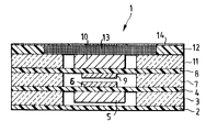
- the single figure shows a cross section through a coupling point of the switching matrix.
- the switching matrix consists of a large number of coupling points 1, preferably arranged in a matrix, for the sake of clarity, only one coupling point 1 is shown in cross section in FIG.
- a mechanically flexible film 2 preferably serves as the base of the switching matrix.
- a mechanically stable film 3 is applied to the mechanically flexible film 2.
- the two films 2, 3 can be glued together or finally laminated with the other films.
- the mechanically stable film 3 is opened in the area of the coupling points 1. This can be done, for example, by punching out or other methods known in film technology.
- a mechanically flexible film 4 is applied to the mechanically stable film 3, on the underside of which permanent magnets 5 are attached in the area of the coupling points 1 and on the upper side contact surfaces 6.
- the permanent magnets 5 and the contact surfaces 6 are preferably attached by gluing to the mechanically flexible film 4.
- the dimensions of the permanent magnet 5 are somewhat smaller than the cavities created by the opening of the mechanically stable film 3.
- a mechanically stable film 7 is applied to the mechanically flexible film 4 and is open in the area of the coupling points 1.
- the mechanically stable film 7 is basically constructed in exactly the same way as the mechanically stable film 3.
- a mechanically flexible film 8 is applied to the mechanically stable film 7, on the underside of which in the area of the coupling points 1 contact surfaces 9 and on the upper side of which a ferromagnetic material 10 are fastened.
- the contact surfaces 9 and the ferromagnetic material 10 are preferably attached by gluing.
- the contact surfaces 6, 9 are arranged congruently to one another, it being possible in principle that a plurality of contact surfaces 6, 9 are used instead of one.
- a mechanically stable film 11 is applied to the mechanically flexible film 8 and is open in the area of the coupling points 1.
- the mechanically stable film 11 is constructed in exactly the same way as the mechanically stable films 3, 7 described above.
- the height dimension of the ferromagnetic material 10 can be less than or equal to the height dimension of the mechanically stable film 11.
- On the mechanically stable Foil 11 is a preferably mechanically stable foil 12 applied.
- Coils 13 are embedded or etched into the film 12 in the area of the coupling points.
- the electrical leads 14 of the coils 13 are arranged on the film 12, preferably in a matrix, towards the edges of the switching matrix.
- the function of the switching matrix is explained below. If the coil 13 of a coupling point 1 is selectively excited with appropriate polarity, a magnetic field is built up which magnetizes the ferromagnetic material 10. This results in a magnetic attraction between the permanent magnet and the ferromagnetic material 10. The mechanically flexible foils 4, 8 are bent by the force to such an extent that the contact surfaces 6, 9 touch and switch through the coupling point. If the excitation of the coil 13 is now interrupted, the ferromagnetic material 10 remains in its magnetized state and the coupling point 1 remains switched through. If the contact is to be separated again, the coil 13 is excited with reverse polarity.
- the electrical signal lines, which are connected or disconnected via the contact surfaces 6, 9, are preferably led out as conductor tracks on the mechanically flexible foils 4, 8 to the edges of the switching matrix.
- the distances between the individual coupling points 1 must be selected to be sufficiently large that, on the one hand, magnetic interference is avoided and, on the other hand, the mechanically flexible foils 4, 8 are sufficiently clamped in the region of a coupling point 1 so that the foils 4, 8 deflect the surrounding coupling points 1 at a coupling point 1 are not influenced.
- the individual foils can be glued or laminated together, for example.
- the production by means of foils, which can be processed, for example, from the roll, enables particularly cost-effective production with high throughput.
- a preferred field of application of the switching matrix is the use as a signal-independent, remotely controllable distributor in communication and data technology.
Landscapes
- Physics & Mathematics (AREA)
- Electromagnetism (AREA)
- Micromachines (AREA)
- Use Of Switch Circuits For Exchanges And Methods Of Control Of Multiplex Exchanges (AREA)
- Near-Field Transmission Systems (AREA)
- Push-Button Switches (AREA)
- Non-Reversible Transmitting Devices (AREA)
- Control Of Stepping Motors (AREA)
- Inorganic Insulating Materials (AREA)
- Control Of Eletrric Generators (AREA)
- Electronic Switches (AREA)
Priority Applications (1)
| Application Number | Priority Date | Filing Date | Title |
|---|---|---|---|
| BR9710461A BR9710461A (pt) | 1996-07-30 | 1997-07-09 | Processo para a preparacÆo de espumas de pol¡uretano espumas de poliuretano semi-r¡gidas de c-lula aberta e composicÆo reativa a isocianato |
Applications Claiming Priority (2)
| Application Number | Priority Date | Filing Date | Title |
|---|---|---|---|
| DE19529974A DE19529974C1 (de) | 1995-08-16 | 1995-08-16 | Koppelfeld |
| DE19529974 | 1995-08-16 |
Publications (3)
| Publication Number | Publication Date |
|---|---|
| EP0758792A2 true EP0758792A2 (fr) | 1997-02-19 |
| EP0758792A3 EP0758792A3 (fr) | 1998-05-13 |
| EP0758792B1 EP0758792B1 (fr) | 2001-10-17 |
Family
ID=7769515
Family Applications (1)
| Application Number | Title | Priority Date | Filing Date |
|---|---|---|---|
| EP96112250A Expired - Lifetime EP0758792B1 (fr) | 1995-08-16 | 1996-07-30 | Réseau de connexion |
Country Status (12)
| Country | Link |
|---|---|
| US (1) | US5742012A (fr) |
| EP (1) | EP0758792B1 (fr) |
| JP (1) | JPH09120746A (fr) |
| CN (1) | CN1148256A (fr) |
| AT (1) | ATE207237T1 (fr) |
| BR (1) | BR9603444A (fr) |
| CA (1) | CA2182931C (fr) |
| DE (2) | DE19529974C1 (fr) |
| DK (1) | DK0758792T3 (fr) |
| ES (1) | ES2166852T3 (fr) |
| MX (1) | MX9603441A (fr) |
| PT (1) | PT758792E (fr) |
Families Citing this family (7)
| Publication number | Priority date | Publication date | Assignee | Title |
|---|---|---|---|---|
| US5921382A (en) * | 1998-09-30 | 1999-07-13 | Datahand Systems, Inc | Magnetically enhanced membrane switch |
| US6410360B1 (en) * | 1999-01-26 | 2002-06-25 | Teledyne Industries, Inc. | Laminate-based apparatus and method of fabrication |
| US6366186B1 (en) * | 2000-01-20 | 2002-04-02 | Jds Uniphase Inc. | Mems magnetically actuated switches and associated switching arrays |
| AUPQ824700A0 (en) | 2000-06-20 | 2000-07-13 | Alcatel | Bi-stable microswitch including magnetic latch |
| US20020075108A1 (en) * | 2000-12-15 | 2002-06-20 | Ward Lester G. | Method of remotely actuating a membrane switch by attractive or repulsive magnetic force |
| AU784864B2 (en) * | 2001-03-15 | 2006-07-13 | Micro Relay Holdings Pty Ltd | Telecommunication relay array for DSL network configuration |
| BE1021760B1 (nl) * | 2013-09-26 | 2016-01-15 | Niko Nv | Elektromechanisch relais |
Family Cites Families (9)
| Publication number | Priority date | Publication date | Assignee | Title |
|---|---|---|---|---|
| US3869687A (en) * | 1972-12-07 | 1975-03-04 | Int Standard Electric Corp | Bistable crosspoint matrix |
| DE2633201A1 (de) * | 1976-07-23 | 1978-01-26 | Siemens Ag | Gleichrichterkoppler |
| JPS58169825A (ja) * | 1982-03-31 | 1983-10-06 | 日本メクトロン株式会社 | パネルキ−ボ−ド |
| DE3334708A1 (de) * | 1983-09-24 | 1985-04-11 | Preh, Elektrofeinmechanische Werke Jakob Preh Nachf. Gmbh & Co, 8740 Bad Neustadt | Folientastatur |
| US5121091A (en) * | 1989-09-08 | 1992-06-09 | Matsushita Electric Industrial Co., Ltd. | Panel switch |
| SE468693B (sv) * | 1991-06-17 | 1993-03-01 | Ericsson Telefon Ab L M | Galvanisk kopplingsanordning |
| US5616897A (en) * | 1993-06-30 | 1997-04-01 | Weber; Michael R. | Flexible keyboard |
| US5561278A (en) * | 1994-09-16 | 1996-10-01 | Rutten; Phillip | Membrane switch |
| US5557079A (en) * | 1995-07-03 | 1996-09-17 | Motorola, Inc. | Electronic device with shielded keypad interface |
-
1995
- 1995-08-16 DE DE19529974A patent/DE19529974C1/de not_active Expired - Fee Related
-
1996
- 1996-07-30 AT AT96112250T patent/ATE207237T1/de not_active IP Right Cessation
- 1996-07-30 PT PT96112250T patent/PT758792E/pt unknown
- 1996-07-30 DE DE59607931T patent/DE59607931D1/de not_active Expired - Fee Related
- 1996-07-30 EP EP96112250A patent/EP0758792B1/fr not_active Expired - Lifetime
- 1996-07-30 ES ES96112250T patent/ES2166852T3/es not_active Expired - Lifetime
- 1996-07-30 DK DK96112250T patent/DK0758792T3/da active
- 1996-08-08 CA CA002182931A patent/CA2182931C/fr not_active Expired - Fee Related
- 1996-08-15 JP JP8215622A patent/JPH09120746A/ja active Pending
- 1996-08-15 BR BR9603444A patent/BR9603444A/pt not_active Application Discontinuation
- 1996-08-16 MX MX9603441A patent/MX9603441A/es not_active IP Right Cessation
- 1996-08-16 CN CN96111517A patent/CN1148256A/zh active Pending
- 1996-09-03 US US08/707,131 patent/US5742012A/en not_active Expired - Lifetime
Also Published As
| Publication number | Publication date |
|---|---|
| DE19529974C1 (de) | 1996-10-24 |
| CA2182931C (fr) | 2002-06-25 |
| JPH09120746A (ja) | 1997-05-06 |
| PT758792E (pt) | 2002-04-29 |
| ATE207237T1 (de) | 2001-11-15 |
| ES2166852T3 (es) | 2002-05-01 |
| CA2182931A1 (fr) | 1997-02-17 |
| EP0758792A3 (fr) | 1998-05-13 |
| BR9603444A (pt) | 1998-05-12 |
| EP0758792B1 (fr) | 2001-10-17 |
| MX9603441A (es) | 1997-03-29 |
| CN1148256A (zh) | 1997-04-23 |
| US5742012A (en) | 1998-04-21 |
| DE59607931D1 (de) | 2001-11-22 |
| DK0758792T3 (da) | 2002-02-04 |
Similar Documents
| Publication | Publication Date | Title |
|---|---|---|
| DE60016692T2 (de) | Nicht-flüchtigen MEMS mikro-relais mit magnetischen Betätigern | |
| DE3884937T2 (de) | Digitalisiertafel. | |
| EP0712267B1 (fr) | Installation de commande modulaire avec connexion sur bus secteur intégré | |
| DE10393867B4 (de) | Mehrschicht-Berührungsanzeigegerät auf Grundlage elektromagnetischer Stellglieder | |
| WO2010034820A1 (fr) | Antenne pour balise rfid | |
| EP1080503B1 (fr) | Capteur piezoelectrique de flexion et module constitue d'une pluralite de capteurs piezoelectriques de flexion | |
| EP0758792B1 (fr) | Réseau de connexion | |
| CH633385A5 (de) | Piezoelektrische schaltvorrichtung. | |
| DE602004001989T2 (de) | Elektromagnetisches relais | |
| DE102016216330A1 (de) | Flexible Spulenordnung für einen magnetoelektrischen Weggeber, Weggeber und Herstellungsverfahren | |
| EP2230486B1 (fr) | Capteur de position | |
| DE102023131529A1 (de) | Statormodul und Planarantriebssystem | |
| EP0494436A2 (fr) | Dispositif d'essai | |
| DE10043549C1 (de) | Mikroschalter und Verfahren zu dessen Herstellung | |
| EP2071293B1 (fr) | Capteur de position | |
| DE1962951A1 (de) | Einstellbares Daempfungsglied | |
| DE69905233T2 (de) | Elektrostatisch gesteuertes Mikrorelais | |
| EP0888707B1 (fr) | Module avec ensemble de circuits | |
| EP2048782B1 (fr) | Dispositif de commutation actionnable pour un véhicule automobile | |
| DE10323765B4 (de) | Elektrisches Bauteil und Verwendung eines elektrisch leitenden, magnetischen Pulvers | |
| DE10062400C2 (de) | Flexible Induktive Bauelemente für Leiterfolien | |
| DE10349100A1 (de) | Vorrichtung zur Darstellung taktiler Zeichen und graphischer Elemente | |
| EP1835552A1 (fr) | Dispositif piézoélectrique | |
| DE4117136C1 (fr) | ||
| DE102009058835A1 (de) | Sensorspule |
Legal Events
| Date | Code | Title | Description |
|---|---|---|---|
| PUAI | Public reference made under article 153(3) epc to a published international application that has entered the european phase |
Free format text: ORIGINAL CODE: 0009012 |
|
| AK | Designated contracting states |
Kind code of ref document: A2 Designated state(s): AT BE CH DE DK ES FI FR GB GR IE IT LI NL PT SE |
|
| PUAL | Search report despatched |
Free format text: ORIGINAL CODE: 0009013 |
|
| AK | Designated contracting states |
Kind code of ref document: A3 Designated state(s): AT BE CH DE DK ES FI FR GB GR IE IT LI NL PT SE |
|
| 17P | Request for examination filed |
Effective date: 19980411 |
|
| 17Q | First examination report despatched |
Effective date: 19991214 |
|
| RAP1 | Party data changed (applicant data changed or rights of an application transferred) |
Owner name: KRONE GMBH |
|
| GRAG | Despatch of communication of intention to grant |
Free format text: ORIGINAL CODE: EPIDOS AGRA |
|
| GRAG | Despatch of communication of intention to grant |
Free format text: ORIGINAL CODE: EPIDOS AGRA |
|
| GRAH | Despatch of communication of intention to grant a patent |
Free format text: ORIGINAL CODE: EPIDOS IGRA |
|
| GRAH | Despatch of communication of intention to grant a patent |
Free format text: ORIGINAL CODE: EPIDOS IGRA |
|
| GRAA | (expected) grant |
Free format text: ORIGINAL CODE: 0009210 |
|
| AK | Designated contracting states |
Kind code of ref document: B1 Designated state(s): AT BE CH DE DK ES FI FR GB GR IE IT LI NL PT SE |
|
| REF | Corresponds to: |
Ref document number: 207237 Country of ref document: AT Date of ref document: 20011115 Kind code of ref document: T |
|
| REG | Reference to a national code |
Ref country code: CH Ref legal event code: NV Representative=s name: MICHELI & CIE INGENIEURS-CONSEILS Ref country code: CH Ref legal event code: EP |
|
| REG | Reference to a national code |
Ref country code: IE Ref legal event code: FG4D Free format text: GERMAN |
|
| REF | Corresponds to: |
Ref document number: 59607931 Country of ref document: DE Date of ref document: 20011122 |
|
| REG | Reference to a national code |
Ref country code: GB Ref legal event code: IF02 |
|
| REG | Reference to a national code |
Ref country code: DK Ref legal event code: T3 |
|
| GBT | Gb: translation of ep patent filed (gb section 77(6)(a)/1977) |
Effective date: 20020116 |
|
| ET | Fr: translation filed | ||
| REG | Reference to a national code |
Ref country code: PT Ref legal event code: SC4A Free format text: AVAILABILITY OF NATIONAL TRANSLATION Effective date: 20020115 |
|
| REG | Reference to a national code |
Ref country code: ES Ref legal event code: FG2A Ref document number: 2166852 Country of ref document: ES Kind code of ref document: T3 |
|
| REG | Reference to a national code |
Ref country code: GR Ref legal event code: EP Ref document number: 20020400158 Country of ref document: GR |
|
| PGFP | Annual fee paid to national office [announced via postgrant information from national office to epo] |
Ref country code: PT Payment date: 20020626 Year of fee payment: 7 |
|
| PGFP | Annual fee paid to national office [announced via postgrant information from national office to epo] |
Ref country code: FR Payment date: 20020723 Year of fee payment: 7 Ref country code: AT Payment date: 20020723 Year of fee payment: 7 |
|
| PGFP | Annual fee paid to national office [announced via postgrant information from national office to epo] |
Ref country code: BE Payment date: 20020724 Year of fee payment: 7 |
|
| PGFP | Annual fee paid to national office [announced via postgrant information from national office to epo] |
Ref country code: NL Payment date: 20020725 Year of fee payment: 7 Ref country code: ES Payment date: 20020725 Year of fee payment: 7 Ref country code: CH Payment date: 20020725 Year of fee payment: 7 |
|
| PGFP | Annual fee paid to national office [announced via postgrant information from national office to epo] |
Ref country code: GR Payment date: 20020730 Year of fee payment: 7 |
|
| PGFP | Annual fee paid to national office [announced via postgrant information from national office to epo] |
Ref country code: DE Payment date: 20020731 Year of fee payment: 7 |
|
| PLBE | No opposition filed within time limit |
Free format text: ORIGINAL CODE: 0009261 |
|
| STAA | Information on the status of an ep patent application or granted ep patent |
Free format text: STATUS: NO OPPOSITION FILED WITHIN TIME LIMIT |
|
| 26N | No opposition filed | ||
| PG25 | Lapsed in a contracting state [announced via postgrant information from national office to epo] |
Ref country code: AT Free format text: LAPSE BECAUSE OF NON-PAYMENT OF DUE FEES Effective date: 20030730 |
|
| PG25 | Lapsed in a contracting state [announced via postgrant information from national office to epo] |
Ref country code: LI Free format text: LAPSE BECAUSE OF NON-PAYMENT OF DUE FEES Effective date: 20030731 Ref country code: ES Free format text: LAPSE BECAUSE OF NON-PAYMENT OF DUE FEES Effective date: 20030731 Ref country code: CH Free format text: LAPSE BECAUSE OF NON-PAYMENT OF DUE FEES Effective date: 20030731 Ref country code: BE Free format text: LAPSE BECAUSE OF NON-PAYMENT OF DUE FEES Effective date: 20030731 |
|
| BERE | Be: lapsed |
Owner name: *KRONE G.M.B.H. Effective date: 20030731 |
|
| PG25 | Lapsed in a contracting state [announced via postgrant information from national office to epo] |
Ref country code: PT Free format text: LAPSE BECAUSE OF NON-PAYMENT OF DUE FEES Effective date: 20040131 |
|
| PG25 | Lapsed in a contracting state [announced via postgrant information from national office to epo] |
Ref country code: NL Free format text: LAPSE BECAUSE OF NON-PAYMENT OF DUE FEES Effective date: 20040201 |
|
| PG25 | Lapsed in a contracting state [announced via postgrant information from national office to epo] |
Ref country code: DE Free format text: LAPSE BECAUSE OF NON-PAYMENT OF DUE FEES Effective date: 20040203 |
|
| PG25 | Lapsed in a contracting state [announced via postgrant information from national office to epo] |
Ref country code: GR Free format text: LAPSE BECAUSE OF NON-PAYMENT OF DUE FEES Effective date: 20040205 |
|
| REG | Reference to a national code |
Ref country code: CH Ref legal event code: PL |
|
| PG25 | Lapsed in a contracting state [announced via postgrant information from national office to epo] |
Ref country code: FR Free format text: LAPSE BECAUSE OF NON-PAYMENT OF DUE FEES Effective date: 20040331 |
|
| NLV4 | Nl: lapsed or anulled due to non-payment of the annual fee |
Effective date: 20040201 |
|
| REG | Reference to a national code |
Ref country code: FR Ref legal event code: ST Ref country code: PT Ref legal event code: MM4A Free format text: LAPSE DUE TO NON-PAYMENT OF FEES Effective date: 20040131 |
|
| PGFP | Annual fee paid to national office [announced via postgrant information from national office to epo] |
Ref country code: GB Payment date: 20040716 Year of fee payment: 9 |
|
| PGFP | Annual fee paid to national office [announced via postgrant information from national office to epo] |
Ref country code: FI Payment date: 20040722 Year of fee payment: 9 |
|
| PGFP | Annual fee paid to national office [announced via postgrant information from national office to epo] |
Ref country code: SE Payment date: 20040723 Year of fee payment: 9 |
|
| PGFP | Annual fee paid to national office [announced via postgrant information from national office to epo] |
Ref country code: DK Payment date: 20040727 Year of fee payment: 9 |
|
| PGFP | Annual fee paid to national office [announced via postgrant information from national office to epo] |
Ref country code: IE Payment date: 20040729 Year of fee payment: 9 |
|
| REG | Reference to a national code |
Ref country code: ES Ref legal event code: FD2A Effective date: 20030731 |
|
| PG25 | Lapsed in a contracting state [announced via postgrant information from national office to epo] |
Ref country code: FI Free format text: LAPSE BECAUSE OF NON-PAYMENT OF DUE FEES Effective date: 20050710 |
|
| PG25 | Lapsed in a contracting state [announced via postgrant information from national office to epo] |
Ref country code: IT Free format text: LAPSE BECAUSE OF NON-PAYMENT OF DUE FEES Effective date: 20050730 Ref country code: GB Free format text: LAPSE BECAUSE OF NON-PAYMENT OF DUE FEES Effective date: 20050730 |
|
| PG25 | Lapsed in a contracting state [announced via postgrant information from national office to epo] |
Ref country code: SE Free format text: LAPSE BECAUSE OF NON-PAYMENT OF DUE FEES Effective date: 20050731 |
|
| PG25 | Lapsed in a contracting state [announced via postgrant information from national office to epo] |
Ref country code: IE Free format text: LAPSE BECAUSE OF NON-PAYMENT OF DUE FEES Effective date: 20050801 Ref country code: DK Free format text: LAPSE BECAUSE OF NON-PAYMENT OF DUE FEES Effective date: 20050801 |
|
| EUG | Se: european patent has lapsed | ||
| GBPC | Gb: european patent ceased through non-payment of renewal fee |
Effective date: 20050730 |
|
| REG | Reference to a national code |
Ref country code: DK Ref legal event code: EBP |
|
| REG | Reference to a national code |
Ref country code: IE Ref legal event code: MM4A |