EP0758809A2 - Canalisation de paroi pour installation électrique - Google Patents
Canalisation de paroi pour installation électrique Download PDFInfo
- Publication number
- EP0758809A2 EP0758809A2 EP96111888A EP96111888A EP0758809A2 EP 0758809 A2 EP0758809 A2 EP 0758809A2 EP 96111888 A EP96111888 A EP 96111888A EP 96111888 A EP96111888 A EP 96111888A EP 0758809 A2 EP0758809 A2 EP 0758809A2
- Authority
- EP
- European Patent Office
- Prior art keywords
- duct
- wall
- parapet
- front wall
- spacer
- Prior art date
- Legal status (The legal status is an assumption and is not a legal conclusion. Google has not performed a legal analysis and makes no representation as to the accuracy of the status listed.)
- Granted
Links
- 238000010616 electrical installation Methods 0.000 title claims description 17
- 125000006850 spacer group Chemical group 0.000 claims description 22
- 238000009434 installation Methods 0.000 claims description 7
- 238000005192 partition Methods 0.000 claims description 4
- 229910000831 Steel Inorganic materials 0.000 claims description 3
- 239000010959 steel Substances 0.000 claims description 3
- 210000000481 breast Anatomy 0.000 abstract 1
- 239000002775 capsule Substances 0.000 abstract 1
- 238000004873 anchoring Methods 0.000 description 1
- 238000004140 cleaning Methods 0.000 description 1
- 238000010276 construction Methods 0.000 description 1
- 239000002184 metal Substances 0.000 description 1
Images
Classifications
-
- H—ELECTRICITY
- H02—GENERATION; CONVERSION OR DISTRIBUTION OF ELECTRIC POWER
- H02G—INSTALLATION OF ELECTRIC CABLES OR LINES, OR OF COMBINED OPTICAL AND ELECTRIC CABLES OR LINES
- H02G3/00—Installations of electric cables or lines or protective tubing therefor in or on buildings, equivalent structures or vehicles
- H02G3/02—Details
- H02G3/04—Protective tubing or conduits, e.g. cable ladders or cable troughs
- H02G3/0431—Wall trunking
Definitions
- the invention relates to parapet ducts for electrical installation with a duct lower part, which is to be fastened under a window parapet to a building wall and has at least one T-shaped groove on the inside, in which partitions, mounting boxes and / or electrical installation devices can be anchored, with a detachable duct upper part and with at least one spacer, which keeps the upper and lower part of the channel at a distance such that a gap remains through which electrical connecting lines can be led to the electrical installation devices inside the parapet duct, according to the preamble of claim 1.
- Parapet ducts are electrical installation ducts that are installed on building walls immediately below the window parapet. They have a lower part that is dowelled directly to the wall and has at least one T-shaped groove on the inside of the rear wall, in which partitions, mounting elements or electrical installation devices can be anchored. Depending on requirements, power lines, low-voltage lines and data lines are laid in the duct and wired with the appropriate electrical installation devices - sockets, light switches, data interfaces, fuses, etc. The electrical installation devices are positioned at the locations corresponding to the respective workplace. After completing the electrical installation, a suitable upper part of the duct is placed on the lower part of the duct.
- the installation devices are usually directly accessible on the front of the parapet duct. Therefore the parapet channels must be mounted higher than that Tops of furnishings. However, if the window parapets do not allow such a high level of assembly, the furnishings must be placed at a sufficient distance from the parapet channels, which means that space is lost.
- parapet ducts In addition to parapet ducts in which the installation devices are accessible from the outside, there are also parapet ducts in which the installation devices are installed completely inside the lower part of the duct and the upper part of the duct has a completely smooth front. Spacer plates between the upper and lower part of the duct ensure that there is a sufficient gap between the two through which, for example, electrical connection lines can be led. When fully assembled, these parapet ducts offer an aesthetic sight. However, if, for example, the cleaning lady wants to clean the office in the evening, she has to pull off the upper part of the duct to connect the vacuum cleaner. This is extremely unsatisfactory.
- the present invention has for its object to further develop a parapet duct of the generic type in such a way that electrical installation devices are accessible even without prior removal of the upper part of the duct and that the removal and fitting of the upper part of the duct is also possible with furnishings that are immediately approaching.
- the upper part of the duct can be plugged onto the lower part of the duct, so that the space required for the pivoting movement is completely eliminated, that the electrical installation devices installed in the spacers designed according to the invention are easily accessible even without removing the upper part of the duct and that thanks to the continuous second T-slot, the spacers can be fixed in any position that is optimal for the accessibility of the installation devices.
- the shaft and / or head of the anchor pin are dimensioned such that they have metallic contact with the wall parts of the second T-slot. In this way, the equipotential bonding required for electrical safety can be produced without additional measures.
- an opening is made in the lower bar of the spacer, through which the T-head of the closure element can be passed. This allows the closure element to be easily mounted on the spacer.
- the spacer is advantageously made of sheet steel.
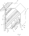
- a parapet duct consisting of a duct lower part 10, a duct upper part 20 and a spacer 30, is mounted underneath the window parapet 2 and directly adjacent to it.
- the lower channel part 10 consists essentially of a rear wall 11, a bottom wall 13 and a front wall 14.
- a rail On the inside of the rear wall 11, a rail is provided with a T-shaped groove 15 in which partitions, mounting boxes and / or electrical installation devices can be anchored.
- a second rail with a T-shaped groove 16 is provided on the front wall 14.
- the upper channel part 20 is plugged onto the lower channel part 10 vertically from above.
- This consists of a front wall 21 and a top wall 22 and a plug-in device 23 for plugging onto the upper edge 12 of the rear wall 11 of the lower channel part 10, which is slightly cranked for this purpose.
- an angle bar 25 is fastened in such a way that an open groove is created. Thanks to the angle strip 25 and the holding device 23, the upper channel part 20 can be plugged onto the lower channel part 10 vertically from above and without pivoting movement.
- a spacer mat 30 is inserted into the second T-groove 16 and fixed by means of a closure element 37 in the form of a rotary toggle with a T-shaped head.
- the lower channel part 10, the spacer plate 30 and the upper channel part 20 are matched to one another such that the angle bar 25 overlaps the spacer 30 and results in a sufficiently stable holder.
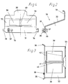
- the spacer 30 is an approximately Z-shaped sheet metal, for example steel sheet, with a lower bar 31, an upper bar 33 and a web 32.
- the web 32 has, for example, two openings 39 into which electrical installation devices (not shown) can be inserted in this way that they are accessible from below through the gap between the front wall 14 of the lower duct part and the lower edge 24 of the upper duct part 20 when the parapet duct is completely assembled (FIG. 1).
- the spacer 30 has a central web 40, which enables the installation of two simple devices. Due to the special shape 41, the central web 40 can be easily broken out without the breaking point having to be reworked, since the breaking point lies outside the area occupied by the built-in device.
- an anchor pin 36 with a T-shaped head and, on the other hand, a simple adjustment pin 35 are formed on the lower bar 31 of the spacer 30, on the one hand.
- the dimensions of these two pins 35, 36 are matched to the second T-slot 16 in such a way that a metallic and sufficiently low-resistance electrical contact is created, so that when the spacer 30 is inserted into the T-slot 16 without additional measures for electrical safety necessary equipotential bonding is established. This speeds up work on the construction site and reduces costs.
- a closure element 37 in the form of a rotary knob with a T-shaped head 38 is provided.
- An opening 34 which is matched to the head 38, enables the closure element 37 to be inserted.
- the anchoring in the T-slot 16 takes place by rotating the closure element 37, 38 at any position that is optimal for the respective application.
Landscapes
- Architecture (AREA)
- Civil Engineering (AREA)
- Structural Engineering (AREA)
- Engineering & Computer Science (AREA)
- Details Of Indoor Wiring (AREA)
- Installation Of Indoor Wiring (AREA)
- Respiratory Apparatuses And Protective Means (AREA)
- Supports For Pipes And Cables (AREA)
- Percussion Or Vibration Massage (AREA)
- Finger-Pressure Massage (AREA)
- Threshing Machine Elements (AREA)
- Window Of Vehicle (AREA)
- Coupling Device And Connection With Printed Circuit (AREA)
Applications Claiming Priority (2)
| Application Number | Priority Date | Filing Date | Title |
|---|---|---|---|
| DE29512882U DE29512882U1 (de) | 1995-08-10 | 1995-08-10 | Brüstungskanal für die Elektroinstallation |
| DE29512882U | 1995-08-10 |
Publications (3)
| Publication Number | Publication Date |
|---|---|
| EP0758809A2 true EP0758809A2 (fr) | 1997-02-19 |
| EP0758809A3 EP0758809A3 (fr) | 1998-11-25 |
| EP0758809B1 EP0758809B1 (fr) | 2002-01-16 |
Family
ID=8011623
Family Applications (1)
| Application Number | Title | Priority Date | Filing Date |
|---|---|---|---|
| EP96111888A Expired - Lifetime EP0758809B1 (fr) | 1995-08-10 | 1996-07-24 | Canalisation de paroi pour installation électrique |
Country Status (6)
| Country | Link |
|---|---|
| EP (1) | EP0758809B1 (fr) |
| AT (1) | ATE212154T1 (fr) |
| DE (2) | DE29512882U1 (fr) |
| DK (1) | DK0758809T3 (fr) |
| ES (1) | ES2169778T3 (fr) |
| NO (1) | NO963063L (fr) |
Families Citing this family (2)
| Publication number | Priority date | Publication date | Assignee | Title |
|---|---|---|---|---|
| DE29703649U1 (de) * | 1997-02-28 | 1998-07-02 | Nowa-Plast GmbH Elektrotechnische Fabrik, 35799 Merenberg | Mehrteiliges Kabelkanalsystem |
| DE202011107398U1 (de) | 2011-11-02 | 2013-02-04 | Tehalit Gmbh | Bodenkanalsystem zur Leitungsführung und zum Geräteeinbau |
Family Cites Families (2)
| Publication number | Priority date | Publication date | Assignee | Title |
|---|---|---|---|---|
| US4720768A (en) * | 1986-12-05 | 1988-01-19 | Ernst Schindele | Electrical medical rail system |
| DE9004774U1 (de) * | 1990-04-27 | 1991-08-29 | Albert Ackermann GmbH & Co KG, 5270 Gummersbach | Wandinstallationskanal |
-
1995
- 1995-08-10 DE DE29512882U patent/DE29512882U1/de not_active Expired - Lifetime
-
1996
- 1996-07-23 NO NO963063A patent/NO963063L/no not_active Application Discontinuation
- 1996-07-24 EP EP96111888A patent/EP0758809B1/fr not_active Expired - Lifetime
- 1996-07-24 AT AT96111888T patent/ATE212154T1/de not_active IP Right Cessation
- 1996-07-24 DK DK96111888T patent/DK0758809T3/da active
- 1996-07-24 ES ES96111888T patent/ES2169778T3/es not_active Expired - Lifetime
- 1996-07-24 DE DE59608586T patent/DE59608586D1/de not_active Expired - Fee Related
Non-Patent Citations (1)
| Title |
|---|
| None |
Also Published As
| Publication number | Publication date |
|---|---|
| DE59608586D1 (de) | 2002-02-21 |
| ATE212154T1 (de) | 2002-02-15 |
| NO963063L (no) | 1997-02-11 |
| ES2169778T3 (es) | 2002-07-16 |
| EP0758809A3 (fr) | 1998-11-25 |
| DE29512882U1 (de) | 1995-10-12 |
| NO963063D0 (no) | 1996-07-23 |
| DK0758809T3 (da) | 2002-05-06 |
| EP0758809B1 (fr) | 2002-01-16 |
Similar Documents
| Publication | Publication Date | Title |
|---|---|---|
| EP2100352B1 (fr) | Dispositif d'armoire de commande | |
| DE69801988T2 (de) | Rahmen für elektrische verdrahtung | |
| EP2100354B1 (fr) | Dispositif d'armoire de commande | |
| EP0872000B1 (fr) | Jeu de barres omnibus pour installation de commutation basse tension | |
| DE69111001T2 (de) | Leistungsverteilerstruktur. | |
| DE4436147C2 (de) | Geräteeinbaudose für Installationskanäle | |
| EP0872001B1 (fr) | Element enfichable pour installation de commutation basse tension | |
| EP0758809B1 (fr) | Canalisation de paroi pour installation électrique | |
| DE2850779C2 (de) | Türzarge zur Führung von elektrischen Leitern | |
| DE2043699A1 (de) | Anordnung zum Einbau von Einbauplatten in Schaltanlagen | |
| EP0926790B1 (fr) | Adaptateur avec un boîtier de base pour un jeu de barres omnibus avec plusieurs barres de distribution de courant | |
| DE3878187T2 (de) | Modulare elektrische niederspannungsschalttafel fuer ein modulares elektrisches geraet. | |
| DE19949508B4 (de) | Vorrichtung zur Befestigung von Schirmklemmen | |
| DE69901629T2 (de) | Tragkonsole für Leitungskanäle, insbesondere für elektrische Schaltschränke | |
| DE69115367T2 (de) | Verbindungskiste für eine Kabelkanaleinrichtung | |
| EP0498402B1 (fr) | Couverture pour une prise électrique ou une combinaison de prises électriques | |
| DE102004054173B4 (de) | Niederspannungsschaltschrank | |
| EP1251613B1 (fr) | Dispositif de connnection pour tableau électrique comportant des appareils extractibles | |
| DE2846948C2 (de) | Flächenkabelrost | |
| EP0678951B1 (fr) | Profil de protection contre les contacts accidentels pour une barre omnibus | |
| EP0062937A1 (fr) | Armoire de commutation électrique | |
| DE69202391T2 (de) | Kanal für Drähte und Kabel zur Verlegung auf dem Boden. | |
| EP1232509B1 (fr) | Disjoncteur basse tension comportant un boitier presentant une paroi avant et une paroi arriere | |
| EP0952649A1 (fr) | Armoire de distribution avec boîtier intérieur pour blindage HF | |
| DE2946621C2 (de) | Arbeitstisch mit einem wenigstens eine elektrische Anschlußvorrichtung enthaltenden Kanal |
Legal Events
| Date | Code | Title | Description |
|---|---|---|---|
| PUAI | Public reference made under article 153(3) epc to a published international application that has entered the european phase |
Free format text: ORIGINAL CODE: 0009012 |
|
| AK | Designated contracting states |
Kind code of ref document: A2 Designated state(s): AT BE CH DE DK ES FI FR GB IT LI NL SE |
|
| PUAL | Search report despatched |
Free format text: ORIGINAL CODE: 0009013 |
|
| AK | Designated contracting states |
Kind code of ref document: A3 Designated state(s): AT BE CH DE DK ES FI FR GB IT LI NL SE |
|
| 17P | Request for examination filed |
Effective date: 19990118 |
|
| GRAG | Despatch of communication of intention to grant |
Free format text: ORIGINAL CODE: EPIDOS AGRA |
|
| 17Q | First examination report despatched |
Effective date: 20010426 |
|
| RAP1 | Party data changed (applicant data changed or rights of an application transferred) |
Owner name: TEHALIT GMBH & CO. KG |
|
| GRAG | Despatch of communication of intention to grant |
Free format text: ORIGINAL CODE: EPIDOS AGRA |
|
| GRAH | Despatch of communication of intention to grant a patent |
Free format text: ORIGINAL CODE: EPIDOS IGRA |
|
| GRAH | Despatch of communication of intention to grant a patent |
Free format text: ORIGINAL CODE: EPIDOS IGRA |
|
| GRAA | (expected) grant |
Free format text: ORIGINAL CODE: 0009210 |
|
| REG | Reference to a national code |
Ref country code: GB Ref legal event code: IF02 |
|
| AK | Designated contracting states |
Kind code of ref document: B1 Designated state(s): AT BE CH DE DK ES FI FR GB IT LI NL SE |
|
| REF | Corresponds to: |
Ref document number: 212154 Country of ref document: AT Date of ref document: 20020215 Kind code of ref document: T |
|
| REG | Reference to a national code |
Ref country code: CH Ref legal event code: EP |
|
| REF | Corresponds to: |
Ref document number: 59608586 Country of ref document: DE Date of ref document: 20020221 |
|
| REG | Reference to a national code |
Ref country code: CH Ref legal event code: NV Representative=s name: PATENTANWAELTE SCHAAD, BALASS, MENZL & PARTNER AG |
|
| REG | Reference to a national code |
Ref country code: DK Ref legal event code: T3 |
|
| GBT | Gb: translation of ep patent filed (gb section 77(6)(a)/1977) |
Effective date: 20020416 |
|
| ET | Fr: translation filed | ||
| REG | Reference to a national code |
Ref country code: ES Ref legal event code: FG2A Ref document number: 2169778 Country of ref document: ES Kind code of ref document: T3 |
|
| PLBE | No opposition filed within time limit |
Free format text: ORIGINAL CODE: 0009261 |
|
| STAA | Information on the status of an ep patent application or granted ep patent |
Free format text: STATUS: NO OPPOSITION FILED WITHIN TIME LIMIT |
|
| 26N | No opposition filed | ||
| PGFP | Annual fee paid to national office [announced via postgrant information from national office to epo] |
Ref country code: GB Payment date: 20030630 Year of fee payment: 8 |
|
| PGFP | Annual fee paid to national office [announced via postgrant information from national office to epo] |
Ref country code: DE Payment date: 20030711 Year of fee payment: 8 |
|
| PGFP | Annual fee paid to national office [announced via postgrant information from national office to epo] |
Ref country code: NL Payment date: 20030721 Year of fee payment: 8 Ref country code: FR Payment date: 20030721 Year of fee payment: 8 |
|
| PGFP | Annual fee paid to national office [announced via postgrant information from national office to epo] |
Ref country code: AT Payment date: 20030725 Year of fee payment: 8 |
|
| PGFP | Annual fee paid to national office [announced via postgrant information from national office to epo] |
Ref country code: SE Payment date: 20030728 Year of fee payment: 8 Ref country code: FI Payment date: 20030728 Year of fee payment: 8 Ref country code: ES Payment date: 20030728 Year of fee payment: 8 Ref country code: CH Payment date: 20030728 Year of fee payment: 8 |
|
| PGFP | Annual fee paid to national office [announced via postgrant information from national office to epo] |
Ref country code: DK Payment date: 20030729 Year of fee payment: 8 Ref country code: BE Payment date: 20030729 Year of fee payment: 8 |
|
| PG25 | Lapsed in a contracting state [announced via postgrant information from national office to epo] |
Ref country code: GB Free format text: LAPSE BECAUSE OF NON-PAYMENT OF DUE FEES Effective date: 20040724 Ref country code: FI Free format text: LAPSE BECAUSE OF NON-PAYMENT OF DUE FEES Effective date: 20040724 Ref country code: AT Free format text: LAPSE BECAUSE OF NON-PAYMENT OF DUE FEES Effective date: 20040724 |
|
| PG25 | Lapsed in a contracting state [announced via postgrant information from national office to epo] |
Ref country code: SE Free format text: LAPSE BECAUSE OF NON-PAYMENT OF DUE FEES Effective date: 20040725 |
|
| PG25 | Lapsed in a contracting state [announced via postgrant information from national office to epo] |
Ref country code: ES Free format text: LAPSE BECAUSE OF NON-PAYMENT OF DUE FEES Effective date: 20040726 |
|
| PG25 | Lapsed in a contracting state [announced via postgrant information from national office to epo] |
Ref country code: LI Free format text: LAPSE BECAUSE OF NON-PAYMENT OF DUE FEES Effective date: 20040731 Ref country code: CH Free format text: LAPSE BECAUSE OF NON-PAYMENT OF DUE FEES Effective date: 20040731 Ref country code: BE Free format text: LAPSE BECAUSE OF NON-PAYMENT OF DUE FEES Effective date: 20040731 |
|
| PG25 | Lapsed in a contracting state [announced via postgrant information from national office to epo] |
Ref country code: DK Free format text: LAPSE BECAUSE OF NON-PAYMENT OF DUE FEES Effective date: 20040802 |
|
| BERE | Be: lapsed |
Owner name: *TEHALIT G.M.B.H. & CO. K.G. Effective date: 20040731 |
|
| PG25 | Lapsed in a contracting state [announced via postgrant information from national office to epo] |
Ref country code: NL Free format text: LAPSE BECAUSE OF NON-PAYMENT OF DUE FEES Effective date: 20050201 Ref country code: DE Free format text: LAPSE BECAUSE OF NON-PAYMENT OF DUE FEES Effective date: 20050201 |
|
| EUG | Se: european patent has lapsed | ||
| REG | Reference to a national code |
Ref country code: DK Ref legal event code: EBP |
|
| REG | Reference to a national code |
Ref country code: CH Ref legal event code: PL |
|
| GBPC | Gb: european patent ceased through non-payment of renewal fee |
Effective date: 20040724 |
|
| PG25 | Lapsed in a contracting state [announced via postgrant information from national office to epo] |
Ref country code: FR Free format text: LAPSE BECAUSE OF NON-PAYMENT OF DUE FEES Effective date: 20050331 |
|
| NLV4 | Nl: lapsed or anulled due to non-payment of the annual fee |
Effective date: 20050201 |
|
| REG | Reference to a national code |
Ref country code: FR Ref legal event code: ST |
|
| PG25 | Lapsed in a contracting state [announced via postgrant information from national office to epo] |
Ref country code: IT Free format text: LAPSE BECAUSE OF NON-PAYMENT OF DUE FEES;WARNING: LAPSES OF ITALIAN PATENTS WITH EFFECTIVE DATE BEFORE 2007 MAY HAVE OCCURRED AT ANY TIME BEFORE 2007. THE CORRECT EFFECTIVE DATE MAY BE DIFFERENT FROM THE ONE RECORDED. Effective date: 20050724 |
|
| REG | Reference to a national code |
Ref country code: ES Ref legal event code: FD2A Effective date: 20040726 |
|
| BERE | Be: lapsed |
Owner name: *TEHALIT G.M.B.H. & CO. K.G. Effective date: 20040731 |