EP0758909B1 - Absperrhahnventil - Google Patents
Absperrhahnventil Download PDFInfo
- Publication number
- EP0758909B1 EP0758909B1 EP95916439A EP95916439A EP0758909B1 EP 0758909 B1 EP0758909 B1 EP 0758909B1 EP 95916439 A EP95916439 A EP 95916439A EP 95916439 A EP95916439 A EP 95916439A EP 0758909 B1 EP0758909 B1 EP 0758909B1
- Authority
- EP
- European Patent Office
- Prior art keywords
- valve
- fluid flow
- stem
- valve body
- valve stem
- Prior art date
- Legal status (The legal status is an assumption and is not a legal conclusion. Google has not performed a legal analysis and makes no representation as to the accuracy of the status listed.)
- Expired - Lifetime
Links
Images


Classifications
-
- F—MECHANICAL ENGINEERING; LIGHTING; HEATING; WEAPONS; BLASTING
- F16—ENGINEERING ELEMENTS AND UNITS; GENERAL MEASURES FOR PRODUCING AND MAINTAINING EFFECTIVE FUNCTIONING OF MACHINES OR INSTALLATIONS; THERMAL INSULATION IN GENERAL
- F16K—VALVES; TAPS; COCKS; ACTUATING-FLOATS; DEVICES FOR VENTING OR AERATING
- F16K11/00—Multiple-way valves, e.g. mixing valves; Pipe fittings incorporating such valves
- F16K11/02—Multiple-way valves, e.g. mixing valves; Pipe fittings incorporating such valves with all movable sealing faces moving as one unit
- F16K11/08—Multiple-way valves, e.g. mixing valves; Pipe fittings incorporating such valves with all movable sealing faces moving as one unit comprising only taps or cocks
- F16K11/085—Multiple-way valves, e.g. mixing valves; Pipe fittings incorporating such valves with all movable sealing faces moving as one unit comprising only taps or cocks with cylindrical plug
- F16K11/0853—Multiple-way valves, e.g. mixing valves; Pipe fittings incorporating such valves with all movable sealing faces moving as one unit comprising only taps or cocks with cylindrical plug having all the connecting conduits situated in a single plane perpendicular to the axis of the plug
-
- A—HUMAN NECESSITIES
- A61—MEDICAL OR VETERINARY SCIENCE; HYGIENE
- A61M—DEVICES FOR INTRODUCING MEDIA INTO, OR ONTO, THE BODY; DEVICES FOR TRANSDUCING BODY MEDIA OR FOR TAKING MEDIA FROM THE BODY; DEVICES FOR PRODUCING OR ENDING SLEEP OR STUPOR
- A61M39/00—Tubes, tube connectors, tube couplings, valves, access sites or the like, specially adapted for medical use
- A61M39/22—Valves or arrangement of valves
- A61M39/223—Multiway valves
-
- A—HUMAN NECESSITIES
- A61—MEDICAL OR VETERINARY SCIENCE; HYGIENE
- A61M—DEVICES FOR INTRODUCING MEDIA INTO, OR ONTO, THE BODY; DEVICES FOR TRANSDUCING BODY MEDIA OR FOR TAKING MEDIA FROM THE BODY; DEVICES FOR PRODUCING OR ENDING SLEEP OR STUPOR
- A61M39/00—Tubes, tube connectors, tube couplings, valves, access sites or the like, specially adapted for medical use
- A61M39/10—Tube connectors; Tube couplings
- A61M39/16—Tube connectors; Tube couplings having provision for disinfection or sterilisation
-
- A—HUMAN NECESSITIES
- A61—MEDICAL OR VETERINARY SCIENCE; HYGIENE
- A61M—DEVICES FOR INTRODUCING MEDIA INTO, OR ONTO, THE BODY; DEVICES FOR TRANSDUCING BODY MEDIA OR FOR TAKING MEDIA FROM THE BODY; DEVICES FOR PRODUCING OR ENDING SLEEP OR STUPOR
- A61M5/00—Devices for bringing media into the body in a subcutaneous, intra-vascular or intramuscular way; Accessories therefor, e.g. filling or cleaning devices, arm-rests
- A61M5/50—Devices for bringing media into the body in a subcutaneous, intra-vascular or intramuscular way; Accessories therefor, e.g. filling or cleaning devices, arm-rests having means for preventing re-use, or for indicating if defective, used, tampered with or unsterile
- A61M5/5086—Devices for bringing media into the body in a subcutaneous, intra-vascular or intramuscular way; Accessories therefor, e.g. filling or cleaning devices, arm-rests having means for preventing re-use, or for indicating if defective, used, tampered with or unsterile for indicating if defective, used, tampered with or unsterile
-
- Y—GENERAL TAGGING OF NEW TECHNOLOGICAL DEVELOPMENTS; GENERAL TAGGING OF CROSS-SECTIONAL TECHNOLOGIES SPANNING OVER SEVERAL SECTIONS OF THE IPC; TECHNICAL SUBJECTS COVERED BY FORMER USPC CROSS-REFERENCE ART COLLECTIONS [XRACs] AND DIGESTS
- Y10—TECHNICAL SUBJECTS COVERED BY FORMER USPC
- Y10T—TECHNICAL SUBJECTS COVERED BY FORMER US CLASSIFICATION
- Y10T137/00—Fluid handling
- Y10T137/8593—Systems
- Y10T137/86493—Multi-way valve unit
- Y10T137/86815—Multiple inlet with single outlet
- Y10T137/86823—Rotary valve
Definitions
- This invention relates generally to stop-cock valves used with fluid delivery sets. More specifically, this invention relates to a stop-cock valve having an improved anti-free flow design which can be sterilized by gas sterilization methods.
- Such fluid delivery systems typically include one or more flexible plastic tubes connected to one or more containers of fluid to be administered to the patient.
- a stop-cock valve which allows switching from one fluid container to another.
- Such valves normally employ a rotatable stem which allows the operator thereof to choose which fluid container is placed in fluid flow communication with the patient by rotation of the stem relative to the valve (see e.g. FR-A-2 286 325).
- valves One of the primary difficulties with this type of valve is that it is not always apparent to the operator which fluid flow container is in fluid flow communication with the patient. Also, in the particular instance where the operator is preparing the fluid delivery set for initial use with a patient, it is often difficult to ensure that the valve has remained closed in order to prevent accidental premature free-flow of fluid during preparation of the delivery set.
- Another common difficulty with stop-cock valves of this type is that of ensuring that complete sterilization of the fluid flow channels within the rotating stem thereof occurs during gas sterilization. Since an open gas flow passage must be available through the stem in order to ensure proper gas sterilization of the internal flow passages therethrough, it is necessary to be able to ensure that the rotating stem is always in the proper position to allow free-flow of gas therethrough when the valve is being sterilized.
- a stop-cock type valve which allows for simple and immediate visual and/or tactile indication of the position of the rotatable stem in the valve.
- a stop-cock valve which ensures that the rotatable stem thereof remains in the closed position prior to initial use in order to avoid accidental free flow of fluid therethrough during setup.
- a stop-cock valve which is gas sterilizeable with complete assurance that the sterilizing gas has access to the flow passages within the rotating stem.
- a valve which never allows fluid flow connection to occur between inlet ports, regardless of the position of the valve stem thereof so as to prevent intermixing of solutions in the fluid containers which may be attached to the inlet ports.
- the valve includes a valve body having at least one inlet port therein adapted to be attached through tubing to a fluid container and at least one outlet port adapted to be attached through tubing to a patient, a rotatable valve stem formed with fluid flow passages which are positioned to interconnect with the inlet and outlet ports in the valve body upon rotation thereof, and a valve handle integrally formed with the stem usable by the operator for rotating the stem to the desired position.
- the handle is uniquely shaped to give tactile and visual input to the operator as to its position relative to the valve body and the open fluid flow path through the valve, whereby the valve also includes a shear-away interference member which interferes with initial attempted rotation of the rotatable stem relative to the valve body to prevent accidental premature rotation of the stem prior to its intended initial use so that premature free flow of fluid through the valve cannot occur.
- the shear-away interference member can be overcome by the operator upon the operator's initial intentional rotation of the valve stem by exertion of an elevated rotational force which operates to destroy the interference member which thereafter does not inhibit rotation of the rotatable stem.
- the invention also includes a sterilization passage which connects one of the ports of the valve body directly with the fluid flow passages within the rotatable stem whenever the rotatable stem is in its completely closed position.
- a sterilization passage which connects one of the ports of the valve body directly with the fluid flow passages within the rotatable stem whenever the rotatable stem is in its completely closed position.
- an embodiment of a stop-cock valve made in accordance with the principles of the present invention referred to generally by the reference numeral 10, is provided for regulating fluid flow through a fluid delivery set such as may be designed for enteral feeding of a patient.
- valve 10 includes a valve body 11 and a handle 12.
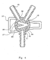
- the handle 12 is integrally formed with a rotatable stem 13 which is held within a cavity 17 of the body 11 by the snap fit attachment of an annular rib 18 of the stem 13 into an annular detent 19 adjacent the open end of the body cavity 17.
- a slightly beveled entrance section 20 in the body cavity 17 assists in forming the snap fit between the stem 13 and the body 11.
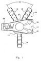
- the body 11 includes a male outlet port 14 and a pair of male inlet ports 15 and 16 which are designed to be attachable to tubular members in a well known manner to place the valve in fluid flow connection with one or more fluid containers (not shown) and a patient to whom the fluid is to be delivered.
- Each of the ports 14, 15 and 16 lie in a single plane, and each includes a longitudinal axis which intersect at the center of the body cavity 17 and which are perpendicular to the longitudinal axis about which the body 11 and stem 13 rotate relative to each other.
- the longitudinal axes of the male inlet ports 15 and 16 form an included angle (a) of 60°, and the axis of the male outlet port 14 is equidistant (150°) from both inlet ports 15 and 16.
- the rotatable stem 13 preferably includes a V-shaped or Y-shaped fluid flow passage 21 comprising a first arm 22 and a second arm 23 which have a convergence at 24.
- the preferred embodiment of valve 10 incorporates at least three operational positions of the rotatable stem 13 relative to the body 11.
- a first or “closed” operating position is shown in Figure 1 and Figure 4.
- all outlets of the fluid flow passage 21 through the stem 13 are positioned adjacent the body cavity 17 of the body 11.
- the rotatable stem 13 prevents fluid flow from either inlet port 15 or 16 from passing therethrough into the outlet port 14.
- the top surface 25 of the handle 12 includes markings 26 which may be in the form of words and/or directional arrows which indicate the direction of flow through the valve 10. As is evident in Figure 1, the markings 26 indicate that the handle 12 (and similarly the stem 13) is not positioned in any manner such that fluid can flow from either inlet port 15 or 16 to the outlet port 14.
- Figure 5 shows the rotatable stem 13 rotated 60° from its position in Figure 4. This is the second operating position of the valve 10, and allows fluid flow from inlet port 16 through the second arm 23 of the fluid flow passage 21 into the outlet port 14.
- Figure 6 shows the rotatable stem 13 rotated a distance of 60° from its position shown in Figure 5. This is the third operational position of the valve 10 which allows fluid flow from inlet port 15 through the first arm 22 of the fluid flow passage 21 into the outlet port 14.
- the rotatable stem 13 may include a shear-away interference member 29 positioned below the fluid flow passage 21.
- the shear-away interference member 29 is positioned adjacent the bottom surface 30 of the cavity 17.
- a rigid protrusion 31 may also be integrally formed with the body 11 to extend above the bottom surface 30 of the cavity 17 so as to be located in an interference position with the shear-away interference member 29.
- the shear-away interference member 29 is positioned relative to the rigid protrusion 31 so as to be interfering with relative rotation of the stem 13 and the body 11.
- the shear-away interference member 29 is positioned so that the initial rotation of the stem 13 from the "closed” position cannot be accomplished without intentionally shearing the shear-away interference member 29 away from the stem 13 with the rigid protrusion 31. Shearing of the shear-away interference member 29 requires a significantly higher rotational force to be exerted on the stem 13 before initial rotation out of the "closed” position can occur.
- the shear-away interference member 29 substantially inhibits accidental initial rotation of the stem 13 and thereby ensures that the valve 10 remains in its original "closed” position at all times subsequent to its initial assembly, even through sterilization, packaging, and setup procedures, until first use of the valve 10 as a part of a fluid delivery set occurs.
- the positions of the shear-away member 29 and the rigid protrusion 31 may be reversed on the stem 13 and body bottom surface 30 if desired with substantially the same operative result.
- a sterilization passage 32 is also positioned in the rotatable stem 13 so that fluid flow communication can exist between the fluid flow passage 21 and the inlet port 15 to assist in sterilization of the valve 10.
- the sterilization passage 32 allows sterilization gas to pass through inlet port 15 into the fluid flow passage 21 to ensure complete sterilization of the valve 10.
- a second preferred embodiment of the valve 10 of the present invention may include a valve body 11' which has only one inlet port 15.
- the valve body 11' as shown in Figure 10 operates in an identical manner as the body 11 as shown in Figures 1-9 except that of course no flow through the valve 10 occurs until the rotatable stem 13 is rotated to place fluid flow passage 21 in fluid flow alignment with the single open inlet port 15.
- the valve body 11' shown in Figure 10 is modified to include only one inlet port 15, the rotatable stem 13 may nevertheless be constructed in an identical manner as described above with respect to the first preferred embodiment of the invention as shown in Figures 1-9.
- either inlet port 15 or 16 may be formed as the single inlet port of the second preferred embodiment of the valve 10. The invention is not intended to be limited to a single position of the inlet port, even though only inlet port 15 is shown in Figure 10.
Landscapes
- Engineering & Computer Science (AREA)
- Health & Medical Sciences (AREA)
- Heart & Thoracic Surgery (AREA)
- General Engineering & Computer Science (AREA)
- Animal Behavior & Ethology (AREA)
- General Health & Medical Sciences (AREA)
- Anesthesiology (AREA)
- Biomedical Technology (AREA)
- Hematology (AREA)
- Life Sciences & Earth Sciences (AREA)
- Mechanical Engineering (AREA)
- Pulmonology (AREA)
- Public Health (AREA)
- Veterinary Medicine (AREA)
- Infusion, Injection, And Reservoir Apparatuses (AREA)
- Taps Or Cocks (AREA)
- Valve Housings (AREA)
- Mechanically-Actuated Valves (AREA)
- Control Of Combustion (AREA)
- Magnetically Actuated Valves (AREA)
Claims (12)
- Ein Ventil (10) umfassend:Einen Ventilkörper (11), der mindestens eine Einlassöffnung (15,16) und mindestens eine Auslassöffnung (14) hat;
einen Ventilschaft (13), der mindestens teilweise innerhalb des Ventilkörpers (11) positioniert ist und einen Griff (12) umfasst, wobei der Ventilschaft (13) mindestens einen Fluidflussdurchlass (21) durch diesen umfasst, wobei der Ventilschaft (13) relativ zu dem Ventilkörper (11) zwischen einer ersten Position, in welcher der Fluidfluss zwischen der mindestens einen Einlassöffnung (15) und der mindestens einen Auslassöffnung (14) unterbunden ist, und einer zweiten Position, in welcher der mindestens eine Fluidflussdurchlass (21) die mindestens eine Einlassöffnung (16) mit der mindestens einen Auslassöffnung (14) zwecks Fluidfluss durch diese verbindet, drehbar ist, dadurch gekennzeichnet, dass das Ventil (10) ferner mindestens ein Drehbehinderungsteil (29) umfasst, um im Wesentlichen die anfängliche relative Drehung zwischen dem Ventilschaft (13) und dem Ventilkörper (11) zwischen der ersten Position und der zweiten Position zu behindern, und das Drehbehinderungsteil (29) umfasst einen starren Vorsprung (31) der sich entweder von dem Ventilkörper (11) oder von dem Ventilschaft (13) erstreckt und ein abscherbares Behinderungsteil (29) welches sich vom Anderen des genannten Ventilkörpers (11) oder des genannten Ventilschaftes (13) erstreckt, wobei der starre Vorsprung (31) und das abscherbare Behinderungsteil (29) auf dem Ventilkörper (11) und dem Ventilschaft (13) derart positioniert sind, dass das abscherbare Behinderungsteil (29) und der starre Vorsprung (31) einander berühren und die anfängliche Drehung des Ventilschaftes (13) relativ zu dem Ventilkörper (11) zwischen der ersten Position und der zweiten Position behindern. - Das Ventil (10) gemäss Anspruch 1, wobei das abscherbare Drehbehinderungsteil (29) von seiner Befestigung an dem Ventilkörper (11) oder an dem Ventilschaft (13) durch den starren Vorsprung (31) abgelöst wird, wenn eine Drehkraft, die auf den Ventilschaft (13) relativ zu dem Ventilkörper (11) ausgeübt wird, um den Ventilschaft (13) von der ersten Position zu der zweiten Position zu verschieben, einen vorgegebenen Wert überschreitet.
- Das Ventil (10) gemäss Anspruch 2, wobei der vorgegebene Kraftwert, der benötigt wird, um das abscherbare Behinderungsteil (29) während der anfänglichen Bewegung des Ventilschaftes (13) relativ zu dem Ventilkörper (11) von der ersten Position zu der zweiten Position abzulösen, signifikant grösser ist als der Wert der Drehkraft, der benötigt wird um anschliessend den Ventilschaft (13) relativ zu dem Ventilkörper (11) von der ersten Position zu der zweiten Position zu bewegen, nachdem das abscherbare Behinderungsteil (29) abgelöst worden ist.
- Das Ventil (10) gemäss einem der vorangehenden Ansprüche, wobei der mindestens eine Fluidflussdurchlass (21) durch den Ventilschaft (13) einen V-förmigen Fluidflussdurchlass umfasst, der einen ersten Arm (22) und einen zweiten Arm (23) hat, welche in einem einzigen Fluidflussweg zusammenlaufen.
- Das Ventil (10) gemäss einem der vorangehenden Ansprüche, wobei die mindestens eine Einlassöffnung (15,16) zwei Einlassöffnungen (15,16) umfasst und die zwei Einlassöffnungen (15,16) und die mindestens eine Auslassöffnung (14) in einer einzigen Ebene liegen.
- Das Ventil (10) gemäss einem der vorangehenden Ansprüche, wobei der Ventilkörper (11) und der Ventilschaft (13) Schulterteile (27,28) umfassen, welche die Drehung des Ventilkörpers (11) relativ zu dem Ventilschaft (13) um einen Winkel von nur 120° oder weniger erlauben.
- Das Ventil (10) gemäss einem der vorangehenden Ansprüche, wobei der Griff (12) auf diesem geformte Markierungen (26) umfasst, um den Weg des Fluidflusses durch das Ventil (10) zu kennzeichnen.
- Das Ventil (10) gemäss einem der vorangehenden Ansprüche umfassend:Mindestens einen in dem Ventilschaft (13) derart geformten Entlüftungsdurchlass (32), dass die mindestens eine Einlassöffnung (15,16) und der mindestens eine Fluidflussdurchlass (21) in Fluidflussverbindung stehen, wenn der Ventilschaft (13) in der ersten Position relativ zu dem Ventilkörper (11) ist.
- Das Ventil gemäss einem der vorangehenden Ansprüche, wobei die mindestens eine Einlassöffnung (15, 16) zwei Einlassöffnungen (15,16) umfasst, die zwei Einlassöffnungen (15,16) und die mindestens eine Auslassöffnung (14) in einer einzigen Ebene liegen und die zwei Einlassöffnungen (15,16) weisen einen Winkelabstand von 60° voneinander auf.
- Das Ventil (10) gemäss einem der vorangehenden Ansprüche umfassend: Einen Ventilkörper (11), der mindestens zwei Einlassöffnungen (15,16) hat; der Fluidflussdurchlass (21) hat einen ersten Arm (22) und einen zweiten Arm (23), welche in einem einzigen Fluidflussweg zusammenlaufen, der Ventilschaft (13) ist drehbar relativ zu dem Ventilkörper (11) zwischen der ersten Position, in welcher der Fluidfluss zwischen den mindestens zwei Einlassöffnungen (15,16) und der mindestens einen Auslassöffnung (14) unterbunden ist, der zweiten Position, in welcher der zweite Arm (23) des Fluidflussdurchlasses eine der mindestens zwei Einlassöffnungen (15,16) mit der mindestens einen Auslassöffnung (14) zwecks Flüssigkeitsfluss durch diese, verbindet, und einer dritten Position in welcher der erste Arm (22) des Fluidflussdurchlasses (21) die Andere der mindestens zwei Einlassöffnungen (15, 16) mit der mindestens einen Auslassöffnung (14) zwecks Fluidfluss durch diese, verbindet.
- Das Ventil gemäss Anspruch 10, wobei das Ventil (10) ferner Schulterteile (27,28) auf dem Ventil (10) umfasst, um eine relative Drehung des Ventilschaftes (13) und des Ventilkörpers (11), ausser zwischen den ersten, zweiten und dritten Positionen, zu verhindern, wobei die Drehung des Ventilschaftes (13) relativ zu dem Ventilkörper (11) um eine Fluidflussverbindung zwischen der einen der mindestens zwei Einlassöffnungen (15,16) und der Anderen der mindestens zwei Einlassöffnungen (15, 16) zu erlauben, verhindert ist.
- Das Ventil (10) gemäss Anspruch 10 oder 11, wobei die mindestens zwei Einlassöffnungen (15,16) und die mindestens eine Auslassöffnung (14) in einer einzigen Ebene liegen.
Priority Applications (3)
| Application Number | Priority Date | Filing Date | Title |
|---|---|---|---|
| DK02008461T DK1221322T3 (da) | 1994-04-21 | 1995-04-17 | Afspærringsventil |
| EP02008461A EP1221322B1 (de) | 1994-04-21 | 1995-04-17 | Absperrhahnventil |
| EP20020008462 EP1221323A1 (de) | 1994-04-21 | 1995-04-17 | Absperrhahnventil |
Applications Claiming Priority (3)
| Application Number | Priority Date | Filing Date | Title |
|---|---|---|---|
| US08/230,657 US5443453A (en) | 1994-04-21 | 1994-04-21 | Stop-cock valve |
| US230657 | 1994-04-21 | ||
| PCT/US1995/004728 WO1995028975A1 (en) | 1994-04-21 | 1995-04-17 | Stop-cock valve |
Related Child Applications (2)
| Application Number | Title | Priority Date | Filing Date |
|---|---|---|---|
| EP20020008462 Division EP1221323A1 (de) | 1994-04-21 | 1995-04-17 | Absperrhahnventil |
| EP02008461A Division EP1221322B1 (de) | 1994-04-21 | 1995-04-17 | Absperrhahnventil |
Publications (3)
| Publication Number | Publication Date |
|---|---|
| EP0758909A1 EP0758909A1 (de) | 1997-02-26 |
| EP0758909A4 EP0758909A4 (de) | 1998-08-12 |
| EP0758909B1 true EP0758909B1 (de) | 2002-10-16 |
Family
ID=22866081
Family Applications (3)
| Application Number | Title | Priority Date | Filing Date |
|---|---|---|---|
| EP95916439A Expired - Lifetime EP0758909B1 (de) | 1994-04-21 | 1995-04-17 | Absperrhahnventil |
| EP02008461A Expired - Lifetime EP1221322B1 (de) | 1994-04-21 | 1995-04-17 | Absperrhahnventil |
| EP20020008462 Withdrawn EP1221323A1 (de) | 1994-04-21 | 1995-04-17 | Absperrhahnventil |
Family Applications After (2)
| Application Number | Title | Priority Date | Filing Date |
|---|---|---|---|
| EP02008461A Expired - Lifetime EP1221322B1 (de) | 1994-04-21 | 1995-04-17 | Absperrhahnventil |
| EP20020008462 Withdrawn EP1221323A1 (de) | 1994-04-21 | 1995-04-17 | Absperrhahnventil |
Country Status (10)
| Country | Link |
|---|---|
| US (1) | US5443453A (de) |
| EP (3) | EP0758909B1 (de) |
| AT (2) | ATE304388T1 (de) |
| AU (1) | AU702421B2 (de) |
| CA (1) | CA2188296C (de) |
| DE (2) | DE69528582T2 (de) |
| DK (1) | DK1221322T3 (de) |
| ES (1) | ES2248437T3 (de) |
| IL (1) | IL113420A (de) |
| WO (1) | WO1995028975A1 (de) |
Cited By (1)
| Publication number | Priority date | Publication date | Assignee | Title |
|---|---|---|---|---|
| CN104747758A (zh) * | 2013-12-30 | 2015-07-01 | 浙江三花股份有限公司 | 双通截止阀 |
Families Citing this family (75)
| Publication number | Priority date | Publication date | Assignee | Title |
|---|---|---|---|---|
| US5540668A (en) * | 1995-01-20 | 1996-07-30 | Wilson, Jr.; Roland B. | Anti-cross contamination valve and fluid delivery systems using same |
| JPH08252327A (ja) * | 1995-01-30 | 1996-10-01 | Minnesota Mining & Mfg Co <3M> | 2種のカテーテルに流体を選択的に指向させるスイッチ |
| US5569208A (en) * | 1995-08-01 | 1996-10-29 | Merit Medical Systems, Inc. | System for managing delivery of contrast media |
| US5658248A (en) * | 1995-08-04 | 1997-08-19 | Localmed, Inc. | Double-blind infusion device and method |
| US5800408A (en) * | 1996-11-08 | 1998-09-01 | Micro Therapeutics, Inc. | Infusion device for distributing infusate along an elongated infusion segment |
| US5807312A (en) * | 1997-05-23 | 1998-09-15 | Dzwonkiewicz; Mark R. | Bolus pump apparatus |
| DE29715833U1 (de) * | 1997-09-04 | 1997-12-18 | Filtertek B.V., Limerick | Vorrichtung zur kontinuierlichen ambulanten Peritonealdialyse |
| US6296655B1 (en) | 1998-04-27 | 2001-10-02 | Advanced Cardiovascular Systems, Inc. | Catheter balloon with biased multiple wings |
| US6726647B1 (en) * | 1998-10-23 | 2004-04-27 | Gambro Ab | Method and device for measuring access flow |
| US6273133B1 (en) | 1999-10-15 | 2001-08-14 | Baxter International Inc. | Fluid flow rate switching device |
| US6254921B1 (en) | 1999-12-08 | 2001-07-03 | Surmodics, Inc. | Coating process and apparatus |
| US6419662B1 (en) * | 2001-01-30 | 2002-07-16 | Anthony Solazzo | Continuous irrigation Y-tubing control valve device and system |
| JP4743106B2 (ja) * | 2001-11-14 | 2011-08-10 | 株式会社ジェイ・エム・エス | 三方活栓 |
| EP1459783A4 (de) * | 2001-11-14 | 2007-04-25 | Jms Co Ltd | Dreiwege-hahn und flüssigkeitstransfusionskreislauf oder bluttransfusionskreislauf unter verwendung des dreiwege-hahns |
| EP1448252B1 (de) * | 2001-11-16 | 2007-04-18 | Medinnovation AG | Medizinische pumpvorrichtung |
| US6843070B1 (en) | 2002-02-28 | 2005-01-18 | Snap-On Technologies, Inc. | Refrigerant recycling system with single ball valve |
| US6800072B2 (en) | 2002-06-26 | 2004-10-05 | Medex, Inc. | Contrast dispensing system |
| ITMI20021895A1 (it) * | 2002-09-06 | 2004-03-07 | Gambro Lundia Ab | Organo di intercettazione di flusso. |
| USD491664S1 (en) | 2002-09-20 | 2004-06-15 | Medex, Inc. | Vented contrast media reservoir cap assembly |
| USD492779S1 (en) | 2002-09-20 | 2004-07-06 | Medex, Inc. | Vented contrast media reservoir cap |
| USD491665S1 (en) | 2002-09-20 | 2004-06-15 | Medex, Inc. | Contrast media reservoir cap |
| USD492780S1 (en) | 2002-09-20 | 2004-07-06 | Medex, Inc. | Portion of a vented contrast media reservoir |
| USD493226S1 (en) | 2002-09-20 | 2004-07-20 | Medex, Inc. | Portion of a contrast media reservoir |
| FR2845452B1 (fr) * | 2002-10-04 | 2005-09-23 | Vygon | Robinet a cle tournante indexable. |
| US20040138641A1 (en) * | 2003-01-09 | 2004-07-15 | Medex, Inc. | Contrast dispensing system with nonsticking luer connector |
| ES1056051Y (es) * | 2003-11-12 | 2004-06-01 | Amor Vicente Gomez | Valvula de tres vias perfeccionada. |
| FR2863679B1 (fr) * | 2003-12-11 | 2007-09-14 | Ge Med Sys Global Tech Co Llc | Robinet trois voies pour la distribution de fluide et son utilisation |
| US7794423B2 (en) * | 2004-05-25 | 2010-09-14 | Covidien Ag | Re-certification system for a flow control apparatus |
| US7462170B2 (en) * | 2004-05-25 | 2008-12-09 | Covidien Ag | Administration feeding set and valve mechanism |
| EP1627658B1 (de) * | 2004-08-16 | 2012-03-21 | Fresenius Kabi Deutschland GmbH | T-formiges Zweiwegventil für eine Infusionsleitung |
| US20060155247A1 (en) * | 2005-01-13 | 2006-07-13 | Lampropoulos Bryan R | Introducer sheath with rotatable stop cock |
| US7937775B2 (en) | 2005-08-09 | 2011-05-10 | Microtek Medical, Inc. | Surgical protective head gear assembly including high volume air delivery system |
| CA2623420C (en) * | 2005-09-13 | 2014-06-10 | Edwards Lifesciences Corporation | Closed blood sampling system with isolated pressure monitoring |
| US20070068584A1 (en) * | 2005-09-27 | 2007-03-29 | Murdock Douglas J | Y-manifold valve |
| US20070119508A1 (en) * | 2005-11-29 | 2007-05-31 | West Richard L | Fluid Flow Diversion Valve and Blood Collection System Employing Same |
| US8062269B2 (en) | 2006-06-09 | 2011-11-22 | Baxter International Inc. | Fail safe dual chamber peritoneal dialysis/infusion system |
| US7690396B2 (en) * | 2006-07-20 | 2010-04-06 | Baxter International Inc. | Multirate tubing flow restrictor |
| WO2008037494A1 (en) * | 2006-09-29 | 2008-04-03 | Ge Medical Systems Benelux Sa | Pressure-resistant 3-way stopcock |
| DE102007003602B4 (de) * | 2007-01-18 | 2017-11-23 | B/E Aerospace Systems Gmbh | Sauerstoffnotversorgungssystem |
| US7963951B2 (en) * | 2007-02-09 | 2011-06-21 | Tyco Healthcare Group Lp | Medical valve device |
| US20080294148A1 (en) * | 2007-05-22 | 2008-11-27 | Albert Gardner | System and method for refilling an implanted delivery device |
| WO2009035457A1 (en) * | 2007-09-13 | 2009-03-19 | Reilly Dillon | Dip coating apparatus with height adjustable coating tubes and method of coating |
| WO2009046164A1 (en) | 2007-10-05 | 2009-04-09 | Tyco Healthcare Group Lp | Seal anchor for use in surgical procedures |
| US20090143723A1 (en) * | 2007-11-29 | 2009-06-04 | Baxter International Inc. | Flow control device for peritoneal dialysis |
| USD615644S1 (en) | 2008-08-15 | 2010-05-11 | Ost Medical, Inc. | Anti-free flow modulator |
| USD738500S1 (en) | 2008-10-02 | 2015-09-08 | Covidien Lp | Seal anchor for use in surgical procedures |
| US20100228232A1 (en) * | 2009-02-18 | 2010-09-09 | Loay Salman | Catheter flushing assembly |
| DK2528558T3 (en) * | 2010-01-29 | 2015-07-13 | Mbh Internat A S | A drainage valve and a collection bag device comprising said valve |
| US8814829B2 (en) | 2010-08-12 | 2014-08-26 | Baxter International Inc. | Drug delivery device for fluid restricted patients |
| US8882732B2 (en) | 2010-11-22 | 2014-11-11 | Hollister Incorporated | Valve for ostomy pouch |
| EP2758097A4 (de) | 2011-09-21 | 2015-07-01 | Bayer Medical Care Inc | Kontinuierliche multi-fluid-pumpvorrichtung, antrieb sowie betätigungssystem und -verfahren dafür |
| US9814866B1 (en) | 2012-05-31 | 2017-11-14 | Gaurav K Goswami | Flushable drainage device and method of use |
| US9610406B2 (en) * | 2012-07-11 | 2017-04-04 | Sonofi-Aventis Deutschland GmbH | Dispense interface for an ejection device |
| PL2887912T3 (pl) * | 2012-08-23 | 2022-03-07 | Djo, Llc | Orteza z kontrolą nadmuchiwania |
| US9067009B2 (en) | 2013-01-25 | 2015-06-30 | Acist Medical Systems, Inc. | Regulating flow paths in a medical injection system |
| CN103231857A (zh) * | 2013-05-13 | 2013-08-07 | 江南大学 | 一种液体盒中袋包装 |
| US9907945B2 (en) | 2014-05-01 | 2018-03-06 | Michael D. Laufer | Medical devices and methods for fluid transfer |
| US10064649B2 (en) | 2014-07-07 | 2018-09-04 | Covidien Lp | Pleated seal for surgical hand or instrument access |
| KR101483619B1 (ko) * | 2014-09-16 | 2015-01-19 | 배동수 | 다기능 음료 선택기 및 이를 이용한 음료용 빨대 |
| US9707011B2 (en) | 2014-11-12 | 2017-07-18 | Covidien Lp | Attachments for use with a surgical access device |
| EP4628145A3 (de) | 2015-01-09 | 2025-12-03 | Bayer Healthcare LLC | System zur abgabe mehrerer flüssigkeiten mit einwegset zur mehrfachverwendung und funktionen davon |
| GB2536042B (en) * | 2015-03-05 | 2022-02-09 | Pluemat Place & Luebeck Gmbh & Co | Multiport for medical device |
| CN104721920B (zh) * | 2015-03-26 | 2018-12-21 | 江苏阳普医疗科技有限公司 | 一种输注泵的多速调节装置及其调速方法 |
| EP3589704B1 (de) | 2017-03-03 | 2025-05-14 | Harland Medical Systems, Inc. | Beschichtungszusammensetzung mit einem hydrophilen vernetzer, ein hydrophober vernetzer und gegebenenfalls ein hydrogel und verfahren zur herstellung und verwendung davon |
| US10875048B2 (en) | 2017-09-05 | 2020-12-29 | Harland Medical Systems, Inc | Coating apparatus with an automatic fluid level system, and methods of using the same |
| DK3514419T3 (da) * | 2018-01-19 | 2020-08-03 | Siemens Schweiz Ag | Ventil med en bypass-ledning |
| WO2019173704A1 (en) * | 2018-03-08 | 2019-09-12 | Loma Linda University | Apparatus, device, method, and kit for infant gavage feeding |
| CN108465131B (zh) * | 2018-03-21 | 2020-07-03 | 北京市隆福医院 | 一种双腔吸引过滤装置以及过滤方法 |
| US11541191B2 (en) * | 2019-05-09 | 2023-01-03 | Lexion Medical, Llc | Distributed flow path insufflation |
| CN110953364B (zh) * | 2019-12-20 | 2021-10-08 | 浙江博顿燃具科技有限公司 | 一种旋塞阀 |
| US11529170B2 (en) | 2020-04-29 | 2022-12-20 | Covidien Lp | Expandable surgical access port |
| JP7661487B2 (ja) * | 2020-09-23 | 2025-04-14 | ボストン サイエンティフィック メディカル デバイス リミテッド | マルチウェイコネクタ |
| US12589233B2 (en) * | 2021-09-23 | 2026-03-31 | Engineered Medical Systems, Inc. | Ball valve for use in a respiration circuit and a respiration circuit including a ball valve |
| US12453846B2 (en) | 2021-11-24 | 2025-10-28 | Boston Scientific Scimed, Inc. | Stopcock with indexing mechanism providing feedback of hub position |
| FR3163135A1 (fr) * | 2024-06-10 | 2025-12-12 | Costruzioni Elettroniche Industriali Automatismi S.P.A. C.E.I.A. S.P.A. | Vanne pour la dérivation sélective d’un produit granulaire ou d’une poudre |
Family Cites Families (42)
| Publication number | Priority date | Publication date | Assignee | Title |
|---|---|---|---|---|
| US992502A (en) * | 1910-12-23 | 1911-05-16 | Miles S Hollis | Stop-cock. |
| US1162935A (en) * | 1915-02-18 | 1915-12-07 | Walter Lange | Safety-valve. |
| US1815449A (en) * | 1929-01-30 | 1931-07-21 | Schellberg Oscar Boto | Valve mechanism for proctotherapy apparatus |
| US3048192A (en) * | 1957-08-14 | 1962-08-07 | Cordis Corp | Surgical valve |
| US3091239A (en) * | 1958-08-25 | 1963-05-28 | Moeller Wilhelm | Apparatus for intravasal injection of gaseous and liquid media |
| US3097585A (en) * | 1959-07-17 | 1963-07-16 | Speed O Print Business Machine | Photocopying devices |
| US3536451A (en) * | 1965-01-21 | 1970-10-27 | Isadore Ludwin | System for cyclic pulsed pumping and fluid interaction |
| US3774822A (en) * | 1970-03-16 | 1973-11-27 | Polytop Corp | Dispensing closure with initial breakable disc seal |
| US3678960A (en) * | 1970-06-08 | 1972-07-25 | Saul Leibinsohn | Stop cock |
| US3788599A (en) * | 1972-06-28 | 1974-01-29 | Nosco Plastics | Plug valve |
| US3834372A (en) * | 1973-01-12 | 1974-09-10 | S Turney | Disposable manifold with atmospheric vent |
| US3858601A (en) * | 1973-02-01 | 1975-01-07 | Roto Swivel Corp Inc | Movable appliance assembly and gas cut-off valve |
| US3831625A (en) * | 1973-02-20 | 1974-08-27 | D Roediger | Intravenous safety device |
| CA1027540A (en) * | 1974-04-04 | 1978-03-07 | Baxter Travenol Laboratories | Adjustable valve |
| US3985133A (en) * | 1974-05-28 | 1976-10-12 | Imed Corporation | IV pump |
| US3957082A (en) * | 1974-09-26 | 1976-05-18 | Arbrook, Inc. | Six-way stopcock |
| US3994294A (en) * | 1975-02-28 | 1976-11-30 | Ivac Corporation | Syringe pump valving and motor direction control system |
| US4219021A (en) * | 1978-02-27 | 1980-08-26 | Fink Joseph L | Multi-position stop-cock valve for intravenous administration of multiple medications |
| US4460358A (en) * | 1980-11-07 | 1984-07-17 | Ivac Corporation | Combined load and latch mechanism for fluid flow control apparatus |
| FR2526515B1 (fr) * | 1982-05-06 | 1986-03-07 | Sotralentz | Element d'inviolabilite pour robinet de recipient |
| US4470429A (en) * | 1982-05-06 | 1984-09-11 | Jandy Industries, Inc. | Three-way valve |
| US4497344A (en) * | 1982-12-06 | 1985-02-05 | Dresser Industries, Inc. | Frangible valve stem assembly for rotary valve |
| EP0131214B1 (de) * | 1983-07-06 | 1989-08-23 | IRITECNA Società per l'Impiantistica Industriale e l'Assetto del Territorio per Azioni | Verfahren und Hubbalkenofen für das Zwischenerwärmen von Rohren in Warmwalzwerken |
| US4593717A (en) * | 1983-08-12 | 1986-06-10 | Levasseur Joseph E | Valve |
| JPS60205075A (ja) * | 1984-03-28 | 1985-10-16 | Kawasaki Steel Corp | 溶融金属保持器への流体吹込み用切換弁 |
| US4557725A (en) * | 1984-05-04 | 1985-12-10 | Oximetrix, Inc. | I. V. Pump cassette |
| US4604093A (en) * | 1984-06-12 | 1986-08-05 | I-Flow Corporation | Apparatus and method for administering multiple fluid infusions |
| US5005604A (en) * | 1984-07-13 | 1991-04-09 | Aslanian Jerry L | Flow control device for administration of intravenous fluids |
| US4585442A (en) * | 1984-07-26 | 1986-04-29 | Ivy Medical, Inc. | Miniature intravenous infusion rate controller |
| US4689043A (en) * | 1986-03-19 | 1987-08-25 | Imed Corporation | IV tube activator |
| US4691895A (en) * | 1986-07-18 | 1987-09-08 | Garff Jeffrey L | Faucet handle arrangement |
| JP2772007B2 (ja) * | 1987-03-19 | 1998-07-02 | フレセニウス ユー.エス.エイ. インコーポレイテッド | 持続性自己管理腹膜透析の装置 |
| US4950230A (en) * | 1987-03-19 | 1990-08-21 | Delmed, Inc. | Method and apparatus for bagless continuous ambulatory peritoneal dialysis |
| US4794944A (en) * | 1987-10-14 | 1989-01-03 | Dresser Industries, Inc. | Plastic valve |
| US4904245A (en) * | 1988-12-07 | 1990-02-27 | Allen S. Chen | Surgical valve assembly for urinary bladder irrigation and drainage |
| US5017192A (en) * | 1989-10-20 | 1991-05-21 | Minnesota Mining And Manufacturing Company | Free flow prevention system for infusion pump |
| US5156186A (en) * | 1989-10-31 | 1992-10-20 | Manska Wayne E | Stopcock valve |
| US5046528A (en) * | 1989-10-31 | 1991-09-10 | Manska Wayne E | Stopcock valve |
| US5104387A (en) * | 1990-05-25 | 1992-04-14 | St. Jude Medical, Inc. | Bi-planar fluid control valve |
| JPH0693916B2 (ja) * | 1990-10-31 | 1994-11-24 | テルモ株式会社 | 輸液ポンプ |
| US5244463A (en) * | 1991-12-06 | 1993-09-14 | Block Medical, Inc. | Programmable infusion pump |
| US5364364A (en) * | 1993-08-04 | 1994-11-15 | Ivac Corporation | Automatic flow control valve system |
-
1994
- 1994-04-21 US US08/230,657 patent/US5443453A/en not_active Expired - Lifetime
-
1995
- 1995-04-17 DK DK02008461T patent/DK1221322T3/da active
- 1995-04-17 EP EP95916439A patent/EP0758909B1/de not_active Expired - Lifetime
- 1995-04-17 AT AT02008461T patent/ATE304388T1/de active
- 1995-04-17 EP EP02008461A patent/EP1221322B1/de not_active Expired - Lifetime
- 1995-04-17 DE DE69528582T patent/DE69528582T2/de not_active Expired - Lifetime
- 1995-04-17 ES ES02008461T patent/ES2248437T3/es not_active Expired - Lifetime
- 1995-04-17 CA CA 2188296 patent/CA2188296C/en not_active Expired - Lifetime
- 1995-04-17 AU AU22939/95A patent/AU702421B2/en not_active Expired
- 1995-04-17 WO PCT/US1995/004728 patent/WO1995028975A1/en not_active Ceased
- 1995-04-17 AT AT95916439T patent/ATE226099T1/de active
- 1995-04-17 DE DE1995634457 patent/DE69534457T8/de active Active
- 1995-04-17 EP EP20020008462 patent/EP1221323A1/de not_active Withdrawn
- 1995-04-19 IL IL11342095A patent/IL113420A/en not_active IP Right Cessation
Cited By (1)
| Publication number | Priority date | Publication date | Assignee | Title |
|---|---|---|---|---|
| CN104747758A (zh) * | 2013-12-30 | 2015-07-01 | 浙江三花股份有限公司 | 双通截止阀 |
Also Published As
| Publication number | Publication date |
|---|---|
| DE69528582T2 (de) | 2003-07-10 |
| CA2188296C (en) | 2001-10-09 |
| DE69534457T2 (de) | 2006-06-29 |
| IL113420A0 (en) | 1995-07-31 |
| DE69534457D1 (de) | 2005-10-20 |
| ATE226099T1 (de) | 2002-11-15 |
| DK1221322T3 (da) | 2005-12-19 |
| IL113420A (en) | 1998-10-30 |
| WO1995028975A1 (en) | 1995-11-02 |
| DE69528582D1 (de) | 2002-11-21 |
| EP0758909A4 (de) | 1998-08-12 |
| EP0758909A1 (de) | 1997-02-26 |
| US5443453A (en) | 1995-08-22 |
| CA2188296A1 (en) | 1995-10-22 |
| AU2293995A (en) | 1995-11-16 |
| EP1221322A1 (de) | 2002-07-10 |
| ES2248437T3 (es) | 2006-03-16 |
| EP1221323A1 (de) | 2002-07-10 |
| ATE304388T1 (de) | 2005-09-15 |
| DE69534457T8 (de) | 2006-10-19 |
| EP1221322B1 (de) | 2005-09-14 |
| AU702421B2 (en) | 1999-02-18 |
Similar Documents
| Publication | Publication Date | Title |
|---|---|---|
| EP0758909B1 (de) | Absperrhahnventil | |
| EP0812221B1 (de) | Vorrichtung zur kontrolle von biologischen/medizinischen flüssigkeitsströmen zum und vom patienten | |
| EP1789709B1 (de) | Absperrhahn | |
| CN102834140B (zh) | 用于肠内管饲应用的三向关闭旋塞 | |
| EP2298406B1 (de) | Verbinderanordnung | |
| US20110011474A1 (en) | Multi-port stopcock valve and flow designating system | |
| US12123504B2 (en) | Closed stopcock | |
| US20080067462A1 (en) | Stopcock With Swabbable Valve | |
| US10449351B2 (en) | Valve for administration of multiple drug fluids | |
| AU2003302373A1 (en) | Liquid transfusing tube and liquid transfusing tube set | |
| TW202302168A (zh) | 用於引導流體流動的系統及方法 | |
| EP4015030B1 (de) | Verbessertes tastgefühl für einen mehrstufigen absperrhahn | |
| HK1004377B (en) | Apparatus for controlling flow of biological/medical fluids to and from a patient |
Legal Events
| Date | Code | Title | Description |
|---|---|---|---|
| PUAI | Public reference made under article 153(3) epc to a published international application that has entered the european phase |
Free format text: ORIGINAL CODE: 0009012 |
|
| 17P | Request for examination filed |
Effective date: 19961120 |
|
| AK | Designated contracting states |
Kind code of ref document: A1 Designated state(s): AT BE CH DE DK ES FR GB GR IE IT LI LU NL SE |
|
| A4 | Supplementary search report drawn up and despatched | ||
| AK | Designated contracting states |
Kind code of ref document: A4 Designated state(s): AT BE CH DE DK ES FR GB GR IE IT LI LU NL SE |
|
| 17Q | First examination report despatched |
Effective date: 20001218 |
|
| RAP1 | Party data changed (applicant data changed or rights of an application transferred) |
Owner name: SHERWOOD SERVICES AG |
|
| GRAG | Despatch of communication of intention to grant |
Free format text: ORIGINAL CODE: EPIDOS AGRA |
|
| GRAG | Despatch of communication of intention to grant |
Free format text: ORIGINAL CODE: EPIDOS AGRA |
|
| GRAH | Despatch of communication of intention to grant a patent |
Free format text: ORIGINAL CODE: EPIDOS IGRA |
|
| GRAH | Despatch of communication of intention to grant a patent |
Free format text: ORIGINAL CODE: EPIDOS IGRA |
|
| GRAA | (expected) grant |
Free format text: ORIGINAL CODE: 0009210 |
|
| AK | Designated contracting states |
Kind code of ref document: B1 Designated state(s): AT BE CH DE DK ES FR GB GR IE IT LI LU NL SE |
|
| PG25 | Lapsed in a contracting state [announced via postgrant information from national office to epo] |
Ref country code: NL Free format text: LAPSE BECAUSE OF FAILURE TO SUBMIT A TRANSLATION OF THE DESCRIPTION OR TO PAY THE FEE WITHIN THE PRESCRIBED TIME-LIMIT Effective date: 20021016 Ref country code: GR Free format text: LAPSE BECAUSE OF FAILURE TO SUBMIT A TRANSLATION OF THE DESCRIPTION OR TO PAY THE FEE WITHIN THE PRESCRIBED TIME-LIMIT Effective date: 20021016 Ref country code: BE Free format text: LAPSE BECAUSE OF FAILURE TO SUBMIT A TRANSLATION OF THE DESCRIPTION OR TO PAY THE FEE WITHIN THE PRESCRIBED TIME-LIMIT Effective date: 20021016 |
|
| REF | Corresponds to: |
Ref document number: 226099 Country of ref document: AT Date of ref document: 20021115 Kind code of ref document: T |
|
| REG | Reference to a national code |
Ref country code: GB Ref legal event code: FG4D |
|
| REG | Reference to a national code |
Ref country code: CH Ref legal event code: EP |
|
| REG | Reference to a national code |
Ref country code: IE Ref legal event code: FG4D |
|
| REF | Corresponds to: |
Ref document number: 69528582 Country of ref document: DE Date of ref document: 20021121 |
|
| REG | Reference to a national code |
Ref country code: CH Ref legal event code: NV Representative=s name: E. BLUM & CO. PATENTANWAELTE |
|
| PG25 | Lapsed in a contracting state [announced via postgrant information from national office to epo] |
Ref country code: SE Free format text: LAPSE BECAUSE OF FAILURE TO SUBMIT A TRANSLATION OF THE DESCRIPTION OR TO PAY THE FEE WITHIN THE PRESCRIBED TIME-LIMIT Effective date: 20030116 Ref country code: DK Free format text: LAPSE BECAUSE OF FAILURE TO SUBMIT A TRANSLATION OF THE DESCRIPTION OR TO PAY THE FEE WITHIN THE PRESCRIBED TIME-LIMIT Effective date: 20030116 |
|
| NLV1 | Nl: lapsed or annulled due to failure to fulfill the requirements of art. 29p and 29m of the patents act | ||
| PGFP | Annual fee paid to national office [announced via postgrant information from national office to epo] |
Ref country code: GR Payment date: 20030424 Year of fee payment: 9 |
|
| PG25 | Lapsed in a contracting state [announced via postgrant information from national office to epo] |
Ref country code: ES Free format text: LAPSE BECAUSE OF FAILURE TO SUBMIT A TRANSLATION OF THE DESCRIPTION OR TO PAY THE FEE WITHIN THE PRESCRIBED TIME-LIMIT Effective date: 20030429 |
|
| ET | Fr: translation filed | ||
| PLBE | No opposition filed within time limit |
Free format text: ORIGINAL CODE: 0009261 |
|
| STAA | Information on the status of an ep patent application or granted ep patent |
Free format text: STATUS: NO OPPOSITION FILED WITHIN TIME LIMIT |
|
| 26N | No opposition filed |
Effective date: 20030717 |
|
| REG | Reference to a national code |
Ref country code: CH Ref legal event code: PFA Owner name: SHERWOOD SERVICES AG Free format text: SHERWOOD SERVICES AG#SCHWERTSTRASSE 9#8201 SCHAFFHAUSEN (CH) -TRANSFER TO- SHERWOOD SERVICES AG#SCHWERTSTRASSE 9#8201 SCHAFFHAUSEN (CH) |
|
| REG | Reference to a national code |
Ref country code: CH Ref legal event code: PFA Owner name: COVIDIEN AG Free format text: SHERWOOD SERVICES AG#SCHWERTSTRASSE 9#8201 SCHAFFHAUSEN (CH) -TRANSFER TO- COVIDIEN AG#VICTOR VON BRUNS-STRASSE 19#8212 NEUHAUSEN AM RHEINFALL (CH) |
|
| REG | Reference to a national code |
Ref country code: FR Ref legal event code: CD Ref country code: FR Ref legal event code: CA |
|
| PGFP | Annual fee paid to national office [announced via postgrant information from national office to epo] |
Ref country code: LU Payment date: 20140502 Year of fee payment: 20 |
|
| PGFP | Annual fee paid to national office [announced via postgrant information from national office to epo] |
Ref country code: GB Payment date: 20140428 Year of fee payment: 20 Ref country code: IE Payment date: 20140428 Year of fee payment: 20 |
|
| PGFP | Annual fee paid to national office [announced via postgrant information from national office to epo] |
Ref country code: CH Payment date: 20140428 Year of fee payment: 20 Ref country code: AT Payment date: 20140402 Year of fee payment: 20 Ref country code: DE Payment date: 20140429 Year of fee payment: 20 Ref country code: IT Payment date: 20140429 Year of fee payment: 20 Ref country code: FR Payment date: 20140417 Year of fee payment: 20 |
|
| REG | Reference to a national code |
Ref country code: DE Ref legal event code: R071 Ref document number: 69528582 Country of ref document: DE |
|
| REG | Reference to a national code |
Ref country code: CH Ref legal event code: PL |
|
| REG | Reference to a national code |
Ref country code: GB Ref legal event code: PE20 Expiry date: 20150416 |
|
| REG | Reference to a national code |
Ref country code: IE Ref legal event code: MK9A |
|
| REG | Reference to a national code |
Ref country code: AT Ref legal event code: MK07 Ref document number: 226099 Country of ref document: AT Kind code of ref document: T Effective date: 20150417 |
|
| PG25 | Lapsed in a contracting state [announced via postgrant information from national office to epo] |
Ref country code: GB Free format text: LAPSE BECAUSE OF EXPIRATION OF PROTECTION Effective date: 20150416 |
|
| PG25 | Lapsed in a contracting state [announced via postgrant information from national office to epo] |
Ref country code: IE Free format text: LAPSE BECAUSE OF EXPIRATION OF PROTECTION Effective date: 20150417 |