EP0759117B2 - Anordnung zum vortrieb eines tunnel- oder abwasserrohrs - Google Patents
Anordnung zum vortrieb eines tunnel- oder abwasserrohrs Download PDFInfo
- Publication number
- EP0759117B2 EP0759117B2 EP95915162A EP95915162A EP0759117B2 EP 0759117 B2 EP0759117 B2 EP 0759117B2 EP 95915162 A EP95915162 A EP 95915162A EP 95915162 A EP95915162 A EP 95915162A EP 0759117 B2 EP0759117 B2 EP 0759117B2
- Authority
- EP
- European Patent Office
- Prior art keywords
- pipe
- arrangement according
- thick matter
- matter pump
- pressure
- Prior art date
- Legal status (The legal status is an assumption and is not a legal conclusion. Google has not performed a legal analysis and makes no representation as to the accuracy of the status listed.)
- Expired - Lifetime
Links
- 239000004575 stone Substances 0.000 claims description 27
- 238000005520 cutting process Methods 0.000 claims description 12
- 239000000314 lubricant Substances 0.000 claims description 4
- 238000003825 pressing Methods 0.000 claims description 4
- 238000005553 drilling Methods 0.000 claims 2
- 230000000284 resting effect Effects 0.000 claims 1
- 239000000463 material Substances 0.000 description 9
- 230000005641 tunneling Effects 0.000 description 6
- 239000007788 liquid Substances 0.000 description 4
- 238000004140 cleaning Methods 0.000 description 3
- 238000000034 method Methods 0.000 description 3
- 239000002689 soil Substances 0.000 description 3
- XLYOFNOQVPJJNP-UHFFFAOYSA-N water Substances O XLYOFNOQVPJJNP-UHFFFAOYSA-N 0.000 description 3
- 238000011010 flushing procedure Methods 0.000 description 2
- 238000002347 injection Methods 0.000 description 2
- 239000007924 injection Substances 0.000 description 2
- 238000012423 maintenance Methods 0.000 description 2
- 238000004519 manufacturing process Methods 0.000 description 2
- 238000012544 monitoring process Methods 0.000 description 2
- 238000005096 rolling process Methods 0.000 description 2
- 239000010865 sewage Substances 0.000 description 2
- 239000002002 slurry Substances 0.000 description 2
- 206010010774 Constipation Diseases 0.000 description 1
- 230000006978 adaptation Effects 0.000 description 1
- 238000007906 compression Methods 0.000 description 1
- 239000000356 contaminant Substances 0.000 description 1
- 230000001419 dependent effect Effects 0.000 description 1
- 238000011161 development Methods 0.000 description 1
- 230000018109 developmental process Effects 0.000 description 1
- 238000010586 diagram Methods 0.000 description 1
- 238000005259 measurement Methods 0.000 description 1
- 238000005192 partition Methods 0.000 description 1
- JTJMJGYZQZDUJJ-UHFFFAOYSA-N phencyclidine Chemical class C1CCCCN1C1(C=2C=CC=CC=2)CCCCC1 JTJMJGYZQZDUJJ-UHFFFAOYSA-N 0.000 description 1
- 239000011435 rock Substances 0.000 description 1
- 238000012216 screening Methods 0.000 description 1
- 239000007787 solid Substances 0.000 description 1
- 239000000243 solution Substances 0.000 description 1
- 239000000725 suspension Substances 0.000 description 1
- 230000036346 tooth eruption Effects 0.000 description 1
- 238000012549 training Methods 0.000 description 1
- 239000002351 wastewater Substances 0.000 description 1
Images

Classifications
-
- E—FIXED CONSTRUCTIONS
- E21—EARTH OR ROCK DRILLING; MINING
- E21D—SHAFTS; TUNNELS; GALLERIES; LARGE UNDERGROUND CHAMBERS
- E21D9/00—Tunnels or galleries, with or without linings; Methods or apparatus for making thereof; Layout of tunnels or galleries
- E21D9/12—Devices for removing or hauling away excavated material or spoil; Working or loading platforms
- E21D9/124—Helical conveying means therefor
-
- E—FIXED CONSTRUCTIONS
- E21—EARTH OR ROCK DRILLING; MINING
- E21B—EARTH OR ROCK DRILLING; OBTAINING OIL, GAS, WATER, SOLUBLE OR MELTABLE MATERIALS OR A SLURRY OF MINERALS FROM WELLS
- E21B7/00—Special methods or apparatus for drilling
- E21B7/20—Driving or forcing casings or pipes into boreholes, e.g. sinking; Simultaneously drilling and casing boreholes
- E21B7/208—Driving or forcing casings or pipes into boreholes, e.g. sinking; Simultaneously drilling and casing boreholes using down-hole drives
-
- E—FIXED CONSTRUCTIONS
- E21—EARTH OR ROCK DRILLING; MINING
- E21D—SHAFTS; TUNNELS; GALLERIES; LARGE UNDERGROUND CHAMBERS
- E21D9/00—Tunnels or galleries, with or without linings; Methods or apparatus for making thereof; Layout of tunnels or galleries
- E21D9/005—Tunnels or galleries, with or without linings; Methods or apparatus for making thereof; Layout of tunnels or galleries by forcing prefabricated elements through the ground, e.g. by pushing lining from an access pit
-
- E—FIXED CONSTRUCTIONS
- E21—EARTH OR ROCK DRILLING; MINING
- E21D—SHAFTS; TUNNELS; GALLERIES; LARGE UNDERGROUND CHAMBERS
- E21D9/00—Tunnels or galleries, with or without linings; Methods or apparatus for making thereof; Layout of tunnels or galleries
- E21D9/12—Devices for removing or hauling away excavated material or spoil; Working or loading platforms
- E21D9/13—Devices for removing or hauling away excavated material or spoil; Working or loading platforms using hydraulic or pneumatic conveying means
Definitions
- the invention relates to an arrangement for propulsion a tunnel or sewage pipe in the preamble of claim 1 specified version.
- the Discharge via wagons and rails is easy, but quite time-consuming, because the head only then can work when the lorry is on site. With gritty-grainy Soil, but also with hard rock, will promote flushing applied.
- the flows Carrier liquid or suspension at high speed through the cutting space of the head and carries about 15% of the circulating volume with overburden.
- the carrier liquid becomes above ground via cyclones and filters etc. separated from the overburden and flows into the cycle back to.
- This method is time-consuming bulky and not suitable for all floors. at very soft, fine-grained, for example loam or clayey soils has the attitude of earth pressure proven problematic.
- the invention has for its object a Arrangement of the type specified above to improve that even on floors with soft plastic and liquid consistency Avoidance of overburden breakthrough and earth pressure the head can be kept constant.
- the solution according to the invention is based on the Thoughts out on the exit side of the with the Cutting area of the transport pipe connected to the head to build up a back pressure that also with soft plastic overburden adapted to the advance First pressure maintenance enabled.
- the outlet-side end of the transport pipe one behind the other a pressure-tight lockable stone trap and the suction side of a slurry pump can be closed in a pressure-tight manner can be connected and that the thick matter pump pressure side with a successively extendable delivery line is connected for the overburden, the thick matter pump as a hydraulically operated piston pump is designed with one or two delivery cylinders, whose delivery cylinder can be closed in a pressure-tight manner
- Material feed container opens or ends in which one connected to the delivery line, alternately connectable to the delivery cylinder or cylinders Pipe slide engages.
- the pressure-tight training the overburden transport route to the suction side of the Thick matter pump enables the given propulsion Adaptation of the counter pressure to earth pressure, and regardless of the consistency of the overburden.
- the Thick matter pump can have an additional overpressure for the removal of the overburden through the conveyor line provide.
- the thick matter pump is expedient in that against the head of the pipe mounted.
- the thick matter pump and its preferably hydraulic drive units on one Interface separable and in two neighboring Pipe pieces can be assembled.
- the transport tube of the jacking head an elastic or articulated bendable compensator to connect with the thick matter pump.
- the stone trap is rigid at the exit end of the transport pipe flanged while the compensator between the stone trap and the suction side of the Thick matter pump is arranged.
- Pressure monitoring can be carried out along the Overburden transport route at least two intervening in this Pressure sensors are arranged. Earth pressure monitoring takes place advantageously by a pressure sensor engaging in the cutting area. Two additional pressure sensors can be used immediately be placed in front of and behind the stone trap. at Exceeding a predetermined pressure drop along the stone trap can indicate the presence of a Stopfers are closed, making an interruption of tunneling for the purpose of cleaning the stone trap makes necessary.
- An advantageous embodiment of the invention stipulates that the stone trap with a pressure-tight a removable cover that can be closed on the entry side to the delivery pipe and on the outlet side to the suction side the pot connected to the thick matter pump arranged screen grid, the solid, such Stones or root pieces of a certain size, which could lead to a blockage of the delivery line, restrains.
- the stone trap can also be used as a cross slide trained, in passage opening tapering and / or containing a screen Have passage channel for the overburden channel. In case of cleaning the cross slide is moved so that the passage channel from the outside for cleaning purposes is accessible.
- a counterweight on the free side of the pipe section arranged for mass balance.
- a lubricant injection to be provided in the delivery line.
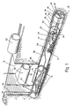
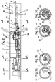
- the tunnel boring machine shown in the drawing is for the production of micro tunnels and small tunnels determines which tunnel or Wastewater pipes using the pipe compression process (pipe Jacking) from a starting shaft 10 with the help of a hydraulically actuated press slide 12 in a tunneling section 14 are introduced.
- pipe compression process pipe Jacking
- the head 16 essentially consists from a cylindrical shield jacket 18, one of the Shield jacket delimiting on the face, motorized driven, equipped with cutting teeth 20 Scraper disc 22 and one with a motor driven Conveyor screw 24 equipped on the entry side engaging in the cutting space 26 of the head 16, through the partition 28 of the cutting space rearward reaching transport pipe 30 for the spoil 32 accumulating in the cutting space 26.
- Am exit end of the transport tube 30 is a can be closed in a pressure-tight manner by means of a cover 34 Flanged stone trap 36, the outlet port 38 via a flexible compensator 40 with the in a material feed container 42 located suction space a two-cylinder thick matter pump 44 connected is.
- the material feed container 42 is by means of a Lid 46 can be closed pressure-tight.
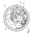
- the conveyor cylinders 48 of the thick matter pump 44 open into the front Material feed container 42. Your pistons are in the Hydraulic push-pull with the help of hydraulic cylinders 50 displaceable. Inside the material feed bin 42 is an S-shaped curved pipe switch 52, the inlet-side opening alternately in front of the Cylinder openings of the feed cylinder 48 pivoted is and its exit end 54 via a Pipe rotary connection to a delivery line leading to the outside 56 is connected.
- the control of the Thick matter pump 44 takes place via a hydraulic unit 58 and an electrical control unit 60.
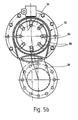
- the stone trap 36 shown in FIGS. 5a and b consists essentially of a cylindrical pot 82 with an inlet-side flange connection 84 for the transport pipe 30 and a laterally outgoing outlet outlet 38, and a screen 86, which is closed on the back by the cover 34 and is rigidly connected to it and at the end funnel-like towards the flange-side inlet opening 88 is open.
- This arrangement ensures that only such overburden that fits through the screen grid 86 to the thick matter pump 44 for removal is forwarded. With the overburden 32 arriving larger pieces collect in the sieve grid 86 and by removing the cover 34 together with the screen grid 86 from the stone trap 36 be removed.
- the starting shaft is opened 10 manufactured in the lowering process and the Press slide 12 in position within the starting shaft brought. Then the head 16 with With the help of the press slide 12 a little way into the tunneling section shifted in and the accruing Overburden removed from the starting shaft. step by step then the pipe pieces 62 in the starting shaft 10 lowered and with the press slide into the tunneling section 14 pressed.
- the thick matter pump 44 is mounted, the connected to the transport pipe 30 via the stone trap 36 becomes.
- the pressure side on the thick matter pump 44 outgoing conveyor line 56 is a two-armed Articulated tube 64 and the vertical line piece 66 led to the outside via the starting shaft 10.
- each pipe section 62 becomes a further line section 68 introduced into the starting shaft 10 and into the delivery line 56 engaged.
- the machine feed then takes place gradually over the press slide 12 one tube length each.
- sensors 70, 72, 74 the pressure in the cutting space 26 of the head 16, at the entrance to the stone trap 36 and inside the suction chamber 42 measured and monitored.
- About constipation within the thick matter pump 44 and the delivery line 56 to avoid oversized stones and roots and other contaminants that are in the ground could be intercepted with the help of the stone trap 36.
- the stone trap can be easily opened on its cover 34 for this purpose and be cleaned. This can be done automatically or done manually.
- an injection ring nozzle 76 is provided, via which a lubricant or water enters the delivery line can be injected.
- the invention relates to an arrangement for Driving along a tunnel or sewage pipe one from a starting shaft 10 to a target shaft leading heading section 14.
- the arrangement is in front especially for the production of micro tunnels or small tunnels determined where step by step pipe pieces 62 in the tunneling section against one arranged at the front Propulsion head 16 are pressed.
- To the Removal of the overburden 32 is one in the cutting area 26 of the feed head engaging screw conveyor provided at the outlet end a stone trap that can be closed in a pressure-tight manner 36 and the pressure side closable suction side 42 a thick matter pump 44 can be connected while the thick matter pump 44 on the pressure side with a successive extensible conveyor line 56 connected for the overburden is.
Landscapes
- Engineering & Computer Science (AREA)
- Mining & Mineral Resources (AREA)
- Life Sciences & Earth Sciences (AREA)
- Geology (AREA)
- Environmental & Geological Engineering (AREA)
- General Life Sciences & Earth Sciences (AREA)
- Geochemistry & Mineralogy (AREA)
- Physics & Mathematics (AREA)
- Fluid Mechanics (AREA)
- Excavating Of Shafts Or Tunnels (AREA)
Description
- Fig. 1
- eine nach dem Rohrpreßverfahren arbeitende Tunnelvortriebsmaschine in schaubildlicher Darstellung;
- Fig. 2
- eine Seitenansicht der Vortriebsmaschine nach Fig. 1;
- Fig. 3a bis d
- Schnitte entlang den Schnittlinien A-A, B-B, C-C und D-D der Fig. 2;
- Fig. 4
- eine vergrößerte Darstellung der Fig. 3d,
- Fig. 5a und b
- einen Längsschnitt durch die Steinfalle nach Fig. 2 und einen Schnitt entlang der Schnittlinie 5-5 der Fig. 5a.
Claims (14)
- Anordnung zum Vortrieb eines Tunnel- oder Abwasserrohrs entlang einer von einem Startschacht (10) zu einem Zielschacht führenden Vortriebsstrecke (14) mit einem einen zylindrischen Schildmantel (18) und eine stirnseitig um die Zentralachse des Schildmantels drehbare, motorisch antreibbare Schürtscheibe (22) aufweisenden Vortriebskopf (16), mit einem innerhalb des Startschachts an einem Widerlager abstützbaren Pressschlitten (12), der dazu bestimmt ist, eine Anzahl nacheinander über den Startschacht (10) in die Vortriebsstrecke (14) einführbare Rohrstücke (62), deren erstes Rohrstück axial gegen den Schildmantel (18) des Vortriebskopf (16) zur Anlage bringbar ist, axial in Richtung Vortriebsstrecke zu pressen, mit einem über Durchtrittsöffnungen in der Schürfscheibe (22) mit Abraum (32) beaufschlagbaren Schneidraum (26), mit einem vorzugsweise mit einer Förderschnecke oder einem Förderschneckenpaar bestückten Transportrohr (30) für den Abtransport des Abraums (32) aus dem Schneidraum (26), mit einer Abraumtransportstrecke, die Mittel zum austrittsseitigen Anschluss an das Transportrohr aufweist und mit einer Dickstoffpumpe (44) mit druckdicht verschließbareSaugseite (42) wobei die Dickstoffpumpe (44) druckseitig mit einer sukzessive verlängerbaren Förderleitung (56,68,66) für den Abraum (32) verbindbar ist, und wobei die Dickstoffpumpe (44) als hydraulisch betätigbare Kolbenpumpe mit einem oder zwei Förderzylindern (48) ausgebildet ist, dadurch gekennzeichnet, dass die Abraumtransportstrecke eine druckdicht verschließbare Steinfalle (36) umfasst, wobei die Steinfalle (36) und die druckdicht verschließbare Saugseite (42) der Dickstoffpumpe (44) hintereinander an das Transportrohr anschließbar sind und dass der oder die Förderzylinder (48) in- einen druckdicht verschließbaren Materialaufgabebehälter (42) mündet, bzw. münden, in welchen ein an die Förderleitung angeschlossener, abwechselnd an den oder die Förderzylinder (48) anschließbarer Rohrschieber (52) eingreift.
- Anordnung nach Anspruch 1, dadurch gekennzeichnet, dass die Dickstoffpumpe (44) in das gegen den Vortriebskopf (16) anliegende erste Rohrstück (62) montiert ist.
- Anordnung nach Anspruch 1 oder 2, dadurch gekennzeichnet, dass die Dickstoffpumpe (44) und ihre vorzugsweise hydraulischen Antriebsaggregate (58) an einer Schnittstelle auftrennbar und in zwei benachbarte Rohrstücke (62) montiert sind.
- Anordnung nach einem der Ansprüche 1 bis 3, gekennzeichnet durch mindestens zwei entlang der Abraumtransportstrecke angeordnete, in diese eingreifende Drucksensoren (72,74).
- Anordnung nach Anspruch 4, dadurch gekennzeichnet, dass je ein Drucksensor (72,74) unmittelbar vor und hinter der Steinfalle (36) angeordnet ist.
- Anordnung nach einem der Ansprüche 1 bis 5, gekennzeichnet durch einen in den Schneidraum (26) eingreifenden Drucksensor (70).
- Anordnung nach einem der Ansprüche 1 bis 6, gekennzeichnet durch mindestens einen in die Förderleitung (56) eingreifenden Drucksensor.
- Anordnung nach einem der Ansprüche 1 bis 7, dadurch gekennzeichnet, dass die Steinfalle (36) ein in einem druckdicht mit einem abnehmbaren Deckel (34) verschließbaren, eintrittsseitig an das Transportrohr (30) und austrittsseitig an die Saugseite (42) der Dickstoffpumpe (44) angeschlossenen Topf angeordnetes Siebgitter aufweist.
- Anordnung nach einem der Ansprüche 1 bis 7, dadurch gekennzeichnet, dass die Steinfalle (36) einen als Querschieber ausgebildeten, sich in Durchtrittsrichtung verjüngenden und/oder ein Siebgitter enthaltenden Durchlasskanal für den Abraum (32) aufweist.
- Anordnung nach einem der Ansprüche 1 bis 9, dadurch gekennzeichnet, dass die Dickstoffpumpe (44) und/oder ihre Antriebsaggregate (58) gegen die Hochachse des betreffenden Rohrstücks (62) unter Freilassung eines Freiraums (78) seitlich versetzt montiert sind und dass auf der Freiraumseite des Rohrstücks (62) ein Kontergewicht (80) angeordnet ist.
- Anordnung nach einem der Ansprüche 1 bis 10, dadurch gekennzeichnet, dass zwischen Transportrohr (30) des Vortriebskopfes (16) und Dickstoffpumpe (44) ein elastisch oder gelenkig verbiegbarer Kompensator (40) angeordnet ist.
- Anordnung nach einem der Ansprüche 1 bis 11, dadurch gekennzeichnet, dass zwischen Steinfalle (36) und Saugseite (42) der Dickstoffpumpe (44) ein elastisch verbiegbarer Kompensator (40) angeordnet ist.
- Anordnung nach einem der Ansprüche 1 bis 12, dadurch gekennzeichnet, dass in der Förderleitung (56) ein vorzugsweise als Gleitringdüse ausgebildeter Gleitmittelinjektor (76) angeordnet ist.
- Anordnung nach einem der Ansprüche 1 bis 13, dadurch gekennzeichnet, dass der Pressschlitten (12) ein an die Förderleitung (56) anschließbares Gelenkrohr (64) trägt.
Applications Claiming Priority (3)
| Application Number | Priority Date | Filing Date | Title |
|---|---|---|---|
| DE4415399A DE4415399C2 (de) | 1994-05-03 | 1994-05-03 | Anordnung zum Vortrieb eines Tunnel- oder Abwasserrohrs |
| DE4415399 | 1994-05-03 | ||
| PCT/EP1995/001137 WO1995030065A1 (de) | 1994-05-03 | 1995-03-25 | Anordnung zum vortrieb eines tunnel- oder abwasserrohrs |
Publications (3)
| Publication Number | Publication Date |
|---|---|
| EP0759117A1 EP0759117A1 (de) | 1997-02-26 |
| EP0759117B1 EP0759117B1 (de) | 2000-01-26 |
| EP0759117B2 true EP0759117B2 (de) | 2004-09-08 |
Family
ID=6517058
Family Applications (1)
| Application Number | Title | Priority Date | Filing Date |
|---|---|---|---|
| EP95915162A Expired - Lifetime EP0759117B2 (de) | 1994-05-03 | 1995-03-25 | Anordnung zum vortrieb eines tunnel- oder abwasserrohrs |
Country Status (4)
| Country | Link |
|---|---|
| US (1) | US5749678A (de) |
| EP (1) | EP0759117B2 (de) |
| DE (2) | DE4415399C2 (de) |
| WO (1) | WO1995030065A1 (de) |
Families Citing this family (19)
| Publication number | Priority date | Publication date | Assignee | Title |
|---|---|---|---|---|
| EP0788572B1 (de) * | 1995-08-17 | 2001-07-11 | Roland Beck | Verfahren zum unterfangen von bauwerken |
| FR2753254B1 (fr) * | 1996-09-09 | 1998-10-16 | Gaz De France | Procede de raccordement de conduits |
| DE102007002399B4 (de) * | 2007-01-10 | 2012-06-21 | Bhg Brechtel Gmbh | Verfahren und Vorrichtung zur Herstellung einer verrohrten Strangbohrung |
| DE202008004873U1 (de) | 2008-04-08 | 2008-07-10 | Voith Patent Gmbh | Auftragswalze |
| US9039330B1 (en) | 2010-06-01 | 2015-05-26 | LLAJ, Inc. | Pipe boring shield |
| IT1404615B1 (it) * | 2011-02-21 | 2013-11-29 | Elas Geotecnica Srl | Procedimento ed attrezzatura per la realizzazione di gallerie |
| CN102226400B (zh) * | 2011-05-31 | 2012-09-12 | 中铁隧道装备制造有限公司 | 预防土压平衡盾构机因摩阻力过大而卡滞的方法及系统 |
| JP6295454B2 (ja) * | 2013-11-20 | 2018-03-20 | 株式会社ココム | 透水管及び複合透水管並びに推進工法によるこれらの施工方法 |
| CN103899320B (zh) * | 2014-03-26 | 2016-02-03 | 中铁工程装备集团有限公司 | 直接铺管机 |
| EP3106608B1 (de) | 2015-06-19 | 2021-02-24 | Entreprenørfirmaet Østergaard A/S | Tunnelbaumaschine und verfahren zum graben eines tunnels |
| CN107503759A (zh) * | 2017-01-18 | 2017-12-22 | 王燏斌 | 一种用于顶管法的掘进装置及其施工法 |
| CN106759593A (zh) * | 2017-01-18 | 2017-05-31 | 王燏斌 | 一种用于地下建筑的切槽装置及其施工法 |
| CN107420056B (zh) * | 2017-09-29 | 2023-06-23 | 兰州理工大学 | 一种岩土质遗址加固钻机专用防尘装置 |
| JP7012600B2 (ja) * | 2018-05-11 | 2022-01-28 | 鹿島建設株式会社 | 圧送方法 |
| CN110005424B (zh) * | 2019-04-22 | 2024-11-22 | 中建三局基础设施建设投资有限公司 | 一种用于减弱盾构螺旋机喷涌的装置及其使用方法 |
| JP7398330B2 (ja) * | 2020-04-24 | 2023-12-14 | 株式会社アルファシビルエンジニアリング | 曲線状トンネル・地中梁又は先行支保を構築するための推進装置の発進設備 |
| CN113931633A (zh) * | 2021-09-28 | 2022-01-14 | 陕西能源凉水井矿业有限责任公司 | 一种ebz-160掘进机水系统 |
| CN117108824B (zh) * | 2023-10-24 | 2024-03-08 | 中隧方盾(天津)市政工程有限公司 | 一种应用于顶管施工的高精度距离控制装置 |
| JP2025124130A (ja) * | 2024-02-14 | 2025-08-26 | 誠 植村 | オープンシールド機 |
Citations (6)
| Publication number | Priority date | Publication date | Assignee | Title |
|---|---|---|---|---|
| US3915347A (en) † | 1972-10-13 | 1975-10-28 | Nat Res Dev | Double gate valve for passing material from a pressurized side of a bulkhead |
| US4116011A (en) † | 1976-06-04 | 1978-09-26 | Pablo Girault | Method of excavating tunnels |
| DE3537780A1 (de) † | 1985-07-26 | 1987-01-29 | Schweitzer Karl Friedrich | Vorrichtung zum herstellen von stollen oder tunnel durch schildvortrieb |
| DE2927324C2 (en) † | 1979-07-06 | 1988-08-25 | Friedrich Wilh. Schwing Gmbh, 4690 Herne, De | Cleaning device for concrete pump - has chamber containing cleaning ball, moved from external disengaged position into injection position |
| US4886396A (en) † | 1988-05-12 | 1989-12-12 | Kabushiki Kaisha Iseki Kaihatsu Koki | Existing pipeline renewing method and apparatus therefor |
| DE4202060A1 (de) † | 1992-01-25 | 1993-07-29 | Westfalia Becorit Ind Tech | Verfahren und einrichtung zum abdichten der abbaukammer einer schildvortriebseinrichtung an der dem haufwerksabzug dienenden foerdervorrichtung |
Family Cites Families (12)
| Publication number | Priority date | Publication date | Assignee | Title |
|---|---|---|---|---|
| US4576515A (en) * | 1982-09-20 | 1986-03-18 | Nippon Telegraph & Telephone Public Corp. | Pipe laying apparatus |
| DE3330635A1 (de) * | 1983-08-25 | 1985-03-21 | Wayss & Freytag Ag, 6000 Frankfurt | Vortriebsschild |
| DE3403890C1 (de) * | 1984-02-04 | 1985-03-14 | Hochtief Ag Vorm. Gebr. Helfmann, 4300 Essen | Foerdereinrichtung fuer eine Vortriebsmaschine fuer Tunnel und Strecken |
| JPS62107199A (ja) * | 1985-11-01 | 1987-05-18 | 株式会社小松製作所 | シ−ルド掘進機の土砂搬出装置 |
| DE3537593C1 (de) * | 1985-10-16 | 1986-09-11 | Wayss & Freytag Ag, 6000 Frankfurt | Vortriebsschild |
| CN1008827B (zh) * | 1987-05-01 | 1990-07-18 | 霍蒂夫股份公司霍夫曼兄弟公司 | 挡土罩 |
| US4818026A (en) * | 1987-12-29 | 1989-04-04 | Kabushiki Kaisha Komatsu Seisakusho | Shield type tunneling apparatus |
| US4915543A (en) * | 1988-05-12 | 1990-04-10 | Kabushiki Kaisha Iseki Kaihatsu Koki | Existing pipeline renewing method and apparatus therefor |
| JPH06100075B2 (ja) * | 1988-05-16 | 1994-12-12 | 株式会社橋本設備工業所 | 推進工法における掘削土砂の排出方法 |
| JP2519105B2 (ja) * | 1989-07-28 | 1996-07-31 | 株式会社イセキ開発工機 | シ―ルド型トンネル掘削機 |
| US5203614A (en) * | 1991-06-17 | 1993-04-20 | The Robbins Company | Tunneling machine having liquid balance low flow slurry system |
| DE4315196A1 (de) * | 1993-05-07 | 1994-11-10 | Lars Dipl Ing Babendererde | Tunnelvortriebsmaschine |
-
1994
- 1994-05-03 DE DE4415399A patent/DE4415399C2/de not_active Expired - Fee Related
-
1995
- 1995-03-25 EP EP95915162A patent/EP0759117B2/de not_active Expired - Lifetime
- 1995-03-25 DE DE59507702T patent/DE59507702D1/de not_active Expired - Fee Related
- 1995-03-25 US US08/732,395 patent/US5749678A/en not_active Expired - Fee Related
- 1995-03-25 WO PCT/EP1995/001137 patent/WO1995030065A1/de not_active Ceased
Patent Citations (6)
| Publication number | Priority date | Publication date | Assignee | Title |
|---|---|---|---|---|
| US3915347A (en) † | 1972-10-13 | 1975-10-28 | Nat Res Dev | Double gate valve for passing material from a pressurized side of a bulkhead |
| US4116011A (en) † | 1976-06-04 | 1978-09-26 | Pablo Girault | Method of excavating tunnels |
| DE2927324C2 (en) † | 1979-07-06 | 1988-08-25 | Friedrich Wilh. Schwing Gmbh, 4690 Herne, De | Cleaning device for concrete pump - has chamber containing cleaning ball, moved from external disengaged position into injection position |
| DE3537780A1 (de) † | 1985-07-26 | 1987-01-29 | Schweitzer Karl Friedrich | Vorrichtung zum herstellen von stollen oder tunnel durch schildvortrieb |
| US4886396A (en) † | 1988-05-12 | 1989-12-12 | Kabushiki Kaisha Iseki Kaihatsu Koki | Existing pipeline renewing method and apparatus therefor |
| DE4202060A1 (de) † | 1992-01-25 | 1993-07-29 | Westfalia Becorit Ind Tech | Verfahren und einrichtung zum abdichten der abbaukammer einer schildvortriebseinrichtung an der dem haufwerksabzug dienenden foerdervorrichtung |
Non-Patent Citations (3)
| Title |
|---|
| Prospekt 2-ZYLINDER-DICKSTOFFPUMPEN, Fa. SCHWING, Herne, Nov. 1982 † |
| Prospekt DICKSTOFFPUMPEN-TECHNIK, Fa. SCHWING, Herne, Nov. 1992 † |
| Prospekt GUMMIKOMPENSATOREN, Fa. Kempchen, Oberhausen, Jan. 1989 † |
Also Published As
| Publication number | Publication date |
|---|---|
| EP0759117B1 (de) | 2000-01-26 |
| WO1995030065A1 (de) | 1995-11-09 |
| DE4415399C2 (de) | 2003-10-30 |
| DE59507702D1 (de) | 2000-03-02 |
| US5749678A (en) | 1998-05-12 |
| DE4415399A1 (de) | 1995-11-09 |
| EP0759117A1 (de) | 1997-02-26 |
Similar Documents
| Publication | Publication Date | Title |
|---|---|---|
| EP0759117B2 (de) | Anordnung zum vortrieb eines tunnel- oder abwasserrohrs | |
| DE19600897C1 (de) | Selbstfahrende Aufbereitungsanlage zum Naßklassieren von Kies und Sand | |
| DE4017013C2 (de) | Vorrichtung zum Reinigen von Brunnenschächten | |
| DE2657677B2 (de) | Verfahren und Vorrichtung zur pneumatischen Förderung von Schüttgütern, zähflieflenden Massen, Schlämmen o.dgl. in einer rohrförmigen Förderrinne | |
| DE19932416A1 (de) | Vorrichtung zum Entwässern von Schlamm | |
| EP2334874B1 (de) | Vorrichtung und verfahren zum aktivieren oder reinigen von brunnen | |
| DE4240297C2 (de) | Schildvortriebsmaschine mit einer Dickstoffkolbenpumpenfördereinrichtung | |
| DE9421937U1 (de) | Anordnung zum Vortrieb eines Tunnel- oder Abwasserrohrs | |
| DE3729561C2 (de) | ||
| DE3908216A1 (de) | Vorrichtung zur kanalreinigung | |
| DE2355831A1 (de) | Vorrichtung zum foerdern von schuettguetern | |
| DE3627270A1 (de) | Vortriebsschild, insbesondere fuer den vortrieb mit erddruckgestuetzter ortsbrust, mit einem schneckenfoerderer fuer die bodenfoerderung | |
| DE2510283C3 (de) | Mit Hilfe eines Lastkraftwagens transportierbare Vorrichtung zum Abscheiden von Feststoffen aus schlammartigem Müll oder Abfall | |
| DE102015110017A1 (de) | Vorrichtung zur Förderung des Abbaubodens in einer Schildvortriebsmaschine (SVM) | |
| CH515731A (de) | Einrichtung zur Reinigung von schüttbarem Filterstoff in mit Wasser gefüllten Wasseraufbereitungslangsamfiltern | |
| DE19617972B4 (de) | Vorrichtung und Verfahren zum Pelletieren von Schlamm | |
| EP0240672A1 (de) | Schürf- und Fördereinrichtung einer unterirdisch arbeitenden Vortriebsvorrichtung für Rohrleitungen | |
| DE102004001200B4 (de) | Vorrichtung zur Sedimentation von Feststoffpartikel enthaltendem Abwasser | |
| DE3537780A1 (de) | Vorrichtung zum herstellen von stollen oder tunnel durch schildvortrieb | |
| DE2744270C2 (de) | Teleskoprohr zum Einfüllen von Beton hinter eine Abschalung eines Streckenausbaus im Berg- und Tunnelbau | |
| DE3419158C2 (de) | ||
| DE19715816C1 (de) | Vorrichtung zum Aufnehmen und Behandeln eines Schmutzsubstrats | |
| DE2338670C3 (de) | Kläranlageneinrichtung | |
| DE2608673C2 (de) | Verfahren und Vorrichtung zum Vorbereiten einer festes, körniges Material enthaltenden Wassertrübe für das hydraulische Fördern des Materials unter Druck | |
| DE1915031C3 (de) | Fördervorrichtung für den Rohrvorpre (!betrieb |
Legal Events
| Date | Code | Title | Description |
|---|---|---|---|
| PUAI | Public reference made under article 153(3) epc to a published international application that has entered the european phase |
Free format text: ORIGINAL CODE: 0009012 |
|
| 17P | Request for examination filed |
Effective date: 19960809 |
|
| AK | Designated contracting states |
Kind code of ref document: A1 Designated state(s): DE NL |
|
| RAP1 | Party data changed (applicant data changed or rights of an application transferred) |
Owner name: PUTZMEISTER AKTIENGESELLSCHAFT |
|
| 17Q | First examination report despatched |
Effective date: 19970821 |
|
| GRAG | Despatch of communication of intention to grant |
Free format text: ORIGINAL CODE: EPIDOS AGRA |
|
| GRAG | Despatch of communication of intention to grant |
Free format text: ORIGINAL CODE: EPIDOS AGRA |
|
| GRAG | Despatch of communication of intention to grant |
Free format text: ORIGINAL CODE: EPIDOS AGRA |
|
| GRAH | Despatch of communication of intention to grant a patent |
Free format text: ORIGINAL CODE: EPIDOS IGRA |
|
| GRAH | Despatch of communication of intention to grant a patent |
Free format text: ORIGINAL CODE: EPIDOS IGRA |
|
| GRAA | (expected) grant |
Free format text: ORIGINAL CODE: 0009210 |
|
| AK | Designated contracting states |
Kind code of ref document: B1 Designated state(s): DE NL |
|
| REF | Corresponds to: |
Ref document number: 59507702 Country of ref document: DE Date of ref document: 20000302 |
|
| PLBQ | Unpublished change to opponent data |
Free format text: ORIGINAL CODE: EPIDOS OPPO |
|
| PLBI | Opposition filed |
Free format text: ORIGINAL CODE: 0009260 |
|
| PLBF | Reply of patent proprietor to notice(s) of opposition |
Free format text: ORIGINAL CODE: EPIDOS OBSO |
|
| 26 | Opposition filed |
Opponent name: SCHWING GMBH Effective date: 20001016 |
|
| NLR1 | Nl: opposition has been filed with the epo |
Opponent name: SCHWING GMBH |
|
| PLBF | Reply of patent proprietor to notice(s) of opposition |
Free format text: ORIGINAL CODE: EPIDOS OBSO |
|
| PLBF | Reply of patent proprietor to notice(s) of opposition |
Free format text: ORIGINAL CODE: EPIDOS OBSO |
|
| PLBQ | Unpublished change to opponent data |
Free format text: ORIGINAL CODE: EPIDOS OPPO |
|
| PLAB | Opposition data, opponent's data or that of the opponent's representative modified |
Free format text: ORIGINAL CODE: 0009299OPPO |
|
| R26 | Opposition filed (corrected) |
Opponent name: SCHWING GMBH Effective date: 20001016 |
|
| NLR1 | Nl: opposition has been filed with the epo |
Opponent name: SCHWING GMBH |
|
| PUAH | Patent maintained in amended form |
Free format text: ORIGINAL CODE: 0009272 |
|
| STAA | Information on the status of an ep patent application or granted ep patent |
Free format text: STATUS: PATENT MAINTAINED AS AMENDED |
|
| 27A | Patent maintained in amended form |
Effective date: 20040908 |
|
| AK | Designated contracting states |
Kind code of ref document: B2 Designated state(s): DE NL |
|
| NLR2 | Nl: decision of opposition |
Effective date: 20040908 |
|
| NLR3 | Nl: receipt of modified translations in the netherlands language after an opposition procedure | ||
| EN | Fr: translation not filed | ||
| PGFP | Annual fee paid to national office [announced via postgrant information from national office to epo] |
Ref country code: NL Payment date: 20080325 Year of fee payment: 14 |
|
| PLAB | Opposition data, opponent's data or that of the opponent's representative modified |
Free format text: ORIGINAL CODE: 0009299OPPO |
|
| NLT1 | Nl: modifications of names registered in virtue of documents presented to the patent office pursuant to art. 16 a, paragraph 1 |
Owner name: PUTZMEISTER CONCRETE PUMPS GMBH |
|
| PGFP | Annual fee paid to national office [announced via postgrant information from national office to epo] |
Ref country code: DE Payment date: 20090319 Year of fee payment: 15 |
|
| NLV4 | Nl: lapsed or anulled due to non-payment of the annual fee |
Effective date: 20091001 |
|
| PG25 | Lapsed in a contracting state [announced via postgrant information from national office to epo] |
Ref country code: NL Free format text: LAPSE BECAUSE OF NON-PAYMENT OF DUE FEES Effective date: 20091001 |
|
| PG25 | Lapsed in a contracting state [announced via postgrant information from national office to epo] |
Ref country code: DE Free format text: LAPSE BECAUSE OF NON-PAYMENT OF DUE FEES Effective date: 20101001 |