EP0759151B2 - Procede de correction et systeme de navigation pour le reperage a l'estime d'un vehicule a moteur - Google Patents
Procede de correction et systeme de navigation pour le reperage a l'estime d'un vehicule a moteur Download PDFInfo
- Publication number
- EP0759151B2 EP0759151B2 EP95915800A EP95915800A EP0759151B2 EP 0759151 B2 EP0759151 B2 EP 0759151B2 EP 95915800 A EP95915800 A EP 95915800A EP 95915800 A EP95915800 A EP 95915800A EP 0759151 B2 EP0759151 B2 EP 0759151B2
- Authority
- EP
- European Patent Office
- Prior art keywords
- path
- vehicle
- parallel
- main path
- correction method
- Prior art date
- Legal status (The legal status is an assumption and is not a legal conclusion. Google has not performed a legal analysis and makes no representation as to the accuracy of the status listed.)
- Expired - Lifetime
Links
Images

Classifications
-
- G—PHYSICS
- G01—MEASURING; TESTING
- G01C—MEASURING DISTANCES, LEVELS OR BEARINGS; SURVEYING; NAVIGATION; GYROSCOPIC INSTRUMENTS; PHOTOGRAMMETRY OR VIDEOGRAMMETRY
- G01C21/00—Navigation; Navigational instruments not provided for in groups G01C1/00 - G01C19/00
- G01C21/26—Navigation; Navigational instruments not provided for in groups G01C1/00 - G01C19/00 specially adapted for navigation in a road network
- G01C21/28—Navigation; Navigational instruments not provided for in groups G01C1/00 - G01C19/00 specially adapted for navigation in a road network with correlation of data from several navigational instruments
- G01C21/30—Map- or contour-matching
Definitions
- the invention is based on a correction method for the coupling location according to the preamble of claim 1.
- a map-based navigation system is already known to perform the position determination by a coupling location such that the data supplied by the sensors of a motor vehicle data are compared with those of a digitized road map.
- the determined by the coupling location vehicle position is corrected, wherein the vehicle is placed on a nearby running road. If, however, several roads run at a similar angle compared to the direction of travel of the vehicle, then it may happen that the vehicle is placed on the wrong road. In the course of the further journey, however, the vehicle remains on this "wrong road", since a further check for correctness of this position correction is not carried out.
- an error range is determined for the estimated vehicle position, whose size is predetermined by the tolerances of the sensors for the distance and the direction of travel.
- the vehicle positions calculated for a given driving situation are calculated for all roads within the error range.
- the vehicle position is determined as the actual position whose road course is closest.
- the inventive correction method according to claim 1 has the advantage that a plurality of possible vehicle positions are calculated simultaneously (in parallel), all routes within a driving area are taken into account. Even if a main path for the most likely vehicle position has been found, it remains only until a parallel path, due to plausibility considerations, reaches the greater likelihood of vehicle position. This results in the advantage that the navigation is reliable and the vehicle is always located on the road on which it is actually located.
- the measures listed in the dependent claims advantageous refinements and improvements of the correction method according to claim 1 are possible. It is particularly advantageous that the error range is always dimensioned by the inclusion of the measurement tolerances of the sensors and / or the navigation device so that the vehicle is certainly within the error ranges. This ensures that the possible locations for the vehicle are detected for all roads in the driving area.
- this main path is also selected, for example, taking into account the lifetime of the path or the angle of inclination, then the probability is high that it corresponds to the actual travel path of the vehicle.
- a valuation hysteresis is provided so that a change of the main path takes place only if, by several measurements this has proven to be plausible.
- a further advantage is that when using the invention in a destination management system, the route search is performed so that the main path is used as a starting point for the route calculation. Also, with path ambiguities (two or more paths with nearly equal plausibility), the destination route may become the decision criterion for the main path selection because of the likelihood that the vehicle driver will follow the system recommended route. By means of a parallel path evaluator and comparator, the desired main path can then be corrected at any time from the calculated parallel paths. If the navigation system has an indicator for a road map, then the current main path can be on a Display should be marked accordingly.
- FIG. 1 shows a first block diagram
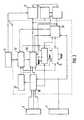
- FIG. 2 shows a second block diagram
- FIG. 3 shows a function diagram
- FIG. 4 shows a part of a digitized road map
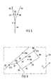
- FIG. 5 shows a further part of a digitized road map
- FIG. 6 shows a third part of a road map.
- Figure 1 shows a first block diagram of a map-based navigation system, in which a computing unit 1 is connected on the input side with vehicle sensors 3 for detecting the direction of travel and route. Furthermore, a satellite navigation receiver (for example GPS receiver) 4 is connected, with which a position determination of the vehicle is also possible. Furthermore, the arithmetic unit 1 is connected to an output unit 5, for example a display or an acoustic output. Furthermore, an input unit 6 and a destination guidance unit 7 are connected to the arithmetic unit 1. The route guidance unit 7 or the satellite receiver 4 are optionally provided.
- a computing unit 1 is connected on the input side with vehicle sensors 3 for detecting the direction of travel and route. Furthermore, a satellite navigation receiver (for example GPS receiver) 4 is connected, with which a position determination of the vehicle is also possible. Furthermore, the arithmetic unit 1 is connected to an output unit 5, for example a display or an acoustic output. Furthermore, an input unit 6 and a destination guidance unit 7 are connected to the arithmetic
- FIG. 2 shows in detail a second block diagram of the navigation system, in which the arithmetic unit 1 is shown with a plurality of function blocks.
- the arithmetic unit 1 contains a coupling location 19, in which the signals of the sensors 3 and / or the satellite receiver 4 are input.
- the coupling location 19 calculates a new position for the vehicle from the sensor signals and the previous position.
- the coupling location result and the sensor evaluation are given to an error estimator 21, which determines an error range 25 due to known tolerance errors (FIG. 4).
- the error range 25 is given to a selector 22, which is connected on the one hand to the card memory 2.
- the map memory 2 gives the roads to the selector 22, which fall into the driving area 24. This driving area 24 then corresponds to the main path and parallel path area of the road map (FIG. 4).
- the selector 22 is connected to a control computer 20 and forwards the main path and parallel path area to the control computer 20. Furthermore, the control computer 20 is connected to the coupling location 19 and receives from this the coupling location data for the vehicle.
- the control computer initially determines the main path independently of the parallel paths. Further possible vehicle positions next to the main path (parallel paths) are detected here and followed on the parallel path computers 11, 12. Each parallel path computer can in turn recognize several plausible vehicle positions and then start additional parallel paths on the parallel path computers.
- the parallel path computers are controlled via corresponding START control lines. Each parallel path computer is supplied with the map section of the driving area 24 via the selector 22.
- the parallel path computers 11, 12 are connected to a parallel path evaluator and comparator 23.
- the parallel path evaluator / comparator evaluates the parallel paths based on their status information (e.g., match of direction of travel and direction of the road). The parallel paths that are no longer plausible in the comparison of the parallel paths and the main path plausibility are deleted.
- the information of the absolute vehicle position and the estimated scattering range of a satellite navigation receiving and evaluating device 4 can also cause the deletion of parallel paths whose position is no longer in the scattering range of the satellite navigation position.
- the parallel path comparator 23 is connected to the coupling location 19, to which it can provide correction data for the vehicle position (path correction).
- this When using a route guidance unit 7, this also gives its data to the parallel path comparator 23, so that path ambiguities the path is selected as the main path that forms an element of the route to the destination.
- a correction of the coupling location position can also be done directly from the satellite receiving and evaluation device 4.
- the control computer 20 is connected to an output unit 5, on which, for example, in a graphic illustration, a road section is shown with the main path and a marking of the vehicle. However, it is also possible to provide directional arrows / driving recommendations or an acoustic output via the route guidance unit 7.
- the input unit 6 is connected on the one hand to the arithmetic unit 1, on the other hand to the destination guide unit 7, so that u.a. the destination input can be entered.
- FIG. 3 shows by way of example a function diagram for the position calculation and status determination of a parallel path by the parallel path computer 11, 12.
- the vehicle position X is to be calculated on a parallel path 31 that lies within the travel area 24.
- the parallel path computer 11, 12 extracts from the card memory 2 the card part corresponding to the travel area 24 (position a).
- position b the direction of travel and the travel distance of the motor vehicle, which was determined by the coupling location 19, entered.
- another parallel path computer 11, 12 can be started, if in this position calculation of the vehicle Again path ambiguities arise.
- a status is still determined in which, for example, a current match between the direction of travel and the road angle is determined.
- a probability factor for the vehicle position may be specified.
- the status information also contains information about the lifetime of the parallel path.
- Both the position and the status determination are passed via an output 11 to the parallel path comparator 23, which outputs a main path and current parallel paths from all available information on the basis of plausibility checks. For example, the inclination angle of a route can be compared with that of the vehicle and from this the main path can be determined. If a parallel path no longer falls into the driving area or if it no longer matches the coupling course, then it can be deleted via an input e.
- the function diagram can be designed as a program for the computer 1.
- Figure 4 shows a driving area 24, in which the passable roads 40 to 45 are shown. It is assumed that the vehicle is initially in position X on the road 40, which is currently designated as the main path. Bends now the vehicle from the right, then results due to the positive feedback and due to angular and longitudinal error of the vehicle sensors a position X1. Because of the errors, an error range 25 is formed around the position X1, as it has already been the position X. The error range 25 can be different for each calculated position X ... X4. The size of the error range is determined by the given tolerances. FIG. 4 therefore shows different error ranges 25 for the individual positions X... X4. The large, rectangular error field 25 of the position X moves, for example, with the new vehicle position X1, thereby changing its width.
- the new position X2 is therefore assumed on the road 43 which follows the calculated position X1 next.
- the control computer 20 now determines the possible positions X2, X3 and X4 with the corresponding new error ranges 25 on the parallel paths 42, 43 and 44 due to the turning angle of the vehicle compared to all roads that have formed a similar angle to the previous main path 40.
- the roads 42, 43, 44 are located in the error area of the path position X1.
- the road 41 forms a turning angle in the opposite direction and is therefore no longer suitable for determining the position.
- the described method in which parallel path positions (here X2, X3 and X4 on the streets 44, 43 and 42) emerge from the error area 25 of the main path, can likewise be applied by generating parallel paths from the error area 25 of a parallel path.
- the error area 25 includes the heading sense error and a one-dimensional location area (possible length error) or a two-dimensional location area (lateral and longitudinal error of the assumed position). Due to plausibility considerations, the position X2 with the new error field 25 is selected from the positions X1 to X4 as the new main path for which the greatest probability of the vehicle position exists.
- the positions X3, X4 on the parallel paths 42, 44 are further calculated and taken into account in the next selection.
- the turn-off point on the intersection 43, 40 can be used as a defined correlation point for the length measurement.
- the difference X1 - X2 can be used for length correction. Accordingly, the method for determining the parallel path positions x3 and x4 is to be performed.
- a position correction according to FIG. 5 can be carried out.
- the vehicle is on the main path 50 in the position X. It is now assumed that the main path 50 splits at a fork in two parallel paths 51, 52. Due to the coupling location, the vehicle would be at a certain time in position X5. Since position X5 is not a location on a road, possible locations X6 on parallel path 51 or X7 on parallel path 52 are acceptable. If the position is determined repeatedly, for example, the probability of the position X7 on the parallel path 52 is also due to the recommended route to the destination, which is now pursued as the main path.
- the parallel path 51 is furthermore relevant and is further calculated with the parallel path computer 11, 12. Due to the change in angle from position X5 to X7, a correction value for the direction determination results, which can be used as the basis for the further coupling location.
- FIG. 6 shows a third part of a road map of a navigation system in which a satellite navigation receiver 4 (eg GPS) is used for the coupling location correction.
- the satellite navigation receiver determines its position from the location of several navigation satellites. This position determination is also associated with a certain error. This error will be similar to the examples of Figures 4 or 5 compensated.
- road sections / parallel paths 61 to 68 are shown. If, for example, the GPS receiver 4 determines the position X8 as a possible location for the vehicle, then the position X9 on the parallel path 61 and X10 on the parallel path 63 are additionally calculated in the direction of travel D.
- positions X13 on 66, X14 on 67 and X12 on 68 can be calculated.
- a position of the motor vehicle on the parallel paths 64 or 65 is unlikely for reasons of plausibility and therefore decides.
- recalculation gives the greatest probability, for example for a position X11 on the parallel path 62, which now becomes the main path.
- the motor vehicle is now assumed at position X11 and this position is output, for example, on a display 5.
- the positions X9, X10, X12, X13, X14 on the original roads 61, 63, 68, 66, 67 are tracked to control the main path 62. However, they are not displayed on the display 5.
- the navigation system is coupled to a route guidance device 7, then after entering a destination via the input 6, a specific destination route is selected by the arithmetic unit 1.
- the target route is now set to be calculated with the new main path 62 as the starting position.
- the individual assemblies of the navigation system or the computing unit 1 such as the coupling location 19, the error estimator 21, the selector 22, the parallel path computers 11, 12 or the parallel path comparator 23 are constructed with known devices, such as amplifiers, comparators or logic devices. These are familiar to those skilled in the known navigation systems and therefore need not be explained in more detail. Instead of individual components, one or more microcomputers can also be provided, which are controlled by a corresponding control program.
Landscapes
- Engineering & Computer Science (AREA)
- Radar, Positioning & Navigation (AREA)
- Remote Sensing (AREA)
- Automation & Control Theory (AREA)
- Physics & Mathematics (AREA)
- General Physics & Mathematics (AREA)
- Navigation (AREA)
- Traffic Control Systems (AREA)
- Instructional Devices (AREA)
- Position Fixing By Use Of Radio Waves (AREA)
Claims (9)
- Procédé de correction d'un système de navigation s'appuyant sur des cartes et déterminant, par localisation à l'estime, une position fictive d'un véhicule automobile et donne cette position comme position réelle, de préférence sur une carte routière d'un moyen d'affichage, la position réelle étant définie en plaçant le véhicule sur une chaussée sensiblement parallèle à la direction de déplacement,• à partir des signaux fournis par les capteurs (3) du véhicule et/ou un appareil de navigation (4), on forme une zone de déplacement (24) pour la position réelle (X2 ; X7 ; X11) du véhicule, la position réelle, déterminée (X2 ; X7 ; X11) comprenant une zone d'erreur (25), prédéterminée pour les erreurs dans la direction longitudinale transversale et/ou d'orientation,• dans une mémoire à cartes (2) on prend toutes les chaussées qui se situent dans la zone de déplacement (24) formée, et constituant ainsi le chemin principal possible et les chemins parallèles possibles pour la trajectoire du véhicule,• par un contrôle de plausibilité, on place la position du chemin principal (X2 ; X7) sur la chaussée (43 ; 52) dans la zone d'erreur (25) du chemin principal (40 ; 50) actuel, qui se trouve le plus près de la trajectoire du véhicule définie par une localisation à l'estime,caractérisé en ce que- on poursuit les autres chemins avec leur position possible ((X3, X4 ; X9-X14) aussi longtemps qu'ils sont plausibles, comme chemins parallèles et- par d'autres contrôles de plausibilité on détermine comme nouveau chemin principal, le chemin principal actuel (43 ; 52 ; 62) ou l'un des chemins, parallèles si la trajectoire couplée coïncide le mieux avec le chemin respectif,• pour chaque chemin parallèle on prédéfinit une zone d'erreur respective donnée par les tolérances prédéterminées respectives des capteurs du véhicule,• la zone d'erreur (25) comprenant une zone à une ou deux dimensions pour les erreurs dans la direction longitudinale ou dans la direction longitudinale et dans la direction transversale, et/ou une zone de direction de déplacement, et• on utilise comme base pour la suite de l'orientation à l'estime, la différence entre une position mesurée et une position réelle du véhicule pour corriger les mesures dans la direction longitudinale et les mesures angulaires.
- Procédé de correction selon la revendication 1,
caractérisé en ce qu'
un chemin parallèle, qui découle d'un chemin parallèle ou d'un chemin principal, conserve tout d'abord l'évaluation et l'état de ce chemin principal ou parallèle. - Procédé de correction selon l'une quelconque des revendications précédentes,
caractérisé en ce que
comme nouveau chemin principal, on sélectionne le chemin parallèle dont la direction correspond sensiblement à la direction de déplacement couplée et/ou d'autres paramètres. - Procédé de correction selon l'une quelconque des revendications précédentes,
caractérisé en ce que
pour l'évaluation du chemin on tient compte de la concordance respective entre l'angle d'inclinaison du véhicule et l'angle de pente montant ou descendant du segment de chaussée et/ou la durée de vie du chemin. - Procédé de correction selon l'une quelconque des revendications précédentes,
caractérisé en ce que
pour l'évaluation du chemin principal (43 ; 52 ; 62) et du chemin parallèle on forme un comportement à hystérésis retardant tout changement d'un chemin parallèle à un autre. - Procédé de correction selon l'une quelconque des revendications précédentes,
caractérisé en ce qu'
on corrige l'erreur dans la direction longitudinale de la localisation à l'estime en ce qu'après un déplacement en courbe, on compare la position déterminée (X1) du véhicule à une position de chaussée (X2) située dans la plage d'erreur, et on utilise cette différence pour corriger l'erreur dans la direction longitudinale de la localisation à l'estime. - Procédé de correction selon l'une quelconque des revendications précédentes,
caractérisé en ce que
pour un positionnement nouveau du véhicule, on définit la position à l'aide d'un récepteur satellite à navigation, en ce qu'à côté du chemin principal (62) on forme des chemins parallèles (61, 63, 66, 67, 68) sur toutes les chaussées apparaissant comme plausibles, et qui sont sensiblement parallèles à la direction de déplacement (D) du véhicule (figure 6). - Procédé de correction selon la revendication 7,
caractérisé en ce qu'
on rejette les chemins parallèles qui sortent de la zone d'erreur de la détermination de position de navigation par satellite. - Procédé de correction selon l'une quelconque des revendications précédentes,
caractérisé en ce que
dans l'application d'un système de conduite vers un objectif (7), on fait passer le chemin principal actuel (43 ; 52 ; 62) en cas de caractère non univoque du chemin, de préférence le long du chemin de destination (figure 5).
Applications Claiming Priority (3)
| Application Number | Priority Date | Filing Date | Title |
|---|---|---|---|
| DE4415993 | 1994-05-06 | ||
| DE4415993A DE4415993A1 (de) | 1994-05-06 | 1994-05-06 | Korrekturverfahren und Navigationssystem für die Koppelortung eines Kraftfahrzeuges |
| PCT/DE1995/000536 WO1995030881A1 (fr) | 1994-05-06 | 1995-04-19 | Procede de correction et systeme de navigation pour le reperage a l'estime d'un vehicule a moteur |
Publications (3)
| Publication Number | Publication Date |
|---|---|
| EP0759151A1 EP0759151A1 (fr) | 1997-02-26 |
| EP0759151B1 EP0759151B1 (fr) | 2001-01-03 |
| EP0759151B2 true EP0759151B2 (fr) | 2007-02-14 |
Family
ID=6517450
Family Applications (1)
| Application Number | Title | Priority Date | Filing Date |
|---|---|---|---|
| EP95915800A Expired - Lifetime EP0759151B2 (fr) | 1994-05-06 | 1995-04-19 | Procede de correction et systeme de navigation pour le reperage a l'estime d'un vehicule a moteur |
Country Status (8)
| Country | Link |
|---|---|
| US (1) | US6002981A (fr) |
| EP (1) | EP0759151B2 (fr) |
| JP (1) | JPH10500208A (fr) |
| CZ (1) | CZ292499B6 (fr) |
| DE (2) | DE4415993A1 (fr) |
| HU (1) | HUT76227A (fr) |
| RU (1) | RU2151379C1 (fr) |
| WO (1) | WO1995030881A1 (fr) |
Cited By (2)
| Publication number | Priority date | Publication date | Assignee | Title |
|---|---|---|---|---|
| DE102008002602A1 (de) | 2008-06-24 | 2009-12-31 | Robert Bosch Gmbh | Positions- und Geschwindigkeitsermittlung eines Fahrzeugs |
| US8306748B2 (en) | 2009-10-05 | 2012-11-06 | Honeywell International Inc. | Location enhancement system and method based on topology constraints |
Families Citing this family (46)
| Publication number | Priority date | Publication date | Assignee | Title |
|---|---|---|---|---|
| DE19645209B4 (de) * | 1996-11-02 | 2005-07-28 | Robert Bosch Gmbh | Ortungsvorrichtung für ein Kraftfahrzeug mit einem Satellitenempfänger und Ortungsverfahren |
| DE19724407A1 (de) | 1997-06-10 | 1998-12-17 | Alsthom Cge Alcatel | Verfahren zur Ermittlung von Streckendaten |
| JP3582560B2 (ja) * | 1997-07-08 | 2004-10-27 | アイシン・エィ・ダブリュ株式会社 | 車両用ナビゲーション装置及び記録媒体 |
| CN100342405C (zh) | 1998-01-23 | 2007-10-10 | 丰田自动车株式会社 | 计费处理装置、计费处理系统、计费处理用卡 |
| DE19803662C2 (de) * | 1998-01-30 | 1999-12-02 | Siemens Ag | Navigationsgerät und Verfahren zur Positionsbestimmung mittels Koppelnavigation |
| US6678556B1 (en) * | 1998-07-13 | 2004-01-13 | Genetronics, Inc. | Electrical field therapy with reduced histopathological change in muscle |
| CN1316436C (zh) * | 1998-10-09 | 2007-05-16 | 丰田自动车株式会社 | 计费装置 |
| JP3852647B2 (ja) * | 1998-11-04 | 2006-12-06 | 株式会社小松製作所 | 車両の誘導装置 |
| DE19856184A1 (de) * | 1998-12-05 | 2000-06-08 | Alcatel Sa | Verfahren zur fahrzeuginternen Feststellung, ob sich das Fahrzeug auf einer von mehreren vorgegebenen Straßen befindet |
| DE19915212A1 (de) | 1999-04-03 | 2000-10-05 | Bosch Gmbh Robert | Verfahren und Vorrichtung zur Bestimmung der Position eines Fahrzeugs |
| US20040215387A1 (en) * | 2002-02-14 | 2004-10-28 | Matsushita Electric Industrial Co., Ltd. | Method for transmitting location information on a digital map, apparatus for implementing the method, and traffic information provision/reception system |
| JP3481168B2 (ja) * | 1999-08-27 | 2003-12-22 | 松下電器産業株式会社 | デジタル地図の位置情報伝達方法 |
| US6374184B1 (en) | 1999-09-10 | 2002-04-16 | Ge-Harris Railway Electronics, Llc | Methods and apparatus for determining that a train has changed paths |
| DE19945123C2 (de) * | 1999-09-21 | 2001-12-13 | Mannesmann Vdo Ag | Verfahren zum Navigieren eines Fahrzeugs |
| US6282496B1 (en) * | 1999-10-29 | 2001-08-28 | Visteon Technologies, Llc | Method and apparatus for inertial guidance for an automobile navigation system |
| US6356838B1 (en) * | 2000-07-25 | 2002-03-12 | Sunil Paul | System and method for determining an efficient transportation route |
| DE60123449T2 (de) * | 2000-09-29 | 2007-08-23 | Toyota Jidosha Kabushiki Kaisha, Toyota | Positionserkennungseinrichtung und positionserkennungsverfahren und verwaltungseinrichtung und verwaltungsverfahren |
| JP5041638B2 (ja) | 2000-12-08 | 2012-10-03 | パナソニック株式会社 | デジタル地図の位置情報伝達方法とそれに使用する装置 |
| RU2184349C1 (ru) * | 2000-12-18 | 2002-06-27 | Государственное унитарное предприятие "Всероссийский научно-исследовательский институт "Сигнал" | Аппаратура счисления координат с автоматической коррекцией показаний |
| JP4663136B2 (ja) | 2001-01-29 | 2011-03-30 | パナソニック株式会社 | デジタル地図の位置情報伝達方法と装置 |
| JP4749594B2 (ja) | 2001-04-27 | 2011-08-17 | パナソニック株式会社 | デジタル地図の位置情報伝達方法 |
| JP4230132B2 (ja) * | 2001-05-01 | 2009-02-25 | パナソニック株式会社 | デジタル地図の形状ベクトルの符号化方法と位置情報伝達方法とそれを実施する装置 |
| US6560531B1 (en) * | 2001-05-22 | 2003-05-06 | Navigation Technologies Corporation | Multi-resolution trend metric for shape comparison and applications thereof |
| US6560532B2 (en) | 2001-05-25 | 2003-05-06 | Regents Of The University Of California, The | Method and system for electronically determining dynamic traffic information |
| RU2193755C1 (ru) * | 2001-06-04 | 2002-11-27 | Государственное унитарное предприятие "Всероссийский научно-исследовательский институт "Сигнал" | Аппаратура счисления координат широкого применения |
| EP1265054A1 (fr) * | 2001-06-08 | 2002-12-11 | Itinerary Systems, ISAB | Système de navigation véhiculaire |
| US7038619B2 (en) | 2001-12-31 | 2006-05-02 | Rdp Associates, Incorporated | Satellite positioning system enabled media measurement system and method |
| DE10205453A1 (de) * | 2002-02-08 | 2003-08-28 | Albert Renftle | Positionsbestimmungsverfahren für ein Verkehrsgebühren-Erhebungssystem |
| US7565155B2 (en) | 2002-04-10 | 2009-07-21 | Networks In Motion | Method and system for dynamic estimation and predictive route generation |
| MX2007001250A (es) * | 2004-07-30 | 2008-01-18 | Nielsen Media Res Inc | Metodos y aparato para mejorar la exactiud y alcance de los sistemas de medicion de la exposicion a los medios electronicos. |
| KR100891662B1 (ko) * | 2005-10-05 | 2009-04-02 | 엘지전자 주식회사 | 비디오 신호 디코딩 및 인코딩 방법 |
| CN101287963B (zh) * | 2005-11-30 | 2012-07-04 | 爱信艾达株式会社 | 路径引导系统及路径引导方法 |
| US20090177382A1 (en) * | 2008-01-03 | 2009-07-09 | Commscope, Inc. Of North Carolina | Calibration of a Navigation System |
| US8725407B2 (en) | 2009-11-09 | 2014-05-13 | United Parcel Service Of America, Inc. | Enhanced location information for points of interest |
| US8335643B2 (en) * | 2010-08-10 | 2012-12-18 | Ford Global Technologies, Llc | Point of interest search, identification, and navigation |
| DE102012213754A1 (de) | 2012-08-03 | 2014-02-06 | Robert Bosch Gmbh | Verfahren und Informationssystem zum Abgleichen eines Sensorsignals eines Sensors in einem Fahrzeug |
| US9671233B2 (en) | 2012-11-08 | 2017-06-06 | Uber Technologies, Inc. | Dynamically providing position information of a transit object to a computing device |
| US20140278838A1 (en) | 2013-03-14 | 2014-09-18 | Uber Technologies, Inc. | Determining an amount for a toll based on location data points provided by a computing device |
| DE102013217060B4 (de) | 2013-08-27 | 2023-08-03 | Bayerische Motoren Werke Aktiengesellschaft | Spurgenaue Positionierung eines Fahrzeugs |
| DE102014204364A1 (de) | 2014-03-10 | 2015-09-10 | Robert Bosch Gmbh | Verfahren zum Ermitteln einer Position eines Objekts |
| US10424036B2 (en) | 2014-06-02 | 2019-09-24 | Uber Technologies, Inc. | Maintaining data for use with a transport service during connectivity loss between systems |
| US10730626B2 (en) | 2016-04-29 | 2020-08-04 | United Parcel Service Of America, Inc. | Methods of photo matching and photo confirmation for parcel pickup and delivery |
| US9969495B2 (en) | 2016-04-29 | 2018-05-15 | United Parcel Service Of America, Inc. | Unmanned aerial vehicle pick-up and delivery systems |
| US10775792B2 (en) | 2017-06-13 | 2020-09-15 | United Parcel Service Of America, Inc. | Autonomously delivering items to corresponding delivery locations proximate a delivery route |
| US10796423B2 (en) | 2017-09-29 | 2020-10-06 | United Parcel Service Of America, Inc. | Predictive parcel damage identification, analysis, and mitigation |
| US10934093B2 (en) | 2017-11-14 | 2021-03-02 | United Parcel Service Of America, Inc | Automated package transport vehicle |
Family Cites Families (10)
| Publication number | Priority date | Publication date | Assignee | Title |
|---|---|---|---|---|
| US4796191A (en) * | 1984-06-07 | 1989-01-03 | Etak, Inc. | Vehicle navigational system and method |
| US4807127A (en) * | 1986-12-10 | 1989-02-21 | Sumitomo Electric Industries, Ltd. | Vehicle location detecting system |
| WO1988008961A1 (fr) * | 1987-05-11 | 1988-11-17 | Sumitomo Electric Industries, Ltd. | Systeme detecteur de position |
| US4964052A (en) * | 1987-10-30 | 1990-10-16 | Nec Home Electronics Ltd. | Navigation device for use in a vehicle |
| JP2586069B2 (ja) * | 1987-11-19 | 1997-02-26 | ソニー株式会社 | 車載用ナビゲータ装置 |
| NL9001810A (nl) * | 1990-08-13 | 1992-03-02 | Philips Nv | Werkwijze voor de positiebepaling van een voertuig, inrichting voor de positiebepaling van een voertuig, alsmede voertuig voorzien van de inrichting. |
| US5359529A (en) * | 1992-05-15 | 1994-10-25 | Zexel Corporation | Route guidance on/off-route state filter |
| US5374933A (en) * | 1993-01-05 | 1994-12-20 | Zexel Corporation | Position correction method for vehicle navigation system |
| JPH06347278A (ja) * | 1993-06-10 | 1994-12-20 | Alpine Electron Inc | 車両の存在リンク検出方法 |
| JP3442138B2 (ja) * | 1994-04-28 | 2003-09-02 | パイオニア株式会社 | ナビゲーション装置及び方法 |
-
1994
- 1994-05-06 DE DE4415993A patent/DE4415993A1/de not_active Ceased
-
1995
- 1995-04-19 CZ CZ19963243A patent/CZ292499B6/cs not_active IP Right Cessation
- 1995-04-19 RU RU96119778/28A patent/RU2151379C1/ru not_active IP Right Cessation
- 1995-04-19 WO PCT/DE1995/000536 patent/WO1995030881A1/fr not_active Ceased
- 1995-04-19 US US08/737,214 patent/US6002981A/en not_active Expired - Lifetime
- 1995-04-19 JP JP7528584A patent/JPH10500208A/ja active Pending
- 1995-04-19 HU HU9603066A patent/HUT76227A/hu unknown
- 1995-04-19 DE DE59508940T patent/DE59508940D1/de not_active Expired - Lifetime
- 1995-04-19 EP EP95915800A patent/EP0759151B2/fr not_active Expired - Lifetime
Cited By (3)
| Publication number | Priority date | Publication date | Assignee | Title |
|---|---|---|---|---|
| DE102008002602A1 (de) | 2008-06-24 | 2009-12-31 | Robert Bosch Gmbh | Positions- und Geschwindigkeitsermittlung eines Fahrzeugs |
| DE102008002602B4 (de) | 2008-06-24 | 2022-03-31 | Robert Bosch Gmbh | Positions- und Geschwindigkeitsermittlung eines Fahrzeugs |
| US8306748B2 (en) | 2009-10-05 | 2012-11-06 | Honeywell International Inc. | Location enhancement system and method based on topology constraints |
Also Published As
| Publication number | Publication date |
|---|---|
| EP0759151B1 (fr) | 2001-01-03 |
| US6002981A (en) | 1999-12-14 |
| DE59508940D1 (de) | 2001-02-08 |
| WO1995030881A1 (fr) | 1995-11-16 |
| CZ324396A3 (en) | 1997-02-12 |
| RU2151379C1 (ru) | 2000-06-20 |
| JPH10500208A (ja) | 1998-01-06 |
| DE4415993A1 (de) | 1995-11-09 |
| HUT76227A (en) | 1997-07-28 |
| EP0759151A1 (fr) | 1997-02-26 |
| HU9603066D0 (en) | 1997-01-28 |
| CZ292499B6 (cs) | 2003-10-15 |
Similar Documents
| Publication | Publication Date | Title |
|---|---|---|
| EP0759151B1 (fr) | Procede de correction et systeme de navigation pour le reperage a l'estime d'un vehicule a moteur | |
| DE69325656T2 (de) | Verfahren/nichtverfahren-zustandsfilter für routenführungssystem | |
| DE10030455B4 (de) | Vorrichtung zum Erzeugen von Straßeninformationen aus einer gespeicherten digitalen Kartendatenbank | |
| DE69509587T2 (de) | Verfahren und Vorrichtung zum Feststellen eines Fahrzeugazimuths | |
| DE4033527C2 (de) | Fahrzeugpositionsdetektoreinrichtung | |
| DE68919956T2 (de) | Navigationssystem und -methode unter Benutzung von Landkartendaten. | |
| EP0979387B1 (fr) | Appareil de navigation et procede de determination de position par navigation couplee | |
| DE69730463T2 (de) | Verfahren und Vorrichtung zum Eingeben von Routen in einem Navigationssystem | |
| DE69303530T2 (de) | Vorrichtung zur Bestimmung der Position eines Fahrzeuges | |
| DE10052194B4 (de) | Navigationssystem mit einer Fahrtrouten-Ersetzungsfunktion | |
| DE60027879T2 (de) | ROUTENFüHRUNGSVORRICHTUNG | |
| DE20022617U1 (de) | Vorrichtung zur Erfassung der Position von einem Fahrzeug in einem vorgegebenen Bereich, insbesondere einer Lagereinrichtung, und zugehörige Bezugsmarkierung | |
| EP0935760B1 (fr) | Systeme de localisation pour vehicule dote d'un recepteur de satellite | |
| EP1279003B1 (fr) | Procede de determination de position et appareil de navigation | |
| DE3719702A1 (de) | Verfahren und einrichtung zur navigation | |
| DE102016011366A1 (de) | Verfahren zur Positionsbestimmung eines Fahrzeugs | |
| DE112016002192T5 (de) | Positionserfassungsvorrichtung für mobilen Körper und Positionserfassungsverfahren für mobilen Körper | |
| DE69526410T2 (de) | Verfahren zur bestimmung einer richtungsänderung während der fahrzeugnavigation, vorrichtung zur durchführung dieses verfahrens und fahrzeug mit einer solchen vorrichtung | |
| DE19937689A1 (de) | Bestimmung eines Ausgangsnullpegels eines Winkelgeschwindigkeitssensors | |
| WO2011098107A1 (fr) | Procédé de détermination d'un tracé de voie d'un trajet | |
| DE3538908A1 (de) | Bordautonomes ortungssystem fuer positionsermittlung und kollisionsschutz von roboter- und flurfoerderfahrzeugen | |
| DE68907403T2 (de) | Fahrzeugnavigationssystem. | |
| DE4230299B4 (de) | Verfahren zur Ortung eines Landfahrzeuges | |
| DE19818473C2 (de) | Verfahren zur Bestimmung der Position eines Fahrzeugs | |
| EP0196498A2 (fr) | Methode de localisation et de navigation pour véhicules terrestres |
Legal Events
| Date | Code | Title | Description |
|---|---|---|---|
| PUAI | Public reference made under article 153(3) epc to a published international application that has entered the european phase |
Free format text: ORIGINAL CODE: 0009012 |
|
| 17P | Request for examination filed |
Effective date: 19961206 |
|
| AK | Designated contracting states |
Kind code of ref document: A1 Designated state(s): CH DE FR GB IT LI SE |
|
| RIN1 | Information on inventor provided before grant (corrected) |
Inventor name: KREFT, PETER |
|
| 17Q | First examination report despatched |
Effective date: 19980803 |
|
| GRAG | Despatch of communication of intention to grant |
Free format text: ORIGINAL CODE: EPIDOS AGRA |
|
| GRAG | Despatch of communication of intention to grant |
Free format text: ORIGINAL CODE: EPIDOS AGRA |
|
| GRAH | Despatch of communication of intention to grant a patent |
Free format text: ORIGINAL CODE: EPIDOS IGRA |
|
| GRAH | Despatch of communication of intention to grant a patent |
Free format text: ORIGINAL CODE: EPIDOS IGRA |
|
| GRAA | (expected) grant |
Free format text: ORIGINAL CODE: 0009210 |
|
| AK | Designated contracting states |
Kind code of ref document: B1 Designated state(s): CH DE FR GB IT LI SE |
|
| REG | Reference to a national code |
Ref country code: CH Ref legal event code: EP |
|
| REF | Corresponds to: |
Ref document number: 59508940 Country of ref document: DE Date of ref document: 20010208 |
|
| REG | Reference to a national code |
Ref country code: CH Ref legal event code: NV Representative=s name: SCINTILLA AG, DIREKTION |
|
| ITF | It: translation for a ep patent filed | ||
| ET | Fr: translation filed | ||
| GBT | Gb: translation of ep patent filed (gb section 77(6)(a)/1977) |
Effective date: 20010308 |
|
| PLBI | Opposition filed |
Free format text: ORIGINAL CODE: 0009260 |
|
| 26 | Opposition filed |
Opponent name: DAIMLERCHRYSLER AG Effective date: 20010905 |
|
| PLBF | Reply of patent proprietor to notice(s) of opposition |
Free format text: ORIGINAL CODE: EPIDOS OBSO |
|
| REG | Reference to a national code |
Ref country code: GB Ref legal event code: IF02 |
|
| PLBF | Reply of patent proprietor to notice(s) of opposition |
Free format text: ORIGINAL CODE: EPIDOS OBSO |
|
| PLBF | Reply of patent proprietor to notice(s) of opposition |
Free format text: ORIGINAL CODE: EPIDOS OBSO |
|
| PUAH | Patent maintained in amended form |
Free format text: ORIGINAL CODE: 0009272 |
|
| STAA | Information on the status of an ep patent application or granted ep patent |
Free format text: STATUS: PATENT MAINTAINED AS AMENDED |
|
| 27A | Patent maintained in amended form |
Effective date: 20070214 |
|
| AK | Designated contracting states |
Kind code of ref document: B2 Designated state(s): CH DE FR GB IT LI SE |
|
| REG | Reference to a national code |
Ref country code: CH Ref legal event code: AEN Free format text: AUFRECHTERHALTUNG DES PATENTES IN GEAENDERTER FORM |
|
| REG | Reference to a national code |
Ref country code: SE Ref legal event code: RPEO |
|
| GBTA | Gb: translation of amended ep patent filed (gb section 77(6)(b)/1977) | ||
| ET3 | Fr: translation filed ** decision concerning opposition | ||
| PGFP | Annual fee paid to national office [announced via postgrant information from national office to epo] |
Ref country code: SE Payment date: 20091222 Year of fee payment: 16 |
|
| PGFP | Annual fee paid to national office [announced via postgrant information from national office to epo] |
Ref country code: GB Payment date: 20100324 Year of fee payment: 16 |
|
| PGFP | Annual fee paid to national office [announced via postgrant information from national office to epo] |
Ref country code: CH Payment date: 20100426 Year of fee payment: 16 |
|
| REG | Reference to a national code |
Ref country code: SE Ref legal event code: EUG |
|
| REG | Reference to a national code |
Ref country code: CH Ref legal event code: PL |
|
| GBPC | Gb: european patent ceased through non-payment of renewal fee |
Effective date: 20110419 |
|
| PG25 | Lapsed in a contracting state [announced via postgrant information from national office to epo] |
Ref country code: LI Free format text: LAPSE BECAUSE OF NON-PAYMENT OF DUE FEES Effective date: 20110430 Ref country code: CH Free format text: LAPSE BECAUSE OF NON-PAYMENT OF DUE FEES Effective date: 20110430 |
|
| PG25 | Lapsed in a contracting state [announced via postgrant information from national office to epo] |
Ref country code: GB Free format text: LAPSE BECAUSE OF NON-PAYMENT OF DUE FEES Effective date: 20110419 |
|
| PG25 | Lapsed in a contracting state [announced via postgrant information from national office to epo] |
Ref country code: SE Free format text: LAPSE BECAUSE OF NON-PAYMENT OF DUE FEES Effective date: 20110420 |
|
| PGFP | Annual fee paid to national office [announced via postgrant information from national office to epo] |
Ref country code: FR Payment date: 20140416 Year of fee payment: 20 Ref country code: DE Payment date: 20140626 Year of fee payment: 20 Ref country code: IT Payment date: 20140424 Year of fee payment: 20 |
|
| REG | Reference to a national code |
Ref country code: DE Ref legal event code: R071 Ref document number: 59508940 Country of ref document: DE |