EP0759374B1 - Vorrichtung zum Verstellen eines Sitzes in einem Kraftfahrzeug - Google Patents
Vorrichtung zum Verstellen eines Sitzes in einem Kraftfahrzeug Download PDFInfo
- Publication number
- EP0759374B1 EP0759374B1 EP96110935A EP96110935A EP0759374B1 EP 0759374 B1 EP0759374 B1 EP 0759374B1 EP 96110935 A EP96110935 A EP 96110935A EP 96110935 A EP96110935 A EP 96110935A EP 0759374 B1 EP0759374 B1 EP 0759374B1
- Authority
- EP
- European Patent Office
- Prior art keywords
- component
- bracket
- housing
- threaded
- shoulder
- Prior art date
- Legal status (The legal status is an assumption and is not a legal conclusion. Google has not performed a legal analysis and makes no representation as to the accuracy of the status listed.)
- Expired - Lifetime
Links
- 230000013011 mating Effects 0.000 claims 2
- 230000001681 protective effect Effects 0.000 description 3
- 206010039203 Road traffic accident Diseases 0.000 description 2
- 239000000463 material Substances 0.000 description 2
- 230000001419 dependent effect Effects 0.000 description 1
- 238000006073 displacement reaction Methods 0.000 description 1
- 230000000694 effects Effects 0.000 description 1
- 238000004519 manufacturing process Methods 0.000 description 1
- 239000002184 metal Substances 0.000 description 1
Images
Classifications
-
- B—PERFORMING OPERATIONS; TRANSPORTING
- B60—VEHICLES IN GENERAL
- B60N—SEATS SPECIALLY ADAPTED FOR VEHICLES; VEHICLE PASSENGER ACCOMMODATION NOT OTHERWISE PROVIDED FOR
- B60N2/00—Seats specially adapted for vehicles; Arrangement or mounting of seats in vehicles
- B60N2/02—Seats specially adapted for vehicles; Arrangement or mounting of seats in vehicles the seat or part thereof being movable, e.g. adjustable
- B60N2/04—Seats specially adapted for vehicles; Arrangement or mounting of seats in vehicles the seat or part thereof being movable, e.g. adjustable the whole seat being movable
- B60N2/06—Seats specially adapted for vehicles; Arrangement or mounting of seats in vehicles the seat or part thereof being movable, e.g. adjustable the whole seat being movable slidable
- B60N2/067—Seats specially adapted for vehicles; Arrangement or mounting of seats in vehicles the seat or part thereof being movable, e.g. adjustable the whole seat being movable slidable by linear actuators, e.g. linear screw mechanisms
-
- B—PERFORMING OPERATIONS; TRANSPORTING
- B60—VEHICLES IN GENERAL
- B60N—SEATS SPECIALLY ADAPTED FOR VEHICLES; VEHICLE PASSENGER ACCOMMODATION NOT OTHERWISE PROVIDED FOR
- B60N2/00—Seats specially adapted for vehicles; Arrangement or mounting of seats in vehicles
- B60N2/02—Seats specially adapted for vehicles; Arrangement or mounting of seats in vehicles the seat or part thereof being movable, e.g. adjustable
- B60N2/0224—Non-manual adjustments, e.g. with electrical operation
-
- B—PERFORMING OPERATIONS; TRANSPORTING
- B60—VEHICLES IN GENERAL
- B60N—SEATS SPECIALLY ADAPTED FOR VEHICLES; VEHICLE PASSENGER ACCOMMODATION NOT OTHERWISE PROVIDED FOR
- B60N2/00—Seats specially adapted for vehicles; Arrangement or mounting of seats in vehicles
- B60N2/02—Seats specially adapted for vehicles; Arrangement or mounting of seats in vehicles the seat or part thereof being movable, e.g. adjustable
- B60N2/0224—Non-manual adjustments, e.g. with electrical operation
- B60N2/02246—Electric motors therefor
- B60N2/02253—Electric motors therefor characterised by the transmission between the electric motor and the seat or seat parts
-
- B—PERFORMING OPERATIONS; TRANSPORTING
- B60—VEHICLES IN GENERAL
- B60N—SEATS SPECIALLY ADAPTED FOR VEHICLES; VEHICLE PASSENGER ACCOMMODATION NOT OTHERWISE PROVIDED FOR
- B60N2/00—Seats specially adapted for vehicles; Arrangement or mounting of seats in vehicles
- B60N2/90—Details or parts not otherwise provided for
- B60N2/919—Positioning and locking mechanisms
- B60N2/929—Positioning and locking mechanisms linear
Definitions
- the invention relates to a device for adjusting a Seat in a motor vehicle according to the genus of Main claim.
- the constant considerations for cost-cutting Measures for adjusting devices of the one in question kind cause the metal gear housing to be a known one Manufacture adjustment device made of plastic.
- the gearbox in the power flow from the fixed part of the Seat is included to the movable component, it must be next the forces occurring during normal operation are also considerable can transmit larger forces that occur when the motor vehicle - for example at a Traffic accident - is subjected to an extreme delay. In such a case, however, the vehicle seat should be firmly attached Bodywork remain connected so that for those on the seat provided person provided Protective measures - seat belt, airbag, etc. - yours Task in the intended manner.
- Plastic gearboxes are not always able to absorb the aforementioned forces undamaged and to derive.
- the counter shoulder is through the end face facing the support part one on the Threaded spindle formed threaded bush.
- a particularly simple and reliable embodiment of the Invention results when the support member as a U-shaped Bracket is formed, the two U-legs connecting web has the support shoulder.
- the U-bracket is useful in the area of the free ends of its U-legs with one belonging to the drive unit, truss-like housing part connected.
- the guide of the movable component is the U-bracket with the Housing part articulated.
- a simple, stable joint between the U-bracket and the Housing part if this has a hinge pin, the both the gearbox and the two U-legs of the bracket serving as a support part.
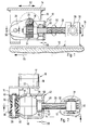
- FIG. 1 shows a side view of a Adjustment device for the seat in a motor vehicle, partly along a line I-I shown in Figure 2 cut and Figure 2 is a plan view of the Adjustment device according to Figure 1, partially along the lines II-II shown in figure shown in section is.
- a device 10 for adjustment shown in FIG of a seat in a motor vehicle has a body-fixed arranged component 12, in contrast one with Component not shown in the vehicle seat 14 can be moved.
- this is on the movably arranged, slide-like component 14 a drive unit 16 is arranged that an electrical Drive motor 17 and a subordinate to this Worm gear 18 contains.
- the worm gear 18 has a worm shaft 20 which is connected to an output shaft 22 of the drive unit 16 is operatively connected.
- the Drive unit 16 is on its housing attached, truss-like housing part 19 with the sled-shaped component 14 firmly connected.
- the Worm shaft 20 of worm gear 18 meshes with one Worm wheel 24 that rotates on a threaded spindle 26 is arranged.
- the threaded spindle 26 is in the range of Worm wheel 24 in a plastic Gear housing 28 rotatably mounted. That is further Threaded spindle 26 rotatably guided in a threaded nut 30, in a bearing block 32 in the direction of the double arrow 34 is pendulum suspended.
- the bearing block 32 is fixed to the frame-fixed component 12 of the adjusting device 10 connected.
- the gear housing 28 is about that truss-like housing part 19 with the drive unit 16 connected.
- the connection is an articulated connection executed. For this purpose, it has two shells 35 and 36 assembled gear housing 28 has a transverse bore, which is penetrated by a hinge pin 38.
- the hinge pin 38 continues to penetrate bores, which in support tabs 40th of the truss-like housing part 19 are arranged.
- the The hinge axis of the hinge pin 38 lies at least approximately parallel to the pendulum axis 31 of the threaded nut 30.
- a metallic support part 42 on the hinge pin 38 arranged.
- the support part 42 has a substantially U-shaped Shape up. It overlaps the gear housing 28.
- the hinge pin 38 penetrates the free ends of the U-legs 44, 46 in the area of the free ends of these legs.
- the two U-legs 44, 46 of the bracket-like support part 42 connecting web 47 is located at a distance from the Gearbox housing 28. It has an opening 48, through which the threaded spindle 26 extends.
- Inner surface 50 of the web 47 is also from Support part 42 overlapped threaded bushing 52, which on the Threaded spindle 26 is screwed on. It is in one Position firmly connected to the threaded spindle 26 in the their end face 54 facing the web 47 at a distance or gap 56 is removed from the web 47.
- the inside 50 of the web 47 forms a support shoulder, which - as later will be explained - with the counter-shoulder axial end face 54 of the threaded bushing 52 works together.
- the adjusting device 10 works as follows:
- the electric belonging to the drive unit 16 Drive motor 17 is optionally closed in both directions operate. This way you can also use the Worm gear 18, the threaded spindle 26 optionally in Direction of the double arrow 60 are rotated. Depending on Direction of rotation of the threaded spindle 26 screws through the threaded nut 30 and thereby takes over Gearbox 28, the hinge pin 38, the truss-like Housing part 19 and the drive unit 16 with the Component 14 connected to the vehicle seat. So the seat will be depending on the direction of rotation of the spindle 26, in one of the two Directions moved by the double arrow 62 in Figure 1 are shown.
- Permissible tolerances in the slide guide can be caused by the pendulum-suspended gear housing 28 and the pendulum-mounted threaded nut 30 can be compensated.
- the swing axes of the hinge pin 38 and the storage of the Threaded nut 30 run essentially to each other parallel.
- To look at what is happening at one Traffic accident is set that the motor vehicle in Moved in the direction of arrow 64 ( Figure 1). If that Motor vehicle now from a certain speed abruptly comes to a stop, pass through the vehicle seat or significant by the person in the seat Forces via the component 14, the drive unit 16, the truss-like housing part 19 and the hinge pin 38 considerable forces on the plastic gear housing 28.
- the gear housing 28 may break, so that between that associated with the seat slide-shaped component 14 and the component fixed to the frame 12 another relative displacement in the direction of arrow 64 can take place, which the gap dimension 56 between the Threaded bushing 52 and the web 47 of the bracket 42 corresponds. But then, however, the support shoulder 50 of the bracket lies down 42 on the axial counter shoulder 54 of the threaded nut 52, so that this relative movement between the two components 12 and 14 is stopped.
- the power comes from this moment via the web 47 or the support member 42 to the fixed with the Threaded spindle 26 connected threaded bushing 52 and from this via the spindle 26 on the threaded nut 30 and bearing block 32 and on the fixed component 12. It is thus ensured that despite breaking the Plastic housing 28 of the seat connected to component 14 in its legal position remains, which one optimal effect of the protective measures already mentioned ensures.
- the exemplary embodiment explains the invention on the basis a device for longitudinal adjustment of a seat, but is they can also be used to create others without restriction Adjustment movements (e.g. height adjustment etc.) can be used.
Landscapes
- Engineering & Computer Science (AREA)
- Aviation & Aerospace Engineering (AREA)
- Transportation (AREA)
- Mechanical Engineering (AREA)
- Seats For Vehicles (AREA)
Description
Claims (10)
- Vorrichtung zum Verstellen eines Sitzes in einem Kraftfahrzeug mit einem karosseriefesten ersten und einem gegenüber diesem bewegbaren, mit dem Sitz verbundenen zweiten Bauteil sowie mit einem mit dem einen Bauteil wirkverbundenen Antriebsaggregat (16), dessen Abtriebswelle (22) über ein in einem Gehäuse (28) untergebrachtes Schneckengetriebe (18) mit einer sich in Verstellrichtung (62) erstreckenden, in einer an dem anderen Bauteil gehaltenen Gewindemutter (30) drehbaren Gewindespindel (26) zusammenarbeitet und das Getriebegehäuse (28) in den Kraftfluß vom Antriebsaggregat (16) zum bewegbaren Bauteil einbezogen ist, dadurch gekennzeichnet, daß dem Getriebegehäuse (28) ein metallisches Stützteil (42) mit einer Stützschulter (50) beigeordnet ist, der eine als Gegenschulter (54) dienende Axialschulter der Gewindespindel (26) zugeordnet ist.
- Vorrichtung nach Anspruch 1, dadurch gekennzeichnet, daß die Gegenschulter (54) durch die dem Stützteil (42) zugewandte Stirnfläche (54) einer auf der Gewindespindel (26) fest angeordneten Gewindebuchse (52) gebildet ist.
- Vorrichtung nach einem der Ansprüche 1 oder 2, dadurch gekennzeichnet, daß das Stützteil (42) als U-förmiger Bügel ausgebildet ist, dessen die beiden U-Schenkel (44, 46) verbindender Steg (47) die Stützschulter (50) aufweist.
- Vorrichtung nach Anspruch 3, dadurch gekennzeichnet, daß das Stützteil bzw. der U-Bügel (42) im Bereich der freien Enden seiner U-Schenkel (44, 46) mit einem zum Antriebsaggregat (16) gehörenden, traversenartigen Gehäuseteil (22) verbunden ist.
- Vorrichtung nach Anspruch 4, dadurch gekennzeichnet, daß der U-Bügel (42) mit dem Gehäuseteil (19) gelenkig verbunden ist.
- Vorrichtung nach einem der Ansprüche 3 bis 5, dadurch gekennzeichnet, daß der U-Bügel (42) sowohl das Getriebegehäuse (28) als auch die Gewindebuchse (52) übergreift und daß die Gewindespindel (26) den Steg (47) des U-Bügels (42) in einer Durchbrechung (48) durchdringt.
- Vorrichtung nach Anspruch 6, dadurch gekennzeichnet, daß zwischen dem Steg (47) und der diesem zugewandten Stirnfläche (54) der Gewindebuchse (52) ein Spalt (56) verbleibt.
- Vorrichtung nach einem der Ansprüche 1 bis 7, dadurch gekennzeichnet, daß die Gewindemutter (52) an dem anderen Bauteil um eine Achse (31) pendelbar gelagert ist, welche sich zumindest nahezu parallel zur Gelenkachse (38) zwischen dem U-Bügel (42) und dem Gehäuseteil (19) erstreckt.
- Vorrichtung nach einem der Ansprüche 5 bis 8, dadurch gekennzeichnet, daß das Gelenk zwischen dem U-Bügel (42) und dem Gehäuseteil (19) einen Gelenkbolzen (38) aufweist, der sowohl das Getriebegehäuse (28) als auch die beiden U-Schenkel (44, 46) des als Stützteil dienenden U-Bügels (42) durchdringt.
- Vorrichtung nach einem der Ansprüche 1 bis 9, dadurch gekennzeichnet, daß das Antriebsaggregat (16) an dem bewegbaren zweiten Bauteil (14) und die Gewindemutter (30) an dem karosseriefesten ersten Bauteil (12) angeordnet sind.
Applications Claiming Priority (2)
| Application Number | Priority Date | Filing Date | Title |
|---|---|---|---|
| DE29513272U DE29513272U1 (de) | 1995-08-18 | 1995-08-18 | Vorrichtung zum Verstellen eines Sitzes in einem Kraftfahrzeug |
| DE29513272U | 1995-08-18 |
Publications (4)
| Publication Number | Publication Date |
|---|---|
| EP0759374A2 EP0759374A2 (de) | 1997-02-26 |
| EP0759374A3 EP0759374A3 (de) | 1998-02-25 |
| EP0759374B1 true EP0759374B1 (de) | 2001-10-24 |
| EP0759374B2 EP0759374B2 (de) | 2004-12-29 |
Family
ID=8011924
Family Applications (1)
| Application Number | Title | Priority Date | Filing Date |
|---|---|---|---|
| EP96110935A Expired - Lifetime EP0759374B2 (de) | 1995-08-18 | 1996-07-06 | Vorrichtung zum Verstellen eines Sitzes in einem Kraftfahrzeug |
Country Status (3)
| Country | Link |
|---|---|
| EP (1) | EP0759374B2 (de) |
| DE (2) | DE29513272U1 (de) |
| ES (1) | ES2166848T5 (de) |
Cited By (2)
| Publication number | Priority date | Publication date | Assignee | Title |
|---|---|---|---|---|
| WO2009155544A1 (en) * | 2008-06-20 | 2009-12-23 | Johnson Controls Technology Company | Vehicle seat |
| DE10361874B4 (de) * | 2003-12-19 | 2014-02-27 | Brose Fahrzeugteile Gmbh & Co. Kommanditgesellschaft, Coburg | Vorrichtung zum Verstellen eines Kraftfahrzeugteils |
Families Citing this family (24)
| Publication number | Priority date | Publication date | Assignee | Title |
|---|---|---|---|---|
| JP3656432B2 (ja) * | 1998-09-17 | 2005-06-08 | 日産自動車株式会社 | パワーシートのスライドレール構造 |
| DE19905126C1 (de) * | 1999-02-01 | 2000-08-24 | Brose Fahrzeugteile | Sitzverstelleinrichtung für ein Kraftfahrzeug |
| EP1223073B1 (de) * | 2000-12-19 | 2008-12-31 | Robert Bosch Gmbh | Getriebe-Antriebseinheit, insbesondere für eine Sitzverstellung oder Servolenkung, mit mindestens einem Abstützelement |
| ES2393723T3 (es) * | 2001-03-05 | 2012-12-27 | Ims Gear Gmbh | Dispositivo para un ajuste longitudinal de asiento, en particular dentro de un automóvil |
| DE50209376D1 (de) * | 2001-10-23 | 2007-03-15 | Bosch Gmbh Robert | Getriebe-antriebseinheit mit einem adapter |
| DE20200928U1 (de) * | 2002-01-23 | 2003-06-05 | Robert Bosch Gmbh, 70469 Stuttgart | Verstellantrieb |
| DE102004042457A1 (de) * | 2004-08-31 | 2006-03-16 | Robert Bosch Gmbh | Getriebe-Antriebseinheit |
| FR2891211B1 (fr) * | 2005-09-26 | 2009-05-01 | Faurecia Sieges Automobile | Ensemble motoverin renforce, en particulier pour siege automobile. |
| DE102005046357A1 (de) * | 2005-09-28 | 2007-03-29 | Robert Bosch Gmbh | Getriebe-Antriebseinheit, insbesondere zum Verstellen eines beweglichen Teils im Kraftfahrzeug, mit einem Trägerrohr |
| DE102005046356A1 (de) * | 2005-09-28 | 2007-03-29 | Robert Bosch Gmbh | Getriebe-Antriebseinheit mit einem Aufnahmemodul, insbesondere zum Verstellen eines beweglichen Teils im Kraftfahrzeug |
| DE102006006925A1 (de) | 2006-02-14 | 2007-08-16 | Robert Bosch Gmbh | Spindelantrieb, insbesondere zum Verstellen eines beweglichen Teils im Kraftfahrzeug |
| DE102006009576A1 (de) * | 2006-02-28 | 2007-09-06 | Robert Bosch Gmbh | Spindelantrieb, insbesondere zum Verstellen eines beweglichen Teils im Kraftfahzeug |
| US8770063B2 (en) | 2007-04-30 | 2014-07-08 | Robert Bosch Gmbh | Gearbox housing assembly |
| DE202007011851U1 (de) | 2007-08-21 | 2009-01-02 | Brose Fahrzeugteile Gmbh & Co. Kommanditgesellschaft, Coburg | Verstelleinrichtung mit einem Haltewinkel |
| DE202009001847U1 (de) | 2009-02-11 | 2010-07-01 | Brose Fahrzeugteile Gmbh & Co. Kommanditgesellschaft, Coburg | Spindelantrieb für eine Sitzlängsverstellung eines Kraftfahrzeugsitzes |
| DE102010001847A1 (de) | 2010-02-11 | 2011-08-11 | Brose Fahrzeugteile GmbH & Co. Kommanditgesellschaft, Coburg, 96450 | Spindelgetriebe mit Verstärkung |
| JP5719383B2 (ja) * | 2010-02-11 | 2015-05-20 | ブローズ ファールツォイクタイレ ゲーエムベーハー ウント シーオー. カーゲー, コブルクBrose Fahrzeugteile GmbH & Co. KG, Coburg | ガイドレールに配置された調節機構を有する調節装置 |
| DE102010002964B4 (de) | 2010-03-17 | 2025-05-28 | Keiper Seating Mechanisms Co., Ltd. | Verstellvorrichtung, insbesondere Höhen- oder Längsverstellvorrichtung für Kraftfahrzeugsitze |
| DE102010041570A1 (de) | 2010-09-28 | 2012-03-29 | Brose Fahrzeugteile Gmbh & Co. Kommanditgesellschaft, Coburg | Verstelleinrichtung mit einem Spindelgetriebe |
| DE102012207129A1 (de) | 2012-04-27 | 2013-10-31 | Robert Bosch Gmbh | Getriebespindel sowie Spindelgetriebe, sowie Verfahren zum Herstellen einer Getriebespindel |
| DE102012107036B4 (de) * | 2012-08-01 | 2021-08-26 | Dr. Ing. H.C. F. Porsche Aktiengesellschaft | Kraftfahrzeugsitz |
| DE102012219629A1 (de) * | 2012-10-26 | 2014-04-30 | Robert Bosch Gmbh | Drehspindelantrieb |
| DE102014222106B4 (de) * | 2014-10-29 | 2020-07-16 | Robert Bosch Gmbh | Getriebe-Antriebseinheit einer Sitzverstelleinrichtung |
| US9815389B2 (en) | 2015-12-10 | 2017-11-14 | Brose Fahrzeugteile Gmbh & Co. Kommanditgesellschaft, Coburg | Adjustment device for adjusting a longitudinal position of a vehicle seat |
Family Cites Families (18)
| Publication number | Priority date | Publication date | Assignee | Title |
|---|---|---|---|---|
| DE3323923A1 (de) † | 1983-07-02 | 1985-01-03 | Robert Bosch Gmbh, 7000 Stuttgart | Einrichtung zum verstellen eines glieds |
| JPS61228059A (ja) † | 1985-04-03 | 1986-10-11 | Nitto Electric Ind Co Ltd | エポキシ樹脂塗料用組成物 |
| FR2580759B1 (fr) † | 1985-04-18 | 1990-02-23 | Marchal Equip Auto | Dispositif de commande du deplacement d'un element, notamment d'un siege ou des parties d'un siege d'un vehicule automobile, par rapport a un bati |
| DE3519055A1 (de) † | 1985-05-28 | 1986-12-04 | Brose Fahrzeugteile GmbH & Co KG, 8630 Coburg | Verstellgetriebe, insbesondere sitz-verstellgetriebe in einem kraftfahrzeug |
| US4747319A (en) † | 1985-12-16 | 1988-05-31 | Jidosha Kiki Co., Ltd. | Actuator |
| FR2623586B1 (fr) † | 1987-11-20 | 1990-04-20 | Rockwell Cim | Verin telescopique a vis pour le reglage d'un element tel que siege de vehicule |
| US5136258A (en) † | 1989-04-28 | 1992-08-04 | Sgs-Thomson Microelectronics S.R.L. | Circuit arrangement for enhancing the transconductance of a differential amplifier stage comprising MOS transistors |
| JPH0732249Y2 (ja) † | 1990-05-29 | 1995-07-26 | 池田物産株式会社 | パワーシートスライド装置 |
| DE4130079C2 (de) † | 1991-09-06 | 2001-11-15 | Brose Fahrzeugteile | Vorrichtung zur Aufnahme von Hilfsaggregaten in Kraftfahrzeugen |
| US5224749A (en) † | 1992-04-30 | 1993-07-06 | Itt Automotive, Inc. | One-piece upper track for a power seat adjuster |
| DE4331822A1 (de) * | 1993-09-18 | 1995-03-23 | Bosch Gmbh Robert | Vorrichtung zum Verstellen eines Sitzes in einem Kraftfahrzeug |
| DE9315382U1 (de) † | 1993-10-12 | 1995-02-09 | Robert Bosch Gmbh, 70469 Stuttgart | Stellantrieb mit einem elektrischen Antriebsmotor und einem diesem nachgeordneten Getriebe |
| US5456439A (en) † | 1993-12-15 | 1995-10-10 | Itt Corporation | Vehicle power seat adjuster with self-aligning lead screw actuator |
| US5575531A (en) † | 1993-12-15 | 1996-11-19 | Itt Corporation | Vehicle power seat adjuster with end driven lead screw actuation |
| US5467957A (en) † | 1993-12-15 | 1995-11-21 | Itt Corporation | Vehicle power seat adjuster with self-aligning drive nut |
| US5507552A (en) † | 1994-01-04 | 1996-04-16 | Itt Corporation | Rotatable seat belt buckle mounting bracket for a vehicle seat adjuster with a catcher bracket buckle brace |
| US6105920A (en) † | 1996-06-06 | 2000-08-22 | Lear Corporation | Vehicle power seat adjuster with hidden floor mount |
| US5899428A (en) † | 1996-06-06 | 1999-05-04 | Lear Corporation | Vehicle power seat adjuster with self-locking track assemblies |
-
1995
- 1995-08-18 DE DE29513272U patent/DE29513272U1/de not_active Expired - Lifetime
-
1996
- 1996-07-06 DE DE59607987T patent/DE59607987D1/de not_active Expired - Lifetime
- 1996-07-06 EP EP96110935A patent/EP0759374B2/de not_active Expired - Lifetime
- 1996-07-06 ES ES96110935T patent/ES2166848T5/es not_active Expired - Lifetime
Cited By (2)
| Publication number | Priority date | Publication date | Assignee | Title |
|---|---|---|---|---|
| DE10361874B4 (de) * | 2003-12-19 | 2014-02-27 | Brose Fahrzeugteile Gmbh & Co. Kommanditgesellschaft, Coburg | Vorrichtung zum Verstellen eines Kraftfahrzeugteils |
| WO2009155544A1 (en) * | 2008-06-20 | 2009-12-23 | Johnson Controls Technology Company | Vehicle seat |
Also Published As
| Publication number | Publication date |
|---|---|
| ES2166848T5 (es) | 2005-06-16 |
| EP0759374A3 (de) | 1998-02-25 |
| ES2166848T3 (es) | 2002-05-01 |
| DE29513272U1 (de) | 1997-01-02 |
| EP0759374A2 (de) | 1997-02-26 |
| EP0759374B2 (de) | 2004-12-29 |
| DE59607987D1 (de) | 2001-11-29 |
Similar Documents
| Publication | Publication Date | Title |
|---|---|---|
| EP0759374B1 (de) | Vorrichtung zum Verstellen eines Sitzes in einem Kraftfahrzeug | |
| EP1068093B1 (de) | Spindel- oder Schneckenantrieb für Verstelleinrichtungen in Kraftfahrzeugen | |
| EP2233381B1 (de) | Kostengünstiges Zahnstangenlenkgetriebe | |
| EP1987270A1 (de) | Spindelantrieb, insbesondere zum verstellen eines beweglichen teils im kraftfahrzeug und verfahren zur herstellung dieses spindelantriebs | |
| EP0764099A1 (de) | Antriebsaggregat mit einem elektrischen antriebsmotor und einem diesem nachgeordneten schneckengetriebe | |
| DE2809390A1 (de) | Elektrisches antriebsaggregat, insbesondere fuer wischermotor | |
| DE10243044B4 (de) | Anhängerkupplung | |
| DE19861273B4 (de) | Spindel- oder Schneckenantrieb für Verstelleinrichtungen in Kraftfahrzeugen | |
| EP0207404A2 (de) | Scheibenwischeranlage | |
| DE102018117413A1 (de) | Antriebsanordnung eines Kraftfahrzeugs | |
| DE4405904C1 (de) | Crashgünstige Aggregatlagerung | |
| EP3656960B1 (de) | Stellglied und lagerungseinrichtung für eine klappe | |
| DE19847016A1 (de) | Vorrichtung zum Bewegen eines Teils, insbesondere in einem Kraftfahrzeug, mit einem Verstellmechanismus | |
| DE69102559T2 (de) | Scharnier mit integriertem Feststeller für Fahrzeugtüre oder andere Flügel. | |
| EP3523160B1 (de) | Getriebeanordnung für einen spindelantrieb, spindelantrieb und fahrzeugsitz | |
| DE19861278B4 (de) | Spindel- oder Schneckenantrieb für Verstelleinrichtungen in Kraftfahrzeugen | |
| DE3740312C2 (de) | Antriebsvorrichtung, insbesondere für eine Scheibenwischeranlage an einem Kraftfahrzeug | |
| DE10254129B4 (de) | Elektromotorischer Möbelantrieb zum Verstellen von Teilen eines Möbels relativ zueinander | |
| DE4241183C2 (de) | Verstellgetriebe für zwei Verstellungen, insbesondere an einem Sitz eines Kraftfahrzeuges | |
| DE4216332C2 (de) | Spielreduziertes Schneckengetriebe, insbesondere für Verstelleinrichtungen in Kraftfahrzeugen | |
| EP3488972A1 (de) | Schwenkvorrichtung | |
| DE4424305C2 (de) | Aus E-Motor und Getriebe bestehende Antriebseinheit für ein Flurförderzeug | |
| EP1444118A1 (de) | Scheibenwischvorrichtung, insbesondere für ein kraftfahrzeug | |
| WO1993012957A1 (de) | Vorrichtung zur begrenzung des wischwinkels einer scheibenwischanlage | |
| EP0908361B1 (de) | Wischeranlage für ein Fahrzeug |
Legal Events
| Date | Code | Title | Description |
|---|---|---|---|
| PUAI | Public reference made under article 153(3) epc to a published international application that has entered the european phase |
Free format text: ORIGINAL CODE: 0009012 |
|
| AK | Designated contracting states |
Kind code of ref document: A2 Designated state(s): DE ES FR GB IT |
|
| PUAL | Search report despatched |
Free format text: ORIGINAL CODE: 0009013 |
|
| AK | Designated contracting states |
Kind code of ref document: A3 Designated state(s): DE ES FR GB IT |
|
| 17P | Request for examination filed |
Effective date: 19980825 |
|
| 17Q | First examination report despatched |
Effective date: 19991222 |
|
| GRAG | Despatch of communication of intention to grant |
Free format text: ORIGINAL CODE: EPIDOS AGRA |
|
| GRAG | Despatch of communication of intention to grant |
Free format text: ORIGINAL CODE: EPIDOS AGRA |
|
| GRAH | Despatch of communication of intention to grant a patent |
Free format text: ORIGINAL CODE: EPIDOS IGRA |
|
| GRAH | Despatch of communication of intention to grant a patent |
Free format text: ORIGINAL CODE: EPIDOS IGRA |
|
| GRAA | (expected) grant |
Free format text: ORIGINAL CODE: 0009210 |
|
| AK | Designated contracting states |
Kind code of ref document: B1 Designated state(s): DE ES FR GB IT |
|
| REF | Corresponds to: |
Ref document number: 59607987 Country of ref document: DE Date of ref document: 20011129 |
|
| REG | Reference to a national code |
Ref country code: GB Ref legal event code: IF02 |
|
| ET | Fr: translation filed | ||
| GBT | Gb: translation of ep patent filed (gb section 77(6)(a)/1977) |
Effective date: 20020122 |
|
| REG | Reference to a national code |
Ref country code: ES Ref legal event code: FG2A Ref document number: 2166848 Country of ref document: ES Kind code of ref document: T3 |
|
| PLBI | Opposition filed |
Free format text: ORIGINAL CODE: 0009260 |
|
| PLBQ | Unpublished change to opponent data |
Free format text: ORIGINAL CODE: EPIDOS OPPO |
|
| PLBF | Reply of patent proprietor to notice(s) of opposition |
Free format text: ORIGINAL CODE: EPIDOS OBSO |
|
| 26 | Opposition filed |
Opponent name: BROSE FAHRZEUGTEILE GMBH & CO. KG, Effective date: 20020724 |
|
| PLBF | Reply of patent proprietor to notice(s) of opposition |
Free format text: ORIGINAL CODE: EPIDOS OBSO |
|
| PLBF | Reply of patent proprietor to notice(s) of opposition |
Free format text: ORIGINAL CODE: EPIDOS OBSO |
|
| PUAH | Patent maintained in amended form |
Free format text: ORIGINAL CODE: 0009272 |
|
| STAA | Information on the status of an ep patent application or granted ep patent |
Free format text: STATUS: PATENT MAINTAINED AS AMENDED |
|
| 27A | Patent maintained in amended form |
Effective date: 20041229 |
|
| AK | Designated contracting states |
Kind code of ref document: B2 Designated state(s): DE ES FR GB IT |
|
| GBTA | Gb: translation of amended ep patent filed (gb section 77(6)(b)/1977) | ||
| REG | Reference to a national code |
Ref country code: ES Ref legal event code: DC2A Date of ref document: 20050223 Kind code of ref document: T5 |
|
| ET3 | Fr: translation filed ** decision concerning opposition | ||
| PGFP | Annual fee paid to national office [announced via postgrant information from national office to epo] |
Ref country code: GB Payment date: 20070730 Year of fee payment: 12 |
|
| PGFP | Annual fee paid to national office [announced via postgrant information from national office to epo] |
Ref country code: IT Payment date: 20070726 Year of fee payment: 12 |
|
| GBPC | Gb: european patent ceased through non-payment of renewal fee |
Effective date: 20080706 |
|
| PG25 | Lapsed in a contracting state [announced via postgrant information from national office to epo] |
Ref country code: GB Free format text: LAPSE BECAUSE OF NON-PAYMENT OF DUE FEES Effective date: 20080706 |
|
| PLAB | Opposition data, opponent's data or that of the opponent's representative modified |
Free format text: ORIGINAL CODE: 0009299OPPO |
|
| PG25 | Lapsed in a contracting state [announced via postgrant information from national office to epo] |
Ref country code: IT Free format text: LAPSE BECAUSE OF NON-PAYMENT OF DUE FEES Effective date: 20080706 |
|
| PGFP | Annual fee paid to national office [announced via postgrant information from national office to epo] |
Ref country code: ES Payment date: 20110728 Year of fee payment: 16 |
|
| REG | Reference to a national code |
Ref country code: ES Ref legal event code: FD2A Effective date: 20131018 |
|
| PG25 | Lapsed in a contracting state [announced via postgrant information from national office to epo] |
Ref country code: ES Free format text: LAPSE BECAUSE OF NON-PAYMENT OF DUE FEES Effective date: 20120707 |
|
| PGFP | Annual fee paid to national office [announced via postgrant information from national office to epo] |
Ref country code: FR Payment date: 20130719 Year of fee payment: 18 |
|
| REG | Reference to a national code |
Ref country code: DE Ref legal event code: R084 Ref document number: 59607987 Country of ref document: DE Effective date: 20140612 |
|
| REG | Reference to a national code |
Ref country code: FR Ref legal event code: ST Effective date: 20150331 |
|
| PG25 | Lapsed in a contracting state [announced via postgrant information from national office to epo] |
Ref country code: FR Free format text: LAPSE BECAUSE OF NON-PAYMENT OF DUE FEES Effective date: 20140731 |
|
| PGFP | Annual fee paid to national office [announced via postgrant information from national office to epo] |
Ref country code: DE Payment date: 20150925 Year of fee payment: 20 |
|
| REG | Reference to a national code |
Ref country code: DE Ref legal event code: R071 Ref document number: 59607987 Country of ref document: DE |