EP0759493A1 - Zweiflügelige Tür - Google Patents
Zweiflügelige Tür Download PDFInfo
- Publication number
- EP0759493A1 EP0759493A1 EP95112045A EP95112045A EP0759493A1 EP 0759493 A1 EP0759493 A1 EP 0759493A1 EP 95112045 A EP95112045 A EP 95112045A EP 95112045 A EP95112045 A EP 95112045A EP 0759493 A1 EP0759493 A1 EP 0759493A1
- Authority
- EP
- European Patent Office
- Prior art keywords
- leaf
- door
- double
- locking
- passive
- Prior art date
- Legal status (The legal status is an assumption and is not a legal conclusion. Google has not performed a legal analysis and makes no representation as to the accuracy of the status listed.)
- Granted
Links
- 230000000903 blocking effect Effects 0.000 abstract 1
- 239000000779 smoke Substances 0.000 description 4
- 238000010276 construction Methods 0.000 description 3
- 230000007812 deficiency Effects 0.000 description 1
- 230000001934 delay Effects 0.000 description 1
- 238000006073 displacement reaction Methods 0.000 description 1
- 238000009510 drug design Methods 0.000 description 1
- 238000000034 method Methods 0.000 description 1
- 230000001105 regulatory effect Effects 0.000 description 1
Images

Classifications
-
- E—FIXED CONSTRUCTIONS
- E05—LOCKS; KEYS; WINDOW OR DOOR FITTINGS; SAFES
- E05C—BOLTS OR FASTENING DEVICES FOR WINGS, SPECIALLY FOR DOORS OR WINDOWS
- E05C7/00—Fastening devices specially adapted for two wings
- E05C7/04—Fastening devices specially adapted for two wings for wings which abut when closed
- E05C7/06—Fastening devices specially adapted for two wings for wings which abut when closed a fastening device for one wing being actuated or controlled by closing another wing
-
- E—FIXED CONSTRUCTIONS
- E05—LOCKS; KEYS; WINDOW OR DOOR FITTINGS; SAFES
- E05B—LOCKS; ACCESSORIES THEREFOR; HANDCUFFS
- E05B63/00—Locks or fastenings with special structural characteristics
- E05B63/0004—Additional locks added to existing lock arrangements
-
- E—FIXED CONSTRUCTIONS
- E05—LOCKS; KEYS; WINDOW OR DOOR FITTINGS; SAFES
- E05B—LOCKS; ACCESSORIES THEREFOR; HANDCUFFS
- E05B63/00—Locks or fastenings with special structural characteristics
- E05B63/24—Arrangements in which the fastening members which engage one another are mounted respectively on the wing and the frame and are both movable, e.g. for release by moving either of them
- E05B63/248—Arrangements in which the fastening members which engage one another are mounted respectively on the wing and the frame and are both movable, e.g. for release by moving either of them the striker being movable for latching, and pushed back by a member on the wing for unlatching, or vice versa
-
- E—FIXED CONSTRUCTIONS
- E05—LOCKS; KEYS; WINDOW OR DOOR FITTINGS; SAFES
- E05B—LOCKS; ACCESSORIES THEREFOR; HANDCUFFS
- E05B65/00—Locks or fastenings for special use
- E05B65/10—Locks or fastenings for special use for panic or emergency doors
Definitions
- the invention relates to a double-leaf door, in particular an escape door, which is equipped with a bolt lock for locking one door leaf, the passive leaf with respect to the door frame or the like and a door lock for locking the other door leaf, the active leaf with respect to the passive leaf and / or the door frame comprising a locking device is.
- locking devices are generally used which, on the one hand, lock the passive leaf via specially operable rod locks with the door frame or a crossbar fixed to the door frame or the like and, on the other hand, lock the active leaf with the passive leaf via a latch operated lock.
- the locks for both door leaves must have their own handles, door handles or the like and actuation of these two door handles or the like is also required to unlock the door, which leads to undesirable delays in the event of panic when using such doors as escape doors.
- the locking mechanism for the passive leaf in particular, results in a rather complicated construction which increases and increases the cost of the entire locking device.
- a two-leaf fire and smoke protection door has already been proposed, in which the entire locking device is arranged in the form of a two-latch lock system in the active leaf, and the passive leaf is fixed via the active leaf itself, which can also be locked with respect to the door frame. Opening the latch lock causes the active leaf and the passive leaf to be released at the same time.
- the disadvantage is that the passive leaf locks only over the door rebate and not directly in the door frame.
- DE 43 22 622 C1 describes an unlocking device for a double-leaf door which has a moving and passive leaf, both door leaves being each equipped with a separate electromechanical or electrohydraulic door leaf drive.
- safe unlocking of the passive and active leaf must also be ensured.
- We achieve this by directly actuating a control element by the rotary leaf drive of the active leaf, which also automatically unlocks the passive leaf in connection with an unlocking.
- Unlocking occurs automatically when the active leaf is walked on. Only when the passive leaf is also stimulated by a sensor signal to move out of its closed position, does this also open automatically, like the active leaf before.
- the control element which is controlled directly by the rotary leaf drive, can either be a hydraulic cylinder, depending on the design of the rotary leaf drive, which is integrated directly into the circuit of the hydraulic rotary leaf drive or retrofitted, or it can also be a solenoid, which is also directly connected to the rotary leaf drive can be controlled.
- a lifting magnet depending on the function of the double-leaf door, e.g. with a panic function to be done in such a way that when the power is off there is a safe unlocking of the passive leaf, whereby the function is different for a fire or smoke protection door, namely that the passive leaf and thus also the active leaf are locked if the fire causes the double-leaf door to complete a fire section.
- a panic release is disclosed in DE 34 36 749 A1 for a two-leaf door, in which the passive leaf can be locked via the active leaf.
- a rocker-like arrangement is attached, which also inevitably unlocks the active leaf in the unlocked position of the passive leaf.
- a forced release for double-leaf doors can be found in DE 42 22 751 C2.
- the active leaf is also unlocked at the same time.
- a spring-loaded thrust element which also unlocks the active leaf, is actuated by a positive release, which can either be located above or below the door leaf.
- the invention is therefore based on the object to eliminate the deficiencies of the prior art and to create a double-leaf door of the type described, which is characterized by its functional reliability and its rational design concept with simple operation.
- the invention solves this problem in that a purely mechanical device is used which dispenses with the use of the drive rods normally used.
- the locking device in the lintel area of the door frame or the like will have an actuating linkage which consists of a push rod articulated at one end about a pivot axis parallel to the wing pivot axes on the active leaf and a sliding piece articulated at the other end of the push rod and slidably guided in a parallel longitudinal guide , wherein a locking part of the bolt lock for the passive leaf is connected to the slide ,.
- the passive leaf can be locked in relation to the door frame or in the case of a door with a skylight or the like against the fighter or the like, and a conventional, inexpensive door lock allows the active leaf to be locked against the passive leaf, with the locking link of the passive leaf depending on the actuating linkage is actuated by the pivoting movement of the active leaf.
- Such a pivoting movement is converted by means of the push rod and the slide into a camber-parallel lifting movement which can be used in a simple manner for actuating a locking part for the bolt lock.
- a manually operated bolt lock in the passive leaf and to open the double-leaf door, it is sufficient to press the lever of the door lock for the active leaf.
- the two-leaf door can therefore be securely closed because of the locking of the passive leaf in relation to the door frame or the like, and yet can be fully opened with only one handle.
- the mechanical operative connection between the bolt lock of the passive leaf and the pivoting movement of the active leaf results in a forced opening of the bolt lock and the desired functional reliability is ensured.
- the bolt lock for the passive leaf consists, on the one hand, of a protruding locking pin fastened in the upper edge region of the passive leaf and, on the other hand, of a slot-shaped pin receptacle provided in the door frame or the like, the slot opening of which can be closed at the end with a bolt engaging the slide piece is.
- This mechanical bolt lock remains invisible when the door is closed and only requires very simple components, namely a firmly mounted locking pin on the passive leaf and a corresponding pin receptacle in the door frame, as well as a bolt that engages on the slide, which is advantageously longitudinally adjustable on the slide, but also made with the slide can be.
- the actuating linkage forms part of a door actuation device, such as a door closer device or the like.
- the actuation linkage is ideally suited for combination with a door actuation device, since the push rod can be used not only to move the slide but also to pivot the active leaf.
- a simple additional device for example a closing spring that loads the sliding piece in the closing direction, also turns the actuating linkage into a door closing device when the door is opened, since such a closing spring is tensioned when the active leaf is swung open and then when it relaxes, i.e.
- the door closes automatically, whereby, of course, a conventional closing sequence control can ensure the orderly closing of the passive leaf first and then the active leaf.
- the actuating device can be easily placed invisibly in the door frame area together with the actuating linkage, so that not only a functionally reliable and low-cost but also visually appealing construction is ensured.
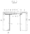
- a locking device which has a bolt lock 5 for locking the active leaf 3 with respect to the door frame 2, a lever operated door lock 6 for regulating the active leaf 3 with respect to the passive leaf 4 and in the lintel area 7 of the door frame 2 an actuating linkage 8 for the active connection of the active leaf 3 and bolt lock 5 of the passive leaf 4 comprises.
- This actuating linkage 8 consists of a push rod 9 in the form of a flat actuating arm, which is pivotally connected at one end about a pivot axis 19 parallel to the wing pivot axes 18 to an abutment 10 fastened in the upper edge region of the active leaf 4.
- a slide 11 is articulated.
- the slider 11 is horizontally displaceably mounted in a longitudinal guide 12 parallel to the camber and serves to actuate the bolt lock 5.
- the bolt lock 5 is composed of a locking pin 13 protruding in the upper area of the passive leaf 4 on the one hand and a web-shaped pin receptacle 14 provided in the door frame 2 on the other hand.
- the pin receptacle 14 has a bolt 15 which engages on the slider 11 to close the front slot opening 16.
- both the passive leaf 4 and the active leaf 3 are locked, the locking pin 13 of the bolt lock 5 engaging in the pin receptacle 14 and being held here by the bolt 15 pushed forward with the slide piece 11 and thus closing the slot opening 16.
- This measure fixes the passive leaf 4 with respect to the door frame 2.
- the active leaf 3 is also locked via the door lock 6 with the passive leaf 4, so that the double-leaf door is securely locked. If the door lock 6 is now opened by actuating the handle 20, the active leaf 3 can swivel open, this swiveling movement being transmitted via the push rod 9 as a longitudinal displacement to the slide 11 guided in the longitudinal guide 12.
- the slider 11 thereby pulls back the bolt 15 of the bolt lock 5 and the slot opening 16 the pin receptacle 14 is released.
- the locking pin 13 can pivot through this release from the pin receptacle 14 when a force is exerted on the passive leaf 4, which means that the passive leaf 4 is unlocked at the same time.
- the actuating linkage 8 of the locking device makes it possible to utilize the pivoting movement of the active leaf 3 for actuating the bolt lock 5 and for locking the passive leaf 4 with respect to the door frame 2.
- the door according to the invention can therefore be operated correctly via the door lock 6 of the active leaf 3 without additional handles for locking or unlocking the passive leaf, but the passive leaf 4 is locked with respect to the door frame 2 and the bolt lock used for this remains essentially invisible.
- the object according to the invention dispenses with any kind of drive rods which are usually also actuated by the door lock.
- the object according to the invention is therefore also extremely well suited for equipping existing systems in the retrofit business with such a positive release or positive lock.
- a prescribed locking device can also be easily attached or integrated when using a closing sequence controller that works mechanically with a push rod and a push element.
- the locking device would also be arranged invisibly within the slide rail.
Landscapes
- Engineering & Computer Science (AREA)
- Mechanical Engineering (AREA)
- Special Wing (AREA)
- Operating, Guiding And Securing Of Roll- Type Closing Members (AREA)
- Specific Sealing Or Ventilating Devices For Doors And Windows (AREA)
- Refrigerator Housings (AREA)
- Wing Frames And Configurations (AREA)
Abstract
Description
- Die Erfindung betrifft eine zweiflügelige Tür, insbesondere Fluchttür, die mit einem Riegelverschluß zum Verriegeln des einen Türflügels, des Standflügels gegenüber dem Türstock oder dgl. und einem Türschloß zur Verriegelung des anderen Türflügels, des Gangflügels gegenüber dem Standflügel und/oder dem Türstock umfassenden Verriegelungsvorrichtung ausgestattet ist.
- Zum Verriegeln zweiflügeliger Türen werden allgemein Verriegelungsvorrichtungen verwendet, die einerseits den Standflügel über eigens betätigbare Stangenverschlüsse mit dem Türstock oder einer türstockfesten Querstrebe oder dgl. und andererseits den Gangflügel über ein drückerbetätigbares Fallenschloß mit dem Standflügel verriegeln. Dadurch müssen die Verschlüsse für beide Türflügel eigene Griffe, Türdrücker oder dgl. aufweisen und zum Entriegeln der Tür ist auch eine Betätigung dieser beiden Türdrücker oder dgl. erforderlich, was bei der Verwendung solcher Türen als Fluchttüren zu unerwünschten Verzögerungen im Panikfall führt. Außerdem ergibt vor allem der Sperrmechanismus für den Standflügel eine recht komplizierte Konstruktion, die den gesamten Bauaufwand der Verriegelungsvorrichtung erhöht und verteuert.
- Gemäß der EP 0 288 454 D1 wurde auch schon eine zweiflügelige Feuer- und Rauchschutztür vorgeschlagene, bei der die gesamte Verriegelungsvorrichtung in Form eines Zweifallenschloßsystemes in dem Gangflügel angeordnet ist, und der Standflügel über den selbst auch gegenüber dem Türstock verriegelbaren Gangflügel fixiert wird. Ein Öffnen des Fallenschlosses bewirkt hier ein gleichzeitiges Freigeben des Gangflügels und des Standflügels. Nachteilig ist, daß sich der Standflügel nur über den Türfalz verriegeln und nicht direkt im Türstock. Im Panikfalle würde ein Versagen des Fallenschlosses jegliches Öffnen der Tür verhindern, was die Gefahr durch die erforderliche Wirkverbindung des Türdrückers einerseits mit der Falle zur Verriegelung des Standflügels und andererseits mit der im Oberkantenbereich des Gangflügels angeordneten Falle zur Verriegelung gegenüber dem Türstock beträchtlich erhöht, als es bei üblichen Fallenschlössern der Fall ist.
- Die DE 43 22 622 C1 beschreibt eine Entriegelungsvorrichtung für eine, einen Gang- und Standflügel aufweisende zweiflügelige Tür, wobei beide Türflügel jeweils mit einem separaten elektromechanischen bzw. elektrohydraulischen Türflügelantrieb ausgestattet sind. Bei den hier automatisch betriebenen Türen muß ebenfalls eine sichere Entriegelung des Stand- und Gangflügels gewährleistet werden. Erreicht wir dieses dadurch, daß direkt durch den Drehflügelantrieb des Gangflügels ein Steuerorgan betätigt wird, welches in Verbindung mit einer Entriegelung auch den Standflügel automatisch entriegelt. Eine Entriegelung geschieht dann automatisch, wenn der Gangflügel begangen wird. Erst wenn der Standflügel auch durch ein Sensorsignal dazu angeregt wird, aus seiner Schließlage heraus zu fahren, öffnet sich auch dieser automatisch, wie bereits vorher der Gangflügel. Das Steuerorgan, welches direkt von dem Drehflügelantrieb gesteuert wird, kann je nach Ausführung des Drehflügelantriebes entweder ein Hydraulikzylinder sein, der direkt in den Kreislauf des hydraulischen Drehflügelantriebes integriert oder nachträglich angebaut wird, oder es kann auch ein Hubmagnet sein, welcher ebenfalls direkt durch den Drehflügelantrieb gesteuert werden kann. Dabei wird bei der Verwendung eines Hubmagneten je nach Funktion der doppelflügeligen Tür z.B. bei einer Panikfunktion so vorzugehen sein, daß im stromlosen Zustand eine sichere Entriegelung des Standflügels gegeben ist, wobei bei einer Feuer- oder einer Rauchschutztür die Funktion anders gelagert ist, nämlich daß der Standflügel und damit auch der Gangflügel verriegelt sind, wenn aufgrund eines Brandes die zweiflügelige Tür einen Brandabschnitt abschließen soll.
- Eine Panikentriegelung wird in der DE 34 36 749 A1 für eine zweiflügelige Tür offenbart, bei der der Standflügel über den Gangflügel verriegelt werden kann. Oberhalb des Türrahmens, nämlich im Türstock ist eine wippenartige Anordnung angebracht, die in der Entriegelungslage des Standflügels auch zwangsläufig den Gangflügel mit entriegelt.
- Ein weiteres Paniköffnungssystem wir in der DE 33 27 210 C2 erläutert. Bei diesem Paniköffnungssystem wird die Rückstellung der Verriegelung von Hand erfolgen müssen. Es besteht aber die Forderung, daß bei Feuer- und Rauchschutztüren eine selbsttätige Rückstellung der Haltesysteme zu erfolgen hat. Dieses System soll deshalb den Nachteil einer elektromagnetischen Verriegelung am Gangflügel aufheben, wenn der Druck auf den Flügel durch die flüchtenden Personen ein Entriegeln der Tür auch bei abgeschaltetem Magneten unmöglich macht. Durch den Elektromagneten kann der Gangflügel der Tür durch Fernbedienung ver- oder entriegelt werden. Im Panikfalle kann dann die flüchtende Person die Tür von außen durch Betätigung des Standflügeldrückers öffnen, was besonders problematisch ist, denn gerade bei Dunkelheit oder bei dichtem Rauch ist eine solche Vorgehensweise enorm erschwert, und eine Öffnung der Tür ist deshalb in aller Regel nicht möglich.
- Eine Zwangsentriegelung für zweiflügelige Türen ist der DE 42 22 751 C2 zu entnehmen. Bei einer Betätigung des Standflügels wird gleichzeitig auch der Gangflügel mit entriegelt. Durch eine Zwangsentriegelung, die sich entweder oberhalb oder unterhalb der Türflügel befinden kann, wird ein federbelastetes Schubglied, das gleichzeitig auch den Gangflügel mit entriegelt, betätigt.
- Der Erfindung liegt deshalb die Aufgabe zugrunde, die aufgezeigten Mängel des Standes der Technik zu beseitigen und eine zweiflügelige Tür der eingangs beschriebenen Art zu schaffen, die sich bei einfacher Bedienung durch ihre Funktionssicherheit und ihr rationelles Konstruktionskonzept auszeichnet.
- Die Erfindung löst diese Aufgabe dadurch, daß eine rein mechanische Vorrichtung verwendet wird, die auf die Benutzung der üblicherweise eingesetzten Treibstangen verzichtet. Dabei wird die Verriegelungsvorrichtung im Sturzbereich des Türstockes oder dgl. Ein Betätigungsgestänge aufweisen, das aus einer an einem Ende um eine zu den Flügelschwenkachsen parallele Schwenkachse schwenkbar am Gangflügel angelenkten Schubstange und eine am anderen Ende der Schubstange angelenkten, in einer sturzparallelen Längsführung verschiebbar geführten Gleitstück besteht, wobei ein Verschlußteil des Riegelverschlusses für den Standflügel mit dem Gleitstück verbunden ist,. Durch den vorgesehenen Riegelverschluß ist der Standflügel gegenüber dem Türstock oder bei einer Tür mit Oberlicht oder dgl. gegenüber dem Kämpfer oder dgl. verriegelbar und ein übliches kostengünstiges Türschloß erlaubt die Verriegelung des Gangflügels gegenüber dem Standflügel, wobei über das Betätigungsgestänge der Riegelverschluß des Standflügels in Abhängigkeit von der Schwenkbewegung des Gangflügels betätigt wird.
- Eine solche Schwenkbewegung wird mittels der Schubstange und dem Gleitstück in eine sturzparallele Hubbewegung umgewandelt, die auf einfache Weise zur Betätigung eines Verschlußteiles für den Riegelverschluß nutzbar ist. Dadurch braucht nun im Standflügel kein händisch betätigbarer Riegelverschluß mehr angeordnet werden und zum Öffnen der zweiflügeligen Tür genügt das Betätigen des Drückers des Türschlosses für den Gangflügel. Die zweiflügelige Tür kann daher wegen der Verriegelung des Standflügels gegenüber dem Türstock oder dgl. sicher verschlossen und dennoch mit nur einem Drücker vollständig geöffnet werden. Darüber hinaus kommt noch hinzu, daß durch die mechanische Wirkverbindung zwischen dem Riegelverschluß des Standflügels und der Schwenkbewegung des Gangflügels ein zwangsweises Öffnen des Riegelverschlusses erfolgt und die gewünschte Funktionssicherheit gewährleistet ist.
- Eine besonders einfache und zweckmäßige Konstruktion ergibt sich, wenn der Riegelverschluß für den Standflügel einerseits aus einem im Oberkantenbereich des Standflügels befestigten, hochragenden Verriegelungszapfen und andererseits aus einer im Türstock oder dgl. vorgesehenen schlitzförmigen Zapfenaufnahme besteht, deren Schlitzöffnung stirnseitig mit einem am Gleitstück angreifenden Riegel verschließbar ist. Dieser mechanische Riegelverschluß bleibt bei geschlossener Tür unsichtbar und bedarf nur sehr einfacher Bauteile, nämlich eines fest montierten Verriegelungszapfens am Standflügel und einer entsprechenden Zapfenaufnahme im Türstock sowie eines am Gleitstück angreifenden Riegels, der vorteilhafterweise längsverstellbar am Gleitstück befestigt ist, aber durchaus auch mit dem Gleitstück hergestellt werden kann.
- Nach einer vorteilhaften Ausgestaltung der Erfindung bildet das Betätigungsgestänge eine Bestandteil einer Türbetätigungsvorrichtung, wie Türschließervorrichtung oder dgl. Das Betätigungsgestänge eignet sich bestens zur Kombination mit einer Türbetätigungsvorrichtung, da die Schubstange nicht nur zum Verschieben des Gleitstückes sondern auch zum Verschwenken des Gangflügels eingesetzt werden kann. Eine einfache Zusatzeinrichtung, beispielsweise eine das Gleitstück im Schließsinn belastende Schließfeder macht aus dem Betätigungsgestänge beim Öffnen der Tür gleichzeitig auch eine Türschließvorrichtung, da eine solche Schließfeder beim Aufschwenken des Gangflügels gespannt wird und dann beim Entspannen, d.h. beim Freiwerden der gespeicherten Energie eine automatische Schließung der Tür mit sich bringt, wobei selbstverständlich ein üblicher Schließfolgeregler für das geordnete Schließen zuerst des Standflügels und dann des Gangflügels sorgen kann. Die Betätigungsvorrichtung läßt sich gemeinsam mit dem Betätigungsgestänge problemlos im Türstockbereich unsichtbar unterbringen, so daß nicht nur eine funktionssichere und aufwandsarme, sondern auch optisch ansprechende Konstruktion gewährleistet ist.
- Es können ohne weiteres auch herkömmliche Türschließer beispielsweise mit einem Gleitschienensystem und darin verschiebbaren Gleitstücken zur Anwendung kommen. Insbesondere zum nachträglichen Ausbau oder zur Vervollständigung einer solchen Tür ist es möglich, nicht innerhalb des Türstockes, sondern außerhalb des Türstockes eine Gleitschiene anzubringen. Diese Gleitschiene beinhaltet neben der Schließfolgeregelvorrichtung auch gleichzeitig die Verriegelungsvorrichtung der erfindungsgemäßen Art.
- Die Erfindung wird anhand eines schematisch dargestellten möglichen Ausführungsbeispieles näher erläutert. Es zeigt:
- Figur 1:
- Eine zweiflügelige Tür in der Draufsicht
- Figur 2:
- Eine teilweise geschnittene zweiflügelige Tür in der Vorderansicht
- In der Figur 1 ist eine zweiflügelige Tür mit ihren beiden Türflügeln, nämlich dem Gangflügel 3 und dem Standflügel 4, dargestellt. Dabei sind sowohl der Gangflügel 3 und der Standflügel 4 über Bänder 17 an dem Türstock 2 drehgelagert befestigt. Ferner ist eine Verriegelungsvorrichtung vorhanden, die einen Riegelverschluß 5 zum Verriegeln des Gangflügels 3 gegenüber dem Türstock 2, ein drückerbetätigbares Türschloß 6 zum Verregeln des Gangflügels 3 gegenüber dem Standflügel 4 sowie im Sturzbereich 7 des Türstockes 2 ein Betätigungsgestänge 8 zur Wirkverbindung von Gangflügel 3 und Riegelverschluß 5 des Standflügels 4 umfaßt. Dieses Betätigungsgestänge 8 besteht aus einer Schubstange 9 in Form eines flachen Betätigungsarmes, die an einem Ende um eine zu den Flügelschwenkachsen 18 parallele Schwenkachse 19 schwenkbar mit einem im Oberkantenbereich des Gangflügels 4 befestigten Widerlager 10 verbunden ist. Am anderen Ende der Schubstange 9 ist ein Gleitstück 11 angelenkt. Das Gleitstück 11 ist in einer sturzparallelen Längsführung 12 horizontal verschiebbar gelagert und dient zur Betätigung des Riegelverschlusses 5. Der Riegelverschluß 5 setzt sich aus einem im oberen Bereich des Standflügels 4 hervorstehenden Verriegelungszapfen 13 einerseits und aus einer im Türstock 2 vorgesehenen stegförmigen Zapfenaufnahme 14 andererseits zusammen. Dabei weist die Zapfenaufnahme 14 einen am Gleitstück 11 angreifenden Riegel 15 zum Verschließen der stirnseitigen Schlitzöffnung 16 auf.
- Bei geschlossener zweiflügeliger Tür sind sowohl der Standflügel 4 und der Gangflügel 3 verriegelt, wobei der Verriegelungszapfen 13 des Riegelverschlusses 5 in die Zapfenaufnahme 14 eingreift und hier durch den mit dem Gleitstück 11 vorgeschobenen, und damit die Schlitzöffnung 16 verschließenden Riegel 15 festgehalten wird. Durch diese Maßnahme wird der Standflügel 4 gegenüber dem Türstock 2 fixiert. Der Gangflügel 3 ist über das Türschloß 6 ebenfalls mit dem Standflügel 4 verriegelt, so daß ein sicherer Verschluß der zweiflügeligen Tür gegeben ist. Wird nun das Türschloß 6 durch Betätigung des Drückers 20 geöffnet, so kann der Gangflügel 3 aufschwenken, wobei diese Schwenkbewegung über die Schubstange 9 als Längsverschiebung auf das in der Längsführung 12 geführte Gleitstück 11 übertragen wird. Das Gleitstück 11 zieht dadurch den Riegel 15 des Riegelverschlusses 5 zurück, und die Schlitzöffnung 16 der Zapfenaufnahme 14 wird freigegeben. Der Verriegelungszapfen 13 kann durch diese Freigabe aus der Zapfenaufnahme 14 herausschwenken, wenn auf den Standflügel 4 eine Kraft ausgeübt wird, was bedeutet, daß der Standflügel 4 gleichzeitig mit entriegelt wird.
- Durch das Betätigungsgestänge 8 der Verriegelungsvorrichtung ist es möglich, die Schwenkbewegung des Gangflügels 3 zur Betätigung des Riegelverschlusses 5 und zur Verriegelung des Standflügels 4 gegenüber dem Türstock 2 auszunutzen. Die erfindungsgemäße Tür läßt sich daher über das Türschloß 6 des Gangflügels 3 einwandfrei betätigen, ohne daß zusätzliche Handgriffe für ein Ver- oder Entriegeln des Standflügels vorgenommen werden müssen, wobei aber der Standflügel 4 gegenüber dem Türstock 2 verriegelt wird, und der dazu eingesetzte Riegelverschluß im wesentlichen unsichtbar bleibt. Gleichzeitig wird durch den erfindungsgemäßen Gegenstand auf jegliche Art von Treibstangen, die üblicherweise durch das Türschloß mit betätigt werden, verzichtet. Somit eignet sich der erfindungsgemäße Gegenstand auch äußerst gut dafür, um im Nachrüstgeschäft bestehende Anlagen mit einer solchen Zwangsentriegelung bzw. Zwangsverriegelung auszustatten.
- Neben den verschiedenen möglichen Ausführungsbeispielen kann auch bei der Verwendung eines Schließfolgereglers, der mechanisch mit einer Schubstange und einem Schubglied arbeitet, eine vorgeschriebene Verriegelungsvorrichtung ohne weiteres mit angebracht oder integriert werden. Dabei würde die Verriegelungsvorrichtung auch unsichtbar innerhalb der Gleitschiene angeordnet sein.
-
- 1
- Zweiflügelige Tür
- 2
- Türstock
- 3
- Standflügel
- 4
- Gangflügel
- 5
- Riegelverschluß
- 6
- Türschloß
- 7
- Sturz
- 8
- Betätigungsgestänge
- 9
- Schubstange
- 10
- Widerlager
- 11
- Gleitstück
- 12
- Längsführung
- 13
- Verriegelungszapfen
- 14
- Zapfenaufnahme
- 15
- Riegel
- 16
- Schlitzöffnung
- 17
- Bänder
- 18
- Schwenkachse
- 19
- Schwenkachse
- 20
- Drücker
Claims (9)
- Zweiflügelige Tür (1), insbesondere Fluchttür, mit einer einen Riegelverschluß zum Verriegeln des einen Türflügels, des Standflügels (3), gegenüber dem Türstock (2) oder dgl. und ein Türschloß (6) zur Verriegelung des anderen Türflügels, des Gangflügels (4), gegenüber dem Standflügel (3) und/oder dem Türstock (2) umfassenden Verriegelungsvorrichtung, dadurch gekennzeichnet, daß die Verriegelungsvorrichtung im Sturzbereich (7) des Türstockes (2) oder dgl. ein Betätigungsorgan (8) aufweist, das vom Gangflügel (4) gesteuert wird und mit/oder in einer sturzparallelen Längsführung (12) und mit einem darin ortsveränderbaren Verschlußteil (15), zur Sperrung und Freigabe des Standflügels (3) zusammenwirkt.
- Zweiflügelige Tür nach Anspruch 1, dadurch gekennzeichnet, daß das Betätigungsorgan (8) aus einer an einem Ende um eine zu den Schwenkachsen (18) parallele Schwenkachse (19) schwenkbar am Gangflügel (4) angelenkten Schubstange (9) und einem am anderen Ende der Schubstange (9) in der Längsführung (12) verschiebbar geführten Gleitstück (11) besteht.
- Zweiflügelige Tür nach den Ansprüchen 1 und 2, dadurch gekennzeichnet, daß das Verschlußteil (15) des Riegelverschlusses (5) mit dem Gleitstück (11) verbunden ist.
- Zweiflügelige Tür nach den Ansprüchen 1 bis 3, dadurch gekennzeichnet, daß der Riegelverschluß (5) für den Standflügel (3) einerseits aus einem im Oberkantenbereich des Standflügels (3) befestigten hochragenden Verriegelungszapfen (13) und andererseits aus einer im Türstock (2) oder dergleichen vorgesehenen schlitzförmigen Zapfenaufnahme (14) besteht, deren Schlitzöffnung (16) mit einem am Gleitstück (11) angreifenden Riegel (15) verschließbar ist.
- Zweiflügelige Tür nach den Ansprüchen 1 oder 2, dadurch gekennzeichnet, daß das Betätigungsorgan (8) ein Bestandteil einer Türbetätigungsvorrichtung, wie Schließfolgeregelung oder dgl. bildet.
- Zweiflügelige Tür nach einem oder mehreren der vorhergehenden Ansprüche, dadurch gekennzeichnet, daß die Verriegelungsvorrichtung unsichtbar eingebaut ist.
- Zweiflügelige Tür nach einem oder mehreren der vorhergehenden Ansprüche, dadurch gekennzeichnet, daß die Verriegelungsvorrichtung in einem Gleitschienensystem für Türschließer integriert ist.
- Zweiflügelige Tür nach einem oder mehreren der vorhergehenden Ansprüche, dadurch gekennzeichnet, daß als Türschließer ein Obentürschließer verwendet wird.
- Zweiflügelige Tür nach einem oder mehreren der vorhergehenden Ansprüche, dadurch gekennzeichnet, daß als Türschließer ein Bodentürschließer verwendet wird.
Priority Applications (3)
| Application Number | Priority Date | Filing Date | Title |
|---|---|---|---|
| DE59506902T DE59506902D1 (de) | 1995-08-17 | 1995-08-17 | Zweiflügelige Tür |
| EP95112045A EP0759493B1 (de) | 1995-08-17 | 1995-08-17 | Zweiflügelige Tür |
| AT95112045T ATE184953T1 (de) | 1995-08-17 | 1995-08-17 | Zweiflügelige tür |
Applications Claiming Priority (1)
| Application Number | Priority Date | Filing Date | Title |
|---|---|---|---|
| EP95112045A EP0759493B1 (de) | 1995-08-17 | 1995-08-17 | Zweiflügelige Tür |
Publications (2)
| Publication Number | Publication Date |
|---|---|
| EP0759493A1 true EP0759493A1 (de) | 1997-02-26 |
| EP0759493B1 EP0759493B1 (de) | 1999-09-22 |
Family
ID=8219492
Family Applications (1)
| Application Number | Title | Priority Date | Filing Date |
|---|---|---|---|
| EP95112045A Expired - Lifetime EP0759493B1 (de) | 1995-08-17 | 1995-08-17 | Zweiflügelige Tür |
Country Status (3)
| Country | Link |
|---|---|
| EP (1) | EP0759493B1 (de) |
| AT (1) | ATE184953T1 (de) |
| DE (1) | DE59506902D1 (de) |
Cited By (1)
| Publication number | Priority date | Publication date | Assignee | Title |
|---|---|---|---|---|
| CN112038896A (zh) * | 2020-09-03 | 2020-12-04 | 鲁特电工股份有限公司 | 一种电力用小型变电站防护室 |
Citations (10)
| Publication number | Priority date | Publication date | Assignee | Title |
|---|---|---|---|---|
| DE52835C (de) * | F. MATHUSE in Berlin, Admiralstrafse 18.' Vom 21. Januar'1890 ab | Selbsttätiger Kantenriegel | ||
| DE701171C (de) * | 1938-01-20 | 1941-01-10 | Karl Geisberger | Verriegelung fuer Doppeltueren von Kaesten o. dgl. |
| GB613748A (en) * | 1946-07-01 | 1948-12-02 | Max Willacy Kuhn | Means for fastening hinged doors and the like |
| DE3327210C2 (de) | 1983-07-28 | 1985-06-05 | Heinrich 3550 Marburg Sälzer | Paniköffnungssystem |
| DE3436749A1 (de) | 1984-07-04 | 1986-01-23 | Franz Dipl.-Ing. 5760 Arnsberg Kraft | Panikentriegelung einer zweifluegeligen tuer |
| EP0288454A2 (de) | 1987-04-23 | 1988-10-26 | Walter Degelsegger | Verriegelungsvorrichtung für zweiflügelige Türen, insbesondere Feuer- und Rauchschutztüren |
| EP0505350A1 (de) * | 1991-03-19 | 1992-09-23 | Manfred Sterrer | Drehscheiben-Schliessfolge- und Verriegelungseinrichtung |
| DE4222751C2 (de) | 1992-07-10 | 1994-05-05 | Dorma Gmbh & Co Kg | Zwangsentriegelung für zweiflügelige Türen |
| DE4322622C1 (de) | 1993-07-07 | 1995-02-02 | Dorma Gmbh & Co Kg | Entriegelungsvorrichtung für eine zweiflügelige, einen Stand- und Gangflügel umfassende Tür |
| DE29503583U1 (de) * | 1995-02-07 | 1995-04-13 | Dorma Gmbh + Co. Kg, 58256 Ennepetal | Schließfolgeregler für eine zweiflügelige Tür |
-
1995
- 1995-08-17 EP EP95112045A patent/EP0759493B1/de not_active Expired - Lifetime
- 1995-08-17 DE DE59506902T patent/DE59506902D1/de not_active Expired - Lifetime
- 1995-08-17 AT AT95112045T patent/ATE184953T1/de not_active IP Right Cessation
Patent Citations (10)
| Publication number | Priority date | Publication date | Assignee | Title |
|---|---|---|---|---|
| DE52835C (de) * | F. MATHUSE in Berlin, Admiralstrafse 18.' Vom 21. Januar'1890 ab | Selbsttätiger Kantenriegel | ||
| DE701171C (de) * | 1938-01-20 | 1941-01-10 | Karl Geisberger | Verriegelung fuer Doppeltueren von Kaesten o. dgl. |
| GB613748A (en) * | 1946-07-01 | 1948-12-02 | Max Willacy Kuhn | Means for fastening hinged doors and the like |
| DE3327210C2 (de) | 1983-07-28 | 1985-06-05 | Heinrich 3550 Marburg Sälzer | Paniköffnungssystem |
| DE3436749A1 (de) | 1984-07-04 | 1986-01-23 | Franz Dipl.-Ing. 5760 Arnsberg Kraft | Panikentriegelung einer zweifluegeligen tuer |
| EP0288454A2 (de) | 1987-04-23 | 1988-10-26 | Walter Degelsegger | Verriegelungsvorrichtung für zweiflügelige Türen, insbesondere Feuer- und Rauchschutztüren |
| EP0505350A1 (de) * | 1991-03-19 | 1992-09-23 | Manfred Sterrer | Drehscheiben-Schliessfolge- und Verriegelungseinrichtung |
| DE4222751C2 (de) | 1992-07-10 | 1994-05-05 | Dorma Gmbh & Co Kg | Zwangsentriegelung für zweiflügelige Türen |
| DE4322622C1 (de) | 1993-07-07 | 1995-02-02 | Dorma Gmbh & Co Kg | Entriegelungsvorrichtung für eine zweiflügelige, einen Stand- und Gangflügel umfassende Tür |
| DE29503583U1 (de) * | 1995-02-07 | 1995-04-13 | Dorma Gmbh + Co. Kg, 58256 Ennepetal | Schließfolgeregler für eine zweiflügelige Tür |
Cited By (1)
| Publication number | Priority date | Publication date | Assignee | Title |
|---|---|---|---|---|
| CN112038896A (zh) * | 2020-09-03 | 2020-12-04 | 鲁特电工股份有限公司 | 一种电力用小型变电站防护室 |
Also Published As
| Publication number | Publication date |
|---|---|
| EP0759493B1 (de) | 1999-09-22 |
| ATE184953T1 (de) | 1999-10-15 |
| DE59506902D1 (de) | 1999-10-28 |
Similar Documents
| Publication | Publication Date | Title |
|---|---|---|
| EP3832055B1 (de) | Verriegelungseinheit für eine schliessanlage einer tür | |
| EP0726379A1 (de) | Schliessfolgeregler für eine zweiflügelige Tür | |
| DE19652601C1 (de) | Ent- und Verriegelung für eine einen Standflügel und einen Gangflügel aufweisende Tür | |
| EP1832700A2 (de) | Verriegelungssystem für eine Tür | |
| EP2264268B2 (de) | Treibriegelschloss | |
| DE102010046402A1 (de) | Arretiereinheit zum Feststellen einer Tür in einer Haltestellung, Türschließsystem mit einer solchen Arretiereinheit und Verfahren zum Betrieb einer solchen Arretiereinheit | |
| EP1066444B1 (de) | Zweiflügelige tür, insbesondere feuerschutztür | |
| DE69608942T2 (de) | Anlage um einen Flügel angelehnt zu halten | |
| EP2339096B1 (de) | Treibstangenschloss mit Panikfunktion und Mehrfachverriegelung | |
| DE19652599C2 (de) | Ent- und Verriegelung für eine einen Standflügel und einen Gangflügel aufweisende Tür | |
| EP0858541B1 (de) | Verriegelungsvorrichtung | |
| DE69609988T2 (de) | Türsicherheitsvorrichtung | |
| DE4222751C2 (de) | Zwangsentriegelung für zweiflügelige Türen | |
| DE4322622C1 (de) | Entriegelungsvorrichtung für eine zweiflügelige, einen Stand- und Gangflügel umfassende Tür | |
| DE102018115985B4 (de) | Schlossgegenkasten für ein Aktivflügelschloss mit Falzluftausgleich | |
| DE8704036U1 (de) | Türschloß mit Verriegelungselement und Hilfsfalle | |
| EP0759493B1 (de) | Zweiflügelige Tür | |
| DE102009031490A1 (de) | Schließfolgeregelung | |
| EP3628801A1 (de) | Schlossvorrichtung für eine tür | |
| EP1801336A1 (de) | Schliessfolgeregelung | |
| AT395630B (de) | Doppelfluegelige brandschutztuer | |
| DE10111732A1 (de) | Schliessfolgeregler für eine zweiflügelige Tür | |
| DE3417054A1 (de) | Treibstangenverschluss fuer den standfluegel von zweifluegeligen tueren, insbesondere selbsttaetig schliessenden feuerschutztueren | |
| AT509508B1 (de) | Mitnehmer zur montage im oberen türfalz eines stehflügels einer zweiflügeligen tür | |
| EP1544396B1 (de) | Vorrichtung zur Schliessfolgeregelung |
Legal Events
| Date | Code | Title | Description |
|---|---|---|---|
| PUAI | Public reference made under article 153(3) epc to a published international application that has entered the european phase |
Free format text: ORIGINAL CODE: 0009012 |
|
| AK | Designated contracting states |
Kind code of ref document: A1 Designated state(s): AT CH DE FR GB IT LI |
|
| GBC | Gb: translation of claims filed (gb section 78(7)/1977) | ||
| 17P | Request for examination filed |
Effective date: 19970128 |
|
| ITCL | It: translation for ep claims filed |
Representative=s name: DE DOMINICIS & MAYER S.R.L. |
|
| EL | Fr: translation of claims filed | ||
| 17Q | First examination report despatched |
Effective date: 19980827 |
|
| GRAG | Despatch of communication of intention to grant |
Free format text: ORIGINAL CODE: EPIDOS AGRA |
|
| GRAG | Despatch of communication of intention to grant |
Free format text: ORIGINAL CODE: EPIDOS AGRA |
|
| GRAH | Despatch of communication of intention to grant a patent |
Free format text: ORIGINAL CODE: EPIDOS IGRA |
|
| ITF | It: translation for a ep patent filed | ||
| GRAH | Despatch of communication of intention to grant a patent |
Free format text: ORIGINAL CODE: EPIDOS IGRA |
|
| GRAA | (expected) grant |
Free format text: ORIGINAL CODE: 0009210 |
|
| AK | Designated contracting states |
Kind code of ref document: B1 Designated state(s): AT CH DE FR GB IT LI |
|
| REF | Corresponds to: |
Ref document number: 184953 Country of ref document: AT Date of ref document: 19991015 Kind code of ref document: T |
|
| REG | Reference to a national code |
Ref country code: CH Ref legal event code: NV Representative=s name: BOVARD AG PATENTANWAELTE Ref country code: CH Ref legal event code: EP |
|
| GBT | Gb: translation of ep patent filed (gb section 77(6)(a)/1977) |
Effective date: 19990923 |
|
| REF | Corresponds to: |
Ref document number: 59506902 Country of ref document: DE Date of ref document: 19991028 |
|
| ET | Fr: translation filed | ||
| PLBE | No opposition filed within time limit |
Free format text: ORIGINAL CODE: 0009261 |
|
| STAA | Information on the status of an ep patent application or granted ep patent |
Free format text: STATUS: NO OPPOSITION FILED WITHIN TIME LIMIT |
|
| 26N | No opposition filed | ||
| REG | Reference to a national code |
Ref country code: GB Ref legal event code: IF02 |
|
| PG25 | Lapsed in a contracting state [announced via postgrant information from national office to epo] |
Ref country code: IT Free format text: LAPSE BECAUSE OF NON-PAYMENT OF DUE FEES;WARNING: LAPSES OF ITALIAN PATENTS WITH EFFECTIVE DATE BEFORE 2007 MAY HAVE OCCURRED AT ANY TIME BEFORE 2007. THE CORRECT EFFECTIVE DATE MAY BE DIFFERENT FROM THE ONE RECORDED. Effective date: 20050817 |
|
| PGFP | Annual fee paid to national office [announced via postgrant information from national office to epo] |
Ref country code: FR Payment date: 20060817 Year of fee payment: 12 |
|
| PGFP | Annual fee paid to national office [announced via postgrant information from national office to epo] |
Ref country code: GB Payment date: 20060824 Year of fee payment: 12 |
|
| REG | Reference to a national code |
Ref country code: CH Ref legal event code: PUE Owner name: BRANDSCHUTZ SYSTEME GMBH Free format text: DORMA GMBH + CO. KG#BRECKERFELDER STRASSE 42-48#58256 ENNEPETAL (DE) -TRANSFER TO- BRANDSCHUTZ SYSTEME GMBH#PRAMWALD 8#4680 HAAG AM HAUSRUCK (AT) |
|
| REG | Reference to a national code |
Ref country code: GB Ref legal event code: 732E |
|
| REG | Reference to a national code |
Ref country code: CH Ref legal event code: PUE Owner name: WALTER DEGELSEGGER Free format text: BRANDSCHUTZ SYSTEME GMBH#PRAMWALD 8#4680 HAAG AM HAUSRUCK (AT) -TRANSFER TO- WALTER DEGELSEGGER#DESSELBRUNN 21#4693 DESSELBRUNN (AT) |
|
| GBPC | Gb: european patent ceased through non-payment of renewal fee |
Effective date: 20070817 |
|
| REG | Reference to a national code |
Ref country code: FR Ref legal event code: TP |
|
| REG | Reference to a national code |
Ref country code: FR Ref legal event code: ST Effective date: 20080430 |
|
| PG25 | Lapsed in a contracting state [announced via postgrant information from national office to epo] |
Ref country code: FR Free format text: LAPSE BECAUSE OF NON-PAYMENT OF DUE FEES Effective date: 20070831 |
|
| PG25 | Lapsed in a contracting state [announced via postgrant information from national office to epo] |
Ref country code: GB Free format text: LAPSE BECAUSE OF NON-PAYMENT OF DUE FEES Effective date: 20070817 |
|
| PGFP | Annual fee paid to national office [announced via postgrant information from national office to epo] |
Ref country code: CH Payment date: 20090827 Year of fee payment: 15 Ref country code: AT Payment date: 20090826 Year of fee payment: 15 |
|
| REG | Reference to a national code |
Ref country code: CH Ref legal event code: PFA Owner name: WALTER DEGELSEGGER Free format text: WALTER DEGELSEGGER#DESSELBRUNN 21#4693 DESSELBRUNN (AT) -TRANSFER TO- WALTER DEGELSEGGER#DESSELBRUNN 21#4693 DESSELBRUNN (AT) |
|
| REG | Reference to a national code |
Ref country code: CH Ref legal event code: PL |
|
| PG25 | Lapsed in a contracting state [announced via postgrant information from national office to epo] |
Ref country code: CH Free format text: LAPSE BECAUSE OF NON-PAYMENT OF DUE FEES Effective date: 20100831 Ref country code: LI Free format text: LAPSE BECAUSE OF NON-PAYMENT OF DUE FEES Effective date: 20100831 |
|
| PG25 | Lapsed in a contracting state [announced via postgrant information from national office to epo] |
Ref country code: AT Free format text: LAPSE BECAUSE OF NON-PAYMENT OF DUE FEES Effective date: 20100817 |
|
| PGFP | Annual fee paid to national office [announced via postgrant information from national office to epo] |
Ref country code: DE Payment date: 20110823 Year of fee payment: 17 |
|
| PG25 | Lapsed in a contracting state [announced via postgrant information from national office to epo] |
Ref country code: DE Free format text: LAPSE BECAUSE OF NON-PAYMENT OF DUE FEES Effective date: 20130301 |
|
| REG | Reference to a national code |
Ref country code: DE Ref legal event code: R119 Ref document number: 59506902 Country of ref document: DE Effective date: 20130301 |