EP0759562A2 - Une méthode et un appareil pour l'imagerie par résonance magnétique - Google Patents
Une méthode et un appareil pour l'imagerie par résonance magnétique Download PDFInfo
- Publication number
- EP0759562A2 EP0759562A2 EP96305556A EP96305556A EP0759562A2 EP 0759562 A2 EP0759562 A2 EP 0759562A2 EP 96305556 A EP96305556 A EP 96305556A EP 96305556 A EP96305556 A EP 96305556A EP 0759562 A2 EP0759562 A2 EP 0759562A2
- Authority
- EP
- European Patent Office
- Prior art keywords
- magnetic resonance
- gradient
- bandwidth
- read
- phase
- Prior art date
- Legal status (The legal status is an assumption and is not a legal conclusion. Google has not performed a legal analysis and makes no representation as to the accuracy of the status listed.)
- Granted
Links
Images


Classifications
-
- G—PHYSICS
- G01—MEASURING; TESTING
- G01R—MEASURING ELECTRIC VARIABLES; MEASURING MAGNETIC VARIABLES
- G01R33/00—Arrangements or instruments for measuring magnetic variables
- G01R33/20—Arrangements or instruments for measuring magnetic variables involving magnetic resonance
- G01R33/44—Arrangements or instruments for measuring magnetic variables involving magnetic resonance using nuclear magnetic resonance [NMR]
- G01R33/48—NMR imaging systems
- G01R33/54—Signal processing systems, e.g. using pulse sequences ; Generation or control of pulse sequences; Operator console
-
- G—PHYSICS
- G01—MEASURING; TESTING
- G01R—MEASURING ELECTRIC VARIABLES; MEASURING MAGNETIC VARIABLES
- G01R33/00—Arrangements or instruments for measuring magnetic variables
- G01R33/20—Arrangements or instruments for measuring magnetic variables involving magnetic resonance
- G01R33/44—Arrangements or instruments for measuring magnetic variables involving magnetic resonance using nuclear magnetic resonance [NMR]
- G01R33/48—NMR imaging systems
- G01R33/54—Signal processing systems, e.g. using pulse sequences ; Generation or control of pulse sequences; Operator console
- G01R33/56—Image enhancement or correction, e.g. subtraction or averaging techniques, e.g. improvement of signal-to-noise ratio and resolution
- G01R33/561—Image enhancement or correction, e.g. subtraction or averaging techniques, e.g. improvement of signal-to-noise ratio and resolution by reduction of the scanning time, i.e. fast acquiring systems, e.g. using echo-planar pulse sequences
- G01R33/5615—Echo train techniques involving acquiring plural, differently encoded, echo signals after one RF excitation, e.g. using gradient refocusing in echo planar imaging [EPI], RF refocusing in rapid acquisition with relaxation enhancement [RARE] or using both RF and gradient refocusing in gradient and spin echo imaging [GRASE]
-
- G—PHYSICS
- G01—MEASURING; TESTING
- G01R—MEASURING ELECTRIC VARIABLES; MEASURING MAGNETIC VARIABLES
- G01R33/00—Arrangements or instruments for measuring magnetic variables
- G01R33/20—Arrangements or instruments for measuring magnetic variables involving magnetic resonance
- G01R33/28—Details of apparatus provided for in groups G01R33/44 - G01R33/64
- G01R33/32—Excitation or detection systems, e.g. using radio frequency signals
- G01R33/36—Electrical details, e.g. matching or coupling of the coil to the receiver
- G01R33/3621—NMR receivers or demodulators, e.g. preamplifiers, means for frequency modulation of the MR signal using a digital down converter, means for analog to digital conversion [ADC] or for filtering or processing of the MR signal such as bandpass filtering, resampling, decimation or interpolation
-
- G—PHYSICS
- G01—MEASURING; TESTING
- G01R—MEASURING ELECTRIC VARIABLES; MEASURING MAGNETIC VARIABLES
- G01R33/00—Arrangements or instruments for measuring magnetic variables
- G01R33/20—Arrangements or instruments for measuring magnetic variables involving magnetic resonance
- G01R33/44—Arrangements or instruments for measuring magnetic variables involving magnetic resonance using nuclear magnetic resonance [NMR]
- G01R33/48—NMR imaging systems
- G01R33/54—Signal processing systems, e.g. using pulse sequences ; Generation or control of pulse sequences; Operator console
- G01R33/543—Control of the operation of the MR system, e.g. setting of acquisition parameters prior to or during MR data acquisition, dynamic shimming, use of one or more scout images for scan plane prescription
-
- G—PHYSICS
- G01—MEASURING; TESTING
- G01R—MEASURING ELECTRIC VARIABLES; MEASURING MAGNETIC VARIABLES
- G01R33/00—Arrangements or instruments for measuring magnetic variables
- G01R33/20—Arrangements or instruments for measuring magnetic variables involving magnetic resonance
- G01R33/44—Arrangements or instruments for measuring magnetic variables involving magnetic resonance using nuclear magnetic resonance [NMR]
- G01R33/48—NMR imaging systems
- G01R33/54—Signal processing systems, e.g. using pulse sequences ; Generation or control of pulse sequences; Operator console
- G01R33/56—Image enhancement or correction, e.g. subtraction or averaging techniques, e.g. improvement of signal-to-noise ratio and resolution
- G01R33/565—Correction of image distortions, e.g. due to magnetic field inhomogeneities
- G01R33/56563—Correction of image distortions, e.g. due to magnetic field inhomogeneities caused by a distortion of the main magnetic field B0, e.g. temporal variation of the magnitude or spatial inhomogeneity of B0
Definitions
- the present invention relates to a magnetic resonance imaging method and system. It finds particular application in conjunction with echo-planar (EPI) and gradient and spin echo (GSE) imaging techniques and will be described with particular reference thereto. However, it is to be appreciated that the present technique is also applicable to other rapid imaging sequences including spin echo and field echo, as well as a multiple-echo sequences.
- EPI echo-planar
- GSE gradient and spin echo
- radio frequency signals have been applied to cause the preferentially aligned dipoles to resonate and emit resonance signals of a characteristic radio frequency.
- the radio frequency magnetic resonance signals from the resonating dipoles are read out for reconstruction into an image representation.
- the resonance signal is commonly refocused into an echo.
- a spin echo is generated by following a radio frequency excitation pulse with a 180° refocusing pulse which causes the resonating spin system to refocus as a spin echo.
- the time between the refocusing pulse and the spin echo is the same as the time between the excitation pulse and the refocusing pulse.
- Other disturbances to the spin system can also be used to induce an echo. For example, reversing the polarity of the magnetic field, particularly the read gradient of the magnetic field, induces a field or gradient echo.
- Various techniques have been developed for causing a plurality of echoes sequentially following a single excitation.
- the echoes may include a series of spin echoes, a series of field echoes, or a mixture of field and spin echoes. See, for example, U.S. Patent No. 4,833,408 of Holland, et al.
- each view of magnetic resonance data is collected during a spin or field echo in the presence of a read gradient that frequency encodes spatial position within the object in the direction of the gradient.
- a series of like acquisitions are repeated, rotating the gradient, but maintaining its amplitude constant with a constant data sampling rate.
- the read gradient is held stationary rather than rotating, but is proceeded by a phase-encode gradient pulse in a direction orthogonal to the read gradient.
- the amplitude of the phase encode gradient was stepped to adjust the phase encoding from view to view, the magnitude of the read-out gradient was held constant with a constant data sampling rate.
- the scheme of data lines with different phase-encodings are typically denoted as k-space data. That is, in k-space, the data line with zero phase-encoding generally extends across the center of k-space.
- Data lines with the phase-encoding gradient stepped in progressive positive steps are generally depicted as being above the centerline of k-space, and data lines with progressive negative phase-encode steps are depicted as below the centerline of k-space.
- k-space has 256, 512, etc. data lines.
- the data lines are typically sampled the same 256, 512, etc. times to make a square k-space matrix that is Fourier transformed into a square image.
- each excitation is followed by a plurality of data acquisitions.
- a series of field echoes are generated by rapidly reversing the read-out gradient, e.g., an oscillating read-out gradient of constant amplitude, to produce a series of data lines in k-space following each excitation or shot. If the oscillating read gradient is fast enough, an entire image of data can be acquired with a single excitation, i.e., a single shot technique.
- each excitation can be followed by a smaller plural number of data acquisition intervals corresponding to a combination of field and spin echoes.
- the spin and field echoes are collected with a common bandwidth or sampling rate, but are sorted into different segments of k-space to improve image quality.
- the first echo following each excitation can be placed in the central portion of k-space which contributes more strongly to the resultant image than the data taken at the maximum and minimum phase encode gradients.
- a common feature of the above-discussed prior art is that they use identical data sampling bandwidths for the data acquisition of all echoes.
- the phase error resulting from the local magnetic field inhomogeneity is more significant between different echoes of a repeated echo sequence.
- spin echoes are relatively insensitive to field inhomogeneities
- field echoes are affected by field inhomogeneities which results in a T 2 * decay of the signal.
- the greater the time interval between the spin and field echoes the greater the phase mismatch between the field and spin echoes due to the T 2 * decay.
- the narrower the read bandwidth of the echoes the more dramatic is the effect of field inhomogeneities.
- the negative effect increases in severity as additional field and spin echo sets are collected following each of a series of 180° inversion pulses.
- post-processing methods exist to correct for some of these phase differences, the methods are not completely reliable and tend to introduce some loss in resolution in the final image.
- the present invention is directed to a new and improved data acquisition technique which overcomes the above-referenced problems and others.
- a method of magnetic resonance imaging is provided. Magnetic resonance is excited in selected dipoles and magnetic resonance echoes are induced. The induced echoes are read out along a first axis in the presence of a read gradient. The magnetic resonance echoes are digitized and demodulated to form digital data lines which are stored and reconstructed by a reconstruction algorithm to generate an image representation. A first of the magnetic resonance echoes is read out with a first sampling rate in the presence of a first read gradient of a first amplitude to generate a first digital data line with a first bandwidth.
- a second magnetic resonance echo is read out with a second sampling rate in the presence of a second read gradient of a second amplitude different from the first to generate a second digital data line of a second bandwidth different from the first bandwidth.
- the digital data lines of the first and second bandwidths are reconstructed to form a common resultant image representation.
- a magnetic resonance imaging system In accordance with another aspect of the present invention, a magnetic resonance imaging system is provided.
- a magnet generates a temporally constant magnetic field through an examination region.
- Gradient magnetic field coils and a gradient magnetic field controller generate at least phase and read magnetic field gradient pulses in orthogonal directions across the examination region.
- a radio frequency pulse controller and a transmitter induce dipoles in the examination region to resonate, such that radio frequency resonance signals are generated.
- a receiver receives and demodulates the radio frequency magnetic resonance signals to produce a series of data lines.
- An analog-to-digital converter is associated with the receiver such that the data lines are digital.
- a data memory stores the digital data lines.
- a reconstruction processor reconstructs the data lines from the data memory into an image representation.
- a read gradient scaler scales the amplitude and width of selected read gradient pulses such that a bandwidth of the radio frequency magnetic resonance signals received during the scaled read gradient is altered.
- a sampling rate control controls a sampling rate of each received radio frequency magnetic resonance signal in accordance with the change in bandwidth.
- One advantage of the present invention is that it opens a whole new avenue of design flexibility for magnetic resonance imaging sequence optimization.
- Another advantage of the present invention is that it reduces T 2 * related phase errors in multiple-echo imaging sequences.
- Another advantage of the present invention resides in the accelerated data acquisition rate.
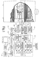
- a main magnetic field control 10 controls superconducting or resistive magnets 12 such that a substantially uniform, temporally constant magnetic field is created along a z-axis through an examination region 14 .
- a magnetic resonance echo means applies a series of radio frequency (RF) and magnetic field gradient pulses to invert or excite magnetic spins, induce magnetic resonance, refocus magnetic resonance, manipulate magnetic resonance, spatially and otherwise encode the magnetic resonance, to saturate spins, and the like to generate magnetic resonance imaging and spectroscopy sequences.
- gradient pulse amplifiers 20 apply current pulses to selected ones or pairs of whole body gradient coils 22 to create magnetic field gradients along x, y, and z-axes of the examination region 14 .
- a digital radio frequency transmitter 24 transmits radio frequency pulses or pulse packets to a whole body RF coil 26 to transmit RF pulses into the examination region.
- a typical radio frequency pulse is composed of a packet of immediately contiguous pulse segments of short duration which taken together achieve a selected magnetic resonance manipulation.
- the RF pulses are used to saturate, excite resonance, invert magnetization, refocus resonance, or manipulate resonance in selected portions of the examination region.
- the resonance signals are commonly picked up by the whole body RF coil 26 .
- local coils are commonly placed contiguous to the selected region.
- an insertable head coil 30 is inserted surrounding a selected brain region at the isocenter of the bore.
- the insertable head coil optionally includes local gradient coils 32 which receive current pulses from the gradient amplifiers 20 to create magnetic field gradients along x, y, and z-axes in the examination region within the head coil.
- a local radio frequency coil 34 is used to excite magnetic resonance and receive magnetic resonance signals emanating from the patient's head.
- a receive-only local radio frequency coil can be used in conjunction with body-coil transmission.
- An RF screen 36 blocks the RF signals from the RF head coil from inducing eddy currents in the gradient coils and the surrounding structures. The resultant radio frequency signals are picked-up by the whole body RF coil 26 , the local RF coil 34 , or other specialized RF coils and demodulated by a receiver 38 .
- a sequence control circuit 40 controls the gradient pulse amplifiers 20 , the transmitter 24 to generate one of a plurality of pulse sequences loaded from a sequence memory, such as the sequence illustrated in FIGURE 2.
- a clock or timing generator 42 controls an excitation RF pulse generator 44 and a refocusing RF pulse generator 46 .
- the resonance excitation pulse generator 44 controls the radio frequency transmitter to cause a resonance excitation RF pulse 50 to be applied to the imaging region.
- the refocusing RF pulse generator 46 causes the radio frequency transmitter to generate a refocusing pulse 52 , e.g., at a time ⁇ after the excitation pulse.
- the excitation pulse followed by a refocusing pulse causes a spin echo 54 to occur a time 2 ⁇ after excitation.
- the refocusing pulse generator 46 further generates one or more additional refocusing pulses 56 at 2 ⁇ time intervals after the preceding refocusing pulse.
- the timing generator 42 also controls a slice select gradient control 60 which controls the gradient amplifiers 20 to cause slice select gradient pulses 62 concurrently with the RF excitation and refocusing pulses.
- the slice select gradients are used in a single or multiple-slice examination procedure to limit the excitation to a single slice.
- a slab selection pulse may be applied to limit excitation to a slab that is several slices in thickness.
- the slab is encoded in three-dimensions with a combination of phase and read gradients.
- the timing control further controls a phase-encode gradient controller 70 and a read gradient control 72 .
- the phase-encode gradient controller 70 causes the gradient amplifiers 20 to cause an initial phase encode gradient 74 with one of a plurality of phase encode gradient amplitude steps.
- the read gradient controller causes a first read gradient 76 which is reversed to form an opposite plurality read gradient 78 .
- the gradient reversal induces first field or gradient echo 80 .
- the read gradient is again reversed to apply a read gradient 82 which is centered about the spin echo 54 .
- the read gradient is reversed again to an opposite polarity read gradient 84 inducing a second field echo 86 .
- phase-encode gradient amplifier applies phase-encode gradients 88 , 90 to change the phase-encoding between the field and spin echoes.
- a phase-unwrapping gradient pulse 92 is equal and opposite to the sum of the phase-encodings applied by phase-encode gradient pulses 74 , 88 , and 90 such that the net phase-encoding is zeroed prior to application of the net refocusing pulse 56 . Thereafter, a like sequence is applied one or more times.
- a bandwidth controller 100 adjusts the bandwidth at which each of the field and spin echoes is collected. More specifically, the bandwidth controller 100 controls a read gradient scaler 102 which scales the read gradient profiles, particularly increases its magnitude and shortens its duration relative to the prior art. The bandwidth controller controls a sampling rate controller 104 which controls the sampling rate at which the field echoes are sampled.
- the sampling rate controller 104 typically adjusts the sampling rate of analog-to-digital converters 106 which digitize the received signal from the field echoes. If the receiver 38 is an analog receiver, the analog-to-digital converters 106 typically follow the receiver. Alternately, the analog-to-digital converters may be disposed between the radio frequency coil and a digital receiver or incorporated within a digital receiver.
- the read gradient scaler 102 doubles the magnitude and halves the width of the profiles of the read gradient pulses 78 and 84 relative to the read gradient pulse 82 applied during the spin echo and the sampling rate controller 104 doubles the sampling rate, e.g., from 32 MHz to 64 MHz. Of course, other proportional adjustments in the read gradient scaling and sampling rates are also contemplated. It is preferred that the area under the field echo and spin echo read gradients remain constant so that the spatial resolution and field-of-view do not change.
- a sorting routine 110 sorts each of the data lines into a data memory 112 . More specifically, the sequence control 40 controls the amplitude of phase-encode gradient pulses 74 and 88 relative to each other such that the spin echo has a phase-encoding near the center of k-space, e.g., adjacent a zero phase-encoding between 1/3 of the maximum negative phase-encoding and 1/3 of the maximum positive phase-encoding.
- phase-encode gradient 74 and 90 are applied such that the field echoes have phase-encoding between the spin echo phase-encodings and the maximum positive and negative phase-encodings, e.g., between the maximum negative phase-encoding and 1/3 of the maximum negative phase-encoding and between the 1/3 of the maximum positive phase-encoding and the maximum positive phase-encoding.
- the phase-encode gradient 74 would be adjusted to cause the first field echo 80 to have a phase-encoding between steps 44 and 128.
- the second phase-encoding gradient would be adjusted to remove about half of the phase-encoding such that the spin echo 54 has a phase encoding between step -42 and step +43.
- the phase-encode gradient 88 may be held constant at the equivalent of -85 phase-encoding steps such that a center 1/3 of k-space 114 is filled in the same order as a top 1/3 of k-space 116 .
- the second phase-encode gradient 88 may be changed such that the spin echo fills its 1/3 of k-space in a different order.
- the phase-encode gradient 90 analogously adjusts the phase-encoding such that the second field echo 86 takes on the phase-encodings in a lower 1/3 of k-space 118 .
- the phase-encode gradient 90 may subtract roughly 85 steps of phase-encoding such that the bottom 1/3 is covered in the same order as the upper and center 1/3, or may be varied to cover the bottom 1/3 of k-space in a different order.
- the read gradient may be reversed a different number of times to provide only a single field echo or more times to provide more than two field echoes contemporaneously with each spin echo.
- the sampling bandwidth and halving the duration of the field echoes twice as many field echoes can be acquired per spin echo with only the prior art degradation caused by T 2 * phase errors.
- the bandwidth still higher four field echoes can be acquired while still improving the phase-error degradation.
- the segmentation of k-space is changed accordingly. Further, in some applications it may be appropriate to increase the bandwidth of the spin echo sampling and reduce the bandwidth of the field echo samplings.
- a reconstruction processor 120 reconstructs the data after phase correction using a two-dimensional Fourier transform reconstruction algorithm into an image representation that is stored in an image memory 122 .
- a video processor 124 retrieves selected portions of the reconstructed image representation and formats it in appropriate format for display on a human-readable monitor 126 , such as a video monitor, active matrix monitor, liquid crystal display, or the like.
- FIGURE 2 describes the invention in terms of a sequence with mixed spin and field echoes, it is to be appreciated that the present invention applies to sequences with one or more field echoes, one or more spin echoes, or combinations thereof.
- the preferred imaging read-out gradient profile amplitudes G rd (p) during data sampling of an echo (p) are not the same for all echoes.
- the data sampling intervals ⁇ t(p) within each echo are different from echo to echo, depending on the read gradient amplitude.
- a number of complex data points N ds sampled at intervals ⁇ t(p) for each echo is constant.
- the data sampling time T ds (p) over complete echo (p) is: T ds (p) N ds ⁇ t(p) where (p) is the echo index.
- the final two-dimensional complex raw data is obtained by combining such digitally-sampled data into the data memory 112 for later image reconstruction.
- phase correction and time shift are applied to the data lines belonging to different segments by a correction circuit 130 .
- the initial imaging excitation by a slice selective RF pulse induces magnetization of a three-dimensional object with a proton nuclear spin density ⁇ (x,y,z).
- R(t,p,q,s) ⁇ ⁇ (x,y,z) ⁇ (Z-s ⁇ z)e i(G rd Xt+ ⁇ B(x,y,z)t+ 2 ⁇ pY FOV )- qTE T 2 dxdy
- t,p,q, and s denote the sampling time, view index, echo number, and slice numbers, respectively
- G rd (p) is a time dependent magnetic field gradient (read-out) during data acquisition of the echo p
- ⁇ B(x,y,z) denotes main field inhomogeneity which includes the contribution of both magnet
- each acquired data line is a discrete digital representation of a continuous reality and can be uniform or non-uniform. Due to the rise time constraint of the gradient system, the read-out gradient may have a non-constant shape over part or all of the data sampling window. The acquired data lines may be non-uniform in areas of non-constant read-out gradient.
- a regridding processor 132 interpolates the non-linear sampled raw data lines to a linear sampled raw data view on a preselected set of uniformly-spaced grid points.
- the data from echoes of different bandwidth is properly time-shifted and phase corrected before the last Fourier transform along the phase encoding direction.
- the present technique can be used with spin echo, field echo, 3D FSE, multiple-shot EPI, GSE, echo-volume imaging, spiral scan and other imaging sequences.
- the read-out gradient sequence can start with a high amplitude short duration high bandwidth read gradient pulse 140 .
- the amplitude of the read gradient pulse reduces and its duration increases proportionately such that the field-of-view remains constant.
- the sampling bandwidth is reduced correspondingly in each field echo, improving the signal-to-noise ratio.
- a center read gradient pulse 150 and a corresponding field echo 152 are at the minimum bandwidth.
- the read-out gradient pulses 154 , 156 ,... start decreasing in duration and increasing in amplitude until a maximum amplitude minimum width read-out gradient pulse 160 occurs contemporaneously with a maximum bandwidth field echo 162 .
- the phase-encode gradients 170 , 172 ,... are again selected such that the data lines from the lowest bandwidth echoes are disposed near the center of k-space with higher bandwidth data lines being disposed progressively towards the edges. This sequence may be analogously adapted to spin echoes as well.
Landscapes
- Physics & Mathematics (AREA)
- Engineering & Computer Science (AREA)
- Signal Processing (AREA)
- High Energy & Nuclear Physics (AREA)
- Condensed Matter Physics & Semiconductors (AREA)
- General Physics & Mathematics (AREA)
- Health & Medical Sciences (AREA)
- General Health & Medical Sciences (AREA)
- Nuclear Medicine, Radiotherapy & Molecular Imaging (AREA)
- Radiology & Medical Imaging (AREA)
- Magnetic Resonance Imaging Apparatus (AREA)
Applications Claiming Priority (2)
| Application Number | Priority Date | Filing Date | Title |
|---|---|---|---|
| US516386 | 1990-04-30 | ||
| US08/516,386 US5602476A (en) | 1995-08-17 | 1995-08-17 | Ultra-fast MR imaging data acquisition scheme using mixed bandwidth data |
Publications (3)
| Publication Number | Publication Date |
|---|---|
| EP0759562A2 true EP0759562A2 (fr) | 1997-02-26 |
| EP0759562A3 EP0759562A3 (fr) | 1997-04-16 |
| EP0759562B1 EP0759562B1 (fr) | 2002-10-16 |
Family
ID=24055348
Family Applications (1)
| Application Number | Title | Priority Date | Filing Date |
|---|---|---|---|
| EP96305556A Expired - Lifetime EP0759562B1 (fr) | 1995-08-17 | 1996-07-29 | Une méthode et un appareil pour l'imagerie par résonance magnétique |
Country Status (4)
| Country | Link |
|---|---|
| US (1) | US5602476A (fr) |
| EP (1) | EP0759562B1 (fr) |
| JP (1) | JPH0956696A (fr) |
| DE (1) | DE69624303T2 (fr) |
Cited By (3)
| Publication number | Priority date | Publication date | Assignee | Title |
|---|---|---|---|---|
| EP1035417A1 (fr) * | 1999-03-08 | 2000-09-13 | Marconi Medical Systems, Inc. | Procédé et dispositif de résonance magnétique |
| FR2898685A1 (fr) * | 2006-03-14 | 2007-09-21 | Centre Nat Rech Scient | Traitement d'image obtenue par resonance magnetique a bandes passantes variables |
| KR20140060239A (ko) * | 2012-11-09 | 2014-05-19 | 지멘스 악티엔게젤샤프트 | 자기 공명 영상의 영상 특성의 자동화 분류를 위한 방법 및 그 자기 공명 장치 |
Families Citing this family (20)
| Publication number | Priority date | Publication date | Assignee | Title |
|---|---|---|---|---|
| JP3496898B2 (ja) * | 1995-03-03 | 2004-02-16 | 株式会社日立メディコ | 核磁気共鳴撮影装置 |
| US6178271B1 (en) | 1996-04-29 | 2001-01-23 | The Mclean Hospital Corporation | Methods and systems for registering image data |
| US5850486A (en) * | 1996-04-29 | 1998-12-15 | The Mclean Hospital Corporation | Registration of image data |
| US6114853A (en) * | 1997-06-25 | 2000-09-05 | Toshiba America Mri, Inc. | NMR methods for qualification of sequence-induced B0 oscillation and correction of the resultant image artifacts in MRI |
| US6339626B1 (en) * | 1998-03-16 | 2002-01-15 | Ge Medical Systems Global Technology Company, Llc | MRI system with fractional decimation of acquired data |
| US6181832B1 (en) | 1998-04-17 | 2001-01-30 | Mclean Hospital Corporation | Methods and systems for removing artifacts introduced by image registration |
| US6239598B1 (en) | 1998-05-08 | 2001-05-29 | The Uab Reasearch Foundation | Process for rapid sample trajectory calibration for magnetic resonance imaging |
| US6263228B1 (en) * | 1998-08-27 | 2001-07-17 | Toshiba America, Mri, Inc. | Method and apparatus for providing separate water-dominant and fat-dominant images from single scan single point dixon MRI sequences |
| US6252400B1 (en) | 1999-03-18 | 2001-06-26 | Picker International, Inc. | Spin and field echo (safe) FSE |
| JP2001000415A (ja) * | 1999-06-24 | 2001-01-09 | Ge Yokogawa Medical Systems Ltd | 勾配磁場印加方法および装置並びに磁気共鳴撮像装置 |
| US6603990B2 (en) | 2001-08-10 | 2003-08-05 | Toshiba America Mri, Inc. | Separation and identification of water and fat MR images at mid-field strength with reduced T2/T2* weighting |
| DE10157540B4 (de) * | 2001-11-23 | 2007-01-11 | Siemens Ag | Doppelechosequenz und Magnetresonanzgerät zum Ausführen der Doppelechosequenz und Verwendung desselben in der Orthopädie |
| US6933720B2 (en) | 2001-12-11 | 2005-08-23 | Toshiba America Mri, Inc. | Sequence preconditioning for ultra-fast magnetic resonance imaging |
| US6879156B1 (en) * | 2002-05-17 | 2005-04-12 | The General Hospital Corporation | Reducing dead-time effect in MRI projection |
| US7378844B2 (en) * | 2004-09-30 | 2008-05-27 | General Electric Company | Magnetic resonance system, receiver & method of generating detecting and digitizing analog MR signals solely within the MR shielded environment |
| CN100365425C (zh) * | 2005-04-30 | 2008-01-30 | 华东师范大学 | 一种具有选择性激发的正负相位组合脉冲的实现方法 |
| CN102141603B (zh) * | 2010-01-28 | 2013-07-31 | 西门子(深圳)磁共振有限公司 | 一种平面回波成像方法和系统 |
| CN103257333B (zh) * | 2012-02-17 | 2016-04-13 | 西门子(深圳)磁共振有限公司 | 一种磁共振成像中的水脂分离成像方法及装置 |
| CN111210484B (zh) * | 2019-12-31 | 2024-04-19 | 上海联影智能医疗科技有限公司 | 医学图像生成方法、模型训练方法、装置及介质 |
| GB2594686B (en) * | 2020-02-28 | 2023-11-29 | Tesla Dynamic Coils BV | MRI apparatus |
Family Cites Families (16)
| Publication number | Priority date | Publication date | Assignee | Title |
|---|---|---|---|---|
| US5168228A (en) * | 1987-05-14 | 1992-12-01 | National Researh Development Corporation | Echo planar imaging systems |
| US4833407A (en) * | 1987-06-24 | 1989-05-23 | Picker International, Inc. | Scan time reduction using conjugate symmetry and recalled echo |
| US4792758A (en) * | 1987-11-19 | 1988-12-20 | Picker International, Inc. | Steady-state echo magnetic resonance imaging |
| US4859945A (en) * | 1988-05-03 | 1989-08-22 | Elscint Ltd. | Optimized signal to noise ratio |
| US4901020A (en) * | 1988-05-30 | 1990-02-13 | Siemens Aktiengesellschaft | Pulse sequence for operating a nuclear magnetic resonance tomography apparatus for producing images with different T2 contrast |
| JPH0252639A (ja) * | 1988-08-15 | 1990-02-22 | Toshiba Corp | 磁気共鳴イメージング装置 |
| US4952876A (en) * | 1988-11-23 | 1990-08-28 | General Electric Company | Variable bandwidth multiecho NMR imaging |
| US4896113A (en) * | 1988-11-25 | 1990-01-23 | General Electric Company | Use of repeated gradient echoes for noise reduction and improved NMR imaging |
| JP2777155B2 (ja) * | 1988-11-30 | 1998-07-16 | 株式会社東芝 | 磁気共鳴映像装置 |
| US4959611A (en) * | 1989-06-29 | 1990-09-25 | Picker International, Inc. | Out-of-slice artifact reduction technique for magnetic resonance imagers |
| DE4024164A1 (de) * | 1989-08-11 | 1991-02-14 | Siemens Ag | Verfahren zur verbesserung des signal-rausch-verhaeltnisses bei einem kernspin-tomographiegeraet |
| US5168226A (en) * | 1991-05-22 | 1992-12-01 | General Electric | Acquisition of multiple images in fast spin echo nmr scans |
| US5270654A (en) * | 1991-07-05 | 1993-12-14 | Feinberg David A | Ultra-fast multi-section MRI using gradient and spin echo (grase) imaging |
| US5189371A (en) * | 1991-08-08 | 1993-02-23 | The Board Of Trustees Of The Leland Stanford Junior University | Method and means for magnetic resonance imaging and spectroscopy using two-dimensional selective adiabatic PI pulses |
| US5348011A (en) * | 1991-11-14 | 1994-09-20 | Picker International, Inc. | Shared excitation phase encode grouping for improved throughput cardiac gated MRI cine imaging |
| US5311133A (en) * | 1992-10-05 | 1994-05-10 | Picker International, Inc. | Concurrent generation of multiple images in fast (TR<T2) scanning sequences |
-
1995
- 1995-08-17 US US08/516,386 patent/US5602476A/en not_active Expired - Fee Related
-
1996
- 1996-07-29 EP EP96305556A patent/EP0759562B1/fr not_active Expired - Lifetime
- 1996-07-29 DE DE69624303T patent/DE69624303T2/de not_active Expired - Fee Related
- 1996-08-13 JP JP8231457A patent/JPH0956696A/ja active Pending
Cited By (6)
| Publication number | Priority date | Publication date | Assignee | Title |
|---|---|---|---|---|
| EP1035417A1 (fr) * | 1999-03-08 | 2000-09-13 | Marconi Medical Systems, Inc. | Procédé et dispositif de résonance magnétique |
| US6255820B1 (en) | 1999-03-08 | 2001-07-03 | Picker International, Inc. | Variable bandwidth MRI data collection |
| FR2898685A1 (fr) * | 2006-03-14 | 2007-09-21 | Centre Nat Rech Scient | Traitement d'image obtenue par resonance magnetique a bandes passantes variables |
| KR20140060239A (ko) * | 2012-11-09 | 2014-05-19 | 지멘스 악티엔게젤샤프트 | 자기 공명 영상의 영상 특성의 자동화 분류를 위한 방법 및 그 자기 공명 장치 |
| US9465094B2 (en) | 2012-11-09 | 2016-10-11 | Siemens Aktiengesellschaft | Method and magnetic resonance device for the automated classification of an image property of a magnetic resonance image |
| KR101676090B1 (ko) | 2012-11-09 | 2016-11-14 | 지멘스 악티엔게젤샤프트 | 자기 공명 영상의 영상 특성의 자동화 분류를 위한 방법 및 그 자기 공명 장치 |
Also Published As
| Publication number | Publication date |
|---|---|
| US5602476A (en) | 1997-02-11 |
| EP0759562A3 (fr) | 1997-04-16 |
| EP0759562B1 (fr) | 2002-10-16 |
| JPH0956696A (ja) | 1997-03-04 |
| DE69624303T2 (de) | 2003-05-22 |
| DE69624303D1 (de) | 2002-11-21 |
Similar Documents
| Publication | Publication Date | Title |
|---|---|---|
| EP0759562B1 (fr) | Une méthode et un appareil pour l'imagerie par résonance magnétique | |
| US5402067A (en) | Apparatus and method for rare echo imaging using k-space spiral coverage | |
| US5151656A (en) | Correction of nmr data acquired by an echo-planar technique | |
| EP0644437B1 (fr) | Correction de la polarité du gradient de lecture dans l'IRM par EPI et GRASE | |
| US5786692A (en) | Line scan diffusion imaging | |
| US5570019A (en) | Method for magnetic resonance spectroscopic imaging with multiple spin-echoes | |
| US6414487B1 (en) | Time and memory optimized method of acquiring and reconstructing multi-shot 3D MRI data | |
| US5825185A (en) | Method for magnetic resonance spin echo scan calibration and reconstruction | |
| US5621321A (en) | Magnetic resonance scan calibration method for ultra-fast image acquisition | |
| EP0582967A1 (fr) | Angiographie RMN utilisant des séquences d'impulsions rapides avec des impulsions de préparation | |
| EP0391515A2 (fr) | Imagerie par résonance magnétique compensée pour des variations erratiques rapides dans le champ magnétique "statique" pendant une séquence unique de l'imagerie par résonance magnétique | |
| EP0366232A2 (fr) | Procédé pour la production d'images en tranches multiples par RMN | |
| US5652516A (en) | Spectroscopic magnetic resonance imaging using spiral trajectories | |
| US5537039A (en) | Virtual frequency encoding of acquired NMR image data | |
| JPH1040365A (ja) | 磁気共鳴映像法および装置 | |
| US5459400A (en) | Method to enhance the sensitivity of MRI for magnetic susceptibility effects | |
| US20050017719A1 (en) | Magnetic resonance tomography method and apparatus with suppression of ambiguity artifacts in spin echo images | |
| US5786693A (en) | Batch multi-volume angiography using magnetic resonance imaging | |
| US4553096A (en) | Nuclear magnetic resonance method and apparatus | |
| US6933720B2 (en) | Sequence preconditioning for ultra-fast magnetic resonance imaging | |
| US5357200A (en) | Magnetic resonance imaging method and apparatus | |
| US6424153B1 (en) | On-the-fly removal of data inconsistency with k-space oversampling and demodulation in MRI acquisitions | |
| US5528144A (en) | Interleaved slab inversion for enhanced throughput in fluid attenuated inversion recovery imaging | |
| EP3803426B1 (fr) | Imagerie par résonance magnétique de temps d'écho nul comportant une séparation des graisses/de l'eau | |
| US5459401A (en) | MRI method for producing images having weak through medium T2 weighing employing a turbo-spin echo sequence |
Legal Events
| Date | Code | Title | Description |
|---|---|---|---|
| PUAI | Public reference made under article 153(3) epc to a published international application that has entered the european phase |
Free format text: ORIGINAL CODE: 0009012 |
|
| AK | Designated contracting states |
Kind code of ref document: A2 Designated state(s): DE FR NL |
|
| PUAL | Search report despatched |
Free format text: ORIGINAL CODE: 0009013 |
|
| AK | Designated contracting states |
Kind code of ref document: A3 Designated state(s): DE FR NL |
|
| 17P | Request for examination filed |
Effective date: 19971003 |
|
| 17Q | First examination report despatched |
Effective date: 19991124 |
|
| RAP1 | Party data changed (applicant data changed or rights of an application transferred) |
Owner name: MARCONI MEDICAL SYSTEMS, INC. |
|
| GRAG | Despatch of communication of intention to grant |
Free format text: ORIGINAL CODE: EPIDOS AGRA |
|
| GRAG | Despatch of communication of intention to grant |
Free format text: ORIGINAL CODE: EPIDOS AGRA |
|
| GRAH | Despatch of communication of intention to grant a patent |
Free format text: ORIGINAL CODE: EPIDOS IGRA |
|
| GRAH | Despatch of communication of intention to grant a patent |
Free format text: ORIGINAL CODE: EPIDOS IGRA |
|
| GRAA | (expected) grant |
Free format text: ORIGINAL CODE: 0009210 |
|
| AK | Designated contracting states |
Kind code of ref document: B1 Designated state(s): DE FR NL |
|
| PG25 | Lapsed in a contracting state [announced via postgrant information from national office to epo] |
Ref country code: NL Free format text: LAPSE BECAUSE OF FAILURE TO SUBMIT A TRANSLATION OF THE DESCRIPTION OR TO PAY THE FEE WITHIN THE PRESCRIBED TIME-LIMIT Effective date: 20021016 Ref country code: FR Free format text: LAPSE BECAUSE OF FAILURE TO SUBMIT A TRANSLATION OF THE DESCRIPTION OR TO PAY THE FEE WITHIN THE PRESCRIBED TIME-LIMIT Effective date: 20021016 |
|
| REF | Corresponds to: |
Ref document number: 69624303 Country of ref document: DE Date of ref document: 20021121 |
|
| NLV1 | Nl: lapsed or annulled due to failure to fulfill the requirements of art. 29p and 29m of the patents act | ||
| EN | Fr: translation not filed | ||
| PLBE | No opposition filed within time limit |
Free format text: ORIGINAL CODE: 0009261 |
|
| STAA | Information on the status of an ep patent application or granted ep patent |
Free format text: STATUS: NO OPPOSITION FILED WITHIN TIME LIMIT |
|
| 26N | No opposition filed |
Effective date: 20030717 |
|
| PG25 | Lapsed in a contracting state [announced via postgrant information from national office to epo] |
Ref country code: DE Free format text: LAPSE BECAUSE OF NON-PAYMENT OF DUE FEES Effective date: 20040203 |