EP0760068B1 - Procede de fabrication de tuyau a structure amelioree - Google Patents
Procede de fabrication de tuyau a structure amelioree Download PDFInfo
- Publication number
- EP0760068B1 EP0760068B1 EP95916216A EP95916216A EP0760068B1 EP 0760068 B1 EP0760068 B1 EP 0760068B1 EP 95916216 A EP95916216 A EP 95916216A EP 95916216 A EP95916216 A EP 95916216A EP 0760068 B1 EP0760068 B1 EP 0760068B1
- Authority
- EP
- European Patent Office
- Prior art keywords
- water
- plastic
- die
- section
- tube
- Prior art date
- Legal status (The legal status is an assumption and is not a legal conclusion. Google has not performed a legal analysis and makes no representation as to the accuracy of the status listed.)
- Expired - Lifetime
Links
Images


Classifications
-
- F—MECHANICAL ENGINEERING; LIGHTING; HEATING; WEAPONS; BLASTING
- F16—ENGINEERING ELEMENTS AND UNITS; GENERAL MEASURES FOR PRODUCING AND MAINTAINING EFFECTIVE FUNCTIONING OF MACHINES OR INSTALLATIONS; THERMAL INSULATION IN GENERAL
- F16L—PIPES; JOINTS OR FITTINGS FOR PIPES; SUPPORTS FOR PIPES, CABLES OR PROTECTIVE TUBING; MEANS FOR THERMAL INSULATION IN GENERAL
- F16L9/00—Rigid pipes
- F16L9/18—Double-walled pipes; Multi-channel pipes or pipe assemblies
-
- B—PERFORMING OPERATIONS; TRANSPORTING
- B29—WORKING OF PLASTICS; WORKING OF SUBSTANCES IN A PLASTIC STATE IN GENERAL
- B29C—SHAPING OR JOINING OF PLASTICS; SHAPING OF MATERIAL IN A PLASTIC STATE, NOT OTHERWISE PROVIDED FOR; AFTER-TREATMENT OF THE SHAPED PRODUCTS, e.g. REPAIRING
- B29C48/00—Extrusion moulding, i.e. expressing the moulding material through a die or nozzle which imparts the desired form; Apparatus therefor
- B29C48/03—Extrusion moulding, i.e. expressing the moulding material through a die or nozzle which imparts the desired form; Apparatus therefor characterised by the shape of the extruded material at extrusion
- B29C48/09—Articles with cross-sections having partially or fully enclosed cavities, e.g. pipes or channels
-
- B—PERFORMING OPERATIONS; TRANSPORTING
- B29—WORKING OF PLASTICS; WORKING OF SUBSTANCES IN A PLASTIC STATE IN GENERAL
- B29C—SHAPING OR JOINING OF PLASTICS; SHAPING OF MATERIAL IN A PLASTIC STATE, NOT OTHERWISE PROVIDED FOR; AFTER-TREATMENT OF THE SHAPED PRODUCTS, e.g. REPAIRING
- B29C48/00—Extrusion moulding, i.e. expressing the moulding material through a die or nozzle which imparts the desired form; Apparatus therefor
- B29C48/03—Extrusion moulding, i.e. expressing the moulding material through a die or nozzle which imparts the desired form; Apparatus therefor characterised by the shape of the extruded material at extrusion
- B29C48/131—Curved articles
-
- B—PERFORMING OPERATIONS; TRANSPORTING
- B29—WORKING OF PLASTICS; WORKING OF SUBSTANCES IN A PLASTIC STATE IN GENERAL
- B29C—SHAPING OR JOINING OF PLASTICS; SHAPING OF MATERIAL IN A PLASTIC STATE, NOT OTHERWISE PROVIDED FOR; AFTER-TREATMENT OF THE SHAPED PRODUCTS, e.g. REPAIRING
- B29C48/00—Extrusion moulding, i.e. expressing the moulding material through a die or nozzle which imparts the desired form; Apparatus therefor
- B29C48/25—Component parts, details or accessories; Auxiliary operations
- B29C48/88—Thermal treatment of the stream of extruded material, e.g. cooling
- B29C48/90—Thermal treatment of the stream of extruded material, e.g. cooling with calibration or sizing, i.e. combined with fixing or setting of the final dimensions of the extruded article
-
- B—PERFORMING OPERATIONS; TRANSPORTING
- B29—WORKING OF PLASTICS; WORKING OF SUBSTANCES IN A PLASTIC STATE IN GENERAL
- B29C—SHAPING OR JOINING OF PLASTICS; SHAPING OF MATERIAL IN A PLASTIC STATE, NOT OTHERWISE PROVIDED FOR; AFTER-TREATMENT OF THE SHAPED PRODUCTS, e.g. REPAIRING
- B29C48/00—Extrusion moulding, i.e. expressing the moulding material through a die or nozzle which imparts the desired form; Apparatus therefor
- B29C48/25—Component parts, details or accessories; Auxiliary operations
- B29C48/88—Thermal treatment of the stream of extruded material, e.g. cooling
- B29C48/911—Cooling
- B29C48/9115—Cooling of hollow articles
-
- B—PERFORMING OPERATIONS; TRANSPORTING
- B29—WORKING OF PLASTICS; WORKING OF SUBSTANCES IN A PLASTIC STATE IN GENERAL
- B29C—SHAPING OR JOINING OF PLASTICS; SHAPING OF MATERIAL IN A PLASTIC STATE, NOT OTHERWISE PROVIDED FOR; AFTER-TREATMENT OF THE SHAPED PRODUCTS, e.g. REPAIRING
- B29C48/00—Extrusion moulding, i.e. expressing the moulding material through a die or nozzle which imparts the desired form; Apparatus therefor
- B29C48/25—Component parts, details or accessories; Auxiliary operations
- B29C48/88—Thermal treatment of the stream of extruded material, e.g. cooling
- B29C48/90—Thermal treatment of the stream of extruded material, e.g. cooling with calibration or sizing, i.e. combined with fixing or setting of the final dimensions of the extruded article
- B29C48/904—Thermal treatment of the stream of extruded material, e.g. cooling with calibration or sizing, i.e. combined with fixing or setting of the final dimensions of the extruded article using dry calibration, i.e. no quenching tank, e.g. with water spray for cooling or lubrication
Definitions
- This invention relates generally to an improved construction of extruded plastic pipe, and more particularly to a process for forming pipe of this improved construction.
- Plastic pipe has found a variety of uses especially relating to drainage.
- One of the concerns in the manufacture of plastic pipe is the amount of raw materials consumed and the resultant weight of the finished product.
- 121.91 cm (48) interior diameter solid wall plastic pipe weighs approximately 2.98 kg per cm (200 Ibs per foot).
- plastic pipe having cavities or apertures formed therein when the pipe is viewed in cross-section, weighs approximately 0.45 kg per cm (30 lbs per linear foot).
- extruded plastic pipe is formed on a production line having a variety of specific machines incorporated into the manufacturing process.
- One of the first machines is an extruder.
- Plastic powder, or more preferably pellets, is fed through the extruder where it is subjected to high temperatures such that the plastic melts.
- the plasticized plastic then proceeds through a feed tube, at the end of which the plastic enters into a typically drum shaped die.
- At the front of the die is the specific cross-section profile to be extruded.
- calibrating or calibration fingers or bullets which assist in maintaining the desired cross-sectional form which has been extruded.
- These calibration fingers are part of a manifold assembly. The rest of the manifold assembly extends from above the die as well as beyond the calibration fingers.
- plastic pipe is manufactured using a former or forming head.
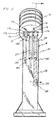
- Fig. 1 is a side view of a die and die post assembly with a manifold assembly secured thereto in an operative position for use in accordance with the process of making the pipe construction embodying the present invention.
- Fig. 2 is a front elevational view of a die and die post assembly in which the die will extrude the wall of a plastic pipe having apertures formed therein, specifically 8 small generally triangular shaped elongate apertures as well as 3 larger generally circular shaped elongate apertures.
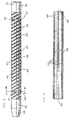
- Fig. 3 is a side elevational view of the calibration finger first section associated with the process embodying the present invention.
- Fig. 4 is a side elevational view of the intermediate tube which is used in the process associated with the preferred embodiment of the invention and is inserted within the calibration finger first section shown in Fig. 3.
- Fig. 5 is a vertical sectional view taken on a greatly enlarged scale along line 5-5 of Fig. 3, however, this particular view shows the calibration finger first section as assembled, thereby disclosing both the outer shell as well as the presence of the intermediate tube.
- Fig. 5A is a vertical sectional view taken on a greatly enlarged scale and similar to Fig. 5, however, this particular view shows one of the endmost calibration finger first section as assembled.
- Fig. 5B is a vertical sectional view taken on a greatly enlarged scale and similar to Figs. 5 and 5A, however, this particular view shows the other endmost calibration finger first section as assembled.
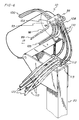
- Fig. 6 is a perspective view on a greatly enlarged scale taken from the top of the die of Fig. 1.
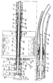
- Fig. 7 is a vertical cross-sectional view on an enlarged scale taken along line 7-7 of Fig. 2.
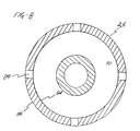
- Fig. 8 is a vertical cross-sectional view on a greatly enlarged scale taken along line 8-8 of Fig. 1.
- Fig. 1 discloses the manifold assembly associated with the process embodying the present invention generally disclosed by the numeral 10.
- the manifold assembly extends through a die 15.
- the die 15, which is drum shaped and has first and second ends, is supported on a die post assembly 20.
- the die and die post are of the type found in plastic extrusion manufacture.
- the preferred embodiment of pipe fabricated by the process of this invention utilizes a side fed spiral feed die, although it could use a side fed spider die.
- the improved manifold calibration fingers 16 are located where bullets or calibration fingers of the prior art have been located, namely, at the second end of the die where the plastic is extruded therefrom.
- Fig. 2 discloses the presence of a die head 17.
- Die heads are well known in the conventional extrusion art. However, this particular die head discloses the presence of 8 small triangular sections 17b and 3 larger circular sections 17a. The circular sections or gaps are of a first size, and the generally triangular section or gaps are of a second size. Both types of die gaps may also be referred to as die openings or die cuts.
- the plastic flows through the die head through these gaps or sections 17a and 17b respectively. Additionally, it will be noted that air vents 17c are located near the center of each of the triangular shapes.
- the die head and calibrating fingers cooperate to form the extrusion of a pipe wall component having a plurality of elongate apertures formed therein when the pipe wall is viewed in cross-section.
- Extending through the die and die head 17 is a portion 12 of the die manifold assembly 10 to which the calibration fingers are physically secured. This portion of the die manifold assembly 10 is shown at the left-most side of the die head 17 and extends some distance from the drum-shaped die, as will be discussed below.
- the calibration finger 16 associated with manifold 10 shown in its complete assembly, as can be appreciated from a comparison with Fig. 1.
- the calibration finger 16 associated with the method of this invention is formed having a first section 25 and a second section 26.
- the first section or tubular member 25 is shown secured by itself to the portion of the die manifold assembly 10 used in the method of this invention, which portion passes through the die 15 at the center portion of the die head 17 in Fig. 2.
- the first tubular member 25 is formed. in the preferred embodiment of pipe made using the process of the invention, having a tubular outer shell 27.
- the tubular outer shell 27 has a first end as well as a second end, 28 and 29 respectively.
- the outer shell 27 is formed having an outer surface 30 with this outer surface 30 having formed therein a first radial groove 33.
- Formed in the first radial groove are a plurality of first section apertures 35.
- a second radial groove 37 is formed having a plurality of second section apertures 39 formed therein.
- the tubular outer shell is preferably formed having a first finger end 40, a finger shell 42, and a second finger end 44. As shown in Fig. 7, these three pieces are components of the tubular outer shell and are secured to each other by respective brass connecting rings 48.
- Each connecting ring 48 is merely a ring with a threaded outer surface which engages with a portion of the inner surface of the finger shell 42.
- a threaded portion of the inner surface of first finger end 40 also engages with the connecting ring 48, with that first finger end inner surface being 52.
- a threaded portion of the inner surface of second finger end 44 also engages with the connecting ring 48. with that second finger end inner surface being 53.
- the first finger end is tapered towards the die head. This permits an easier initial flow of the heated plastic over the calibration finger 16 as the plastic exits the die head 17.
- the outer surface 30 of tubular outer shell 27 also preferably has formed therein a spiral groove 55. It should also be appreciated that the spiral groove intersects with both the first radial groove and the second radial groove. It will also be appreciated from a comparison of Figs. 3 and 5 that the outer shell of the first section 25 of the centralmost set of tubes is preferably formed having two relatively flat surface portions 60 and two curved surface portions 62. whereas the outer two sets of tubes have a flat surface only with respect to their inner side wall as can be seen in Figs. 5A and 5B respectively.
- the intermediate tube 64 shown in Fig. 4 also has a first end 65 and a second end 66, and an inner surface 68 as can be appreciated from Fig. 5 as well as an outer surface 69 as can be appreciated from both Figs. 4 and 5.
- a plurality of generally longitudinally extending channels 70 are formed in the outer surface 69 of intermediate tube 64. In the pipe wall formed using the method of this invention, there are six such water receiving channels 70.
- Fig. 5 shows a vertical cross-sectional view on a greatly enlarged scale wherein the intermediate tube is positioned so as to be encircled by the tubular outer shell 27.
- the various water receiving channels 70 may be seen to become enclosed such that they permit the passage of water in a first direction through the die and towards the second section.
- the flow rate is 15,1 - 18,9 litres (4-5 gallons) of water per minute per each set of tubes.
- the presence of the cool water in the six channels helps to cool the tubular outer shell in the presence of the hot plastic.
- the first tubular member 25 also has a plurality of radially extending channels 72 which extend from the inner surface 68 of intermediate tube 64 to the apertures in either radial groove 33 or 37.
- the inner surfaces 64 of the intermediate tube 64 help to define a channel through which a vacuum is pulled.
- the tubular outer shell has the intermediate tube placed therein. then the appropriate holes are drilled through both the tubular outer shell and the intermediate tube.
- the tubular outer shell and intermediate tube are welded, with the inner surface of the outer shell 27 being welded to the outer surface 69.
- a 2.4 mm (3/32") diameter hole is drilled, a 2.4 mm (3/32") outer diameter aluminum tube with a 1.6 mm (1/16") hole is press fit into the 2.4 mm (3/32”) hole until it reaches the inner surface 68.
- This process is repeated until the desired number of channels exist, which as stated above with reference to Fig. 5 is six.
- the tops of the tubes can be filed off and each respective radially extending channel 72 sealed in place with an appropriate sealant.
- the radial groove is placed on the outer shell after the aforementioned welding and drilling have occurred, but before the insertion of the tubes which make the radially extending channel 72.
- the finger shell 42 is approximately 45.72 cm (18") long in the machine used in the process associated with the preferred embodiment of the invention and has an outer diameter of approximately 3.18 cm (2 1/2").
- the center of the first radial groove is 3.18 cm (2 1/2") from the junction of the finger first end and finger shell.
- the second radial groove is approximately 4.0 cm (1 9/16") from the junction of the second finger end and finger shell.
- the spiral groove is 2.4 mm (3/32") wide and has a 2.54 (1") pitch double lead over the entire 45.72 cm (18").
- the radial grooves are 2.4 mm (3/32").
- the various longitudinally extending channels 70 are formed having a radius of 7.9 mm (5/16").
- each of the slots are formed being 6.4 mm (1/4") from the high point of the radius.
- the intermediate tube is approximately 41.91 cm (16 1/2") long and has an outer diameter such that it fits the inner diameter of the outer shell.
- both the outer shell and the intermediate tube are fabricated from aluminum.
- the second tubular member 26 also fabricated of aluminum, comprises a first end 80 and a second end 82 as well as an inner surface 84 and an outer surface 86.
- the longitudinal shape of the second tubular member 26 corresponds to the shape of the plastic product to be produced. Where as here the fabrication system is designed to produce circular plastic pipe, the longitudinal shape of the second section 26 is curved.
- the second tubular member 26 also has a plurality of apertures 88 formed therein with these apertures extending between the inner surface 84 and the outer surface 86 of the second tubular member 26.
- the second end of the tubular outer shell 27 of the first tubular member 25 is attached to the curved member first end 80.
- first tubular member is of a first length and the second tubular member is of a second length with this second length being longer than the first length.
- the second tubular member measures 106,7 cm (42") in length, with the first 7,6 cm (3") being straight.
- the diameter of the curved member apertures are greater than the diameter of the first member apertures, primarily because the curved member apertures facilitate the flow of water therethrough while the first member apertures are used to facilitate the pulling of a vacuum. The vacuum assists in stabilizing the shape of the plastic as it is extruded.
- the die head first end or rear face 93 has secured thereto a rear manifold tube housing 95, with this securing preferably being accomplished by four screws.
- this rear manifold tube housing comprises three components 95a. 95b, and 95c respectively.
- manifold tube housing 0-rings 96a, 96b, and 96c are positioned adjacent the corresponding rear manifold tube housing component.
- a TEFLON insulative tube 98 connects the interior of the die at the die head rear face 93 with a low pressure air inlet line 99.
- the air which enters the die through this line is ultimately emitted through apertures 17c in the die head and help to cool the plastic triangular walls as well as to exert outward pressure on the plastic to support the cavity and consequently prevent its collapse.
- the pressure is approximately 4,39 to 8,79 g/cm 2 (1-2 ounces per sq inch).
- a water inlet line with one tube for each manifold calibration finger is secured to the rear manifold tube housing.
- This water inlet line 100 permits cool water to be introduced into the manifold assembly.
- a rear vacuum pipe 103 extends from the rear manifold tube housing 95 and connects to a rear vacuum line 105.
- a water expulsion pipe 108 also extends from the rear manifold tube housing 95 with each water expulsion pipe 108 being connected to the water expulsion outlet line first section 110. While the rear vacuum pipe and water expulsion pipe are preferably formed of metal, the rear vacuum line as well as the water expulsion outlet line first section are of plastic composition.
- Each of the water expulsion outlet line first sections 110 connect to a water ejector 112. It has been found that a well ejector package sold by Teel Water Systems as a heavy duty shallow well ejector works quite well to facilitate the removal of water through the manifold following its circulation therethrough.
- the various water ejectors 112 are secured to a water ejector mounting plate 113 which is part of the die post assembly 20.
- respective water expulsion inlet lines 115 are secured at the water ejector mounting plate to be secured to the water ejector 112.
- respective water expulsion outlet line second sections 120 are secured at the water ejector mounting plate to the water ejector. In actual operation.
- FIG. 7 shows a water expulsion port 125 through which the water passes as it is drawn through the calibration finger and secured manifold assembly and then flows through the water expulsion outlet line first sections.
- the water enters the water expulsion port 125 from the inner manifold tube 130 which is connected to the proximal end 92 of the second component 90.
- rear manifold tube housing component 95b is a vacuum port 135.
- the rear manifold tube housing component 95b is preferably welded to vacuum tube 140.
- rear manifold tube housing 95c is preferably welded to outer manifold tube 150.
- rear manifold tube housing component 95a is preferably screwed onto inner manifold tube.
- the distal end of the vacuum tube 140 is held in frictional engagement by the inner surface 68 of the intermediate tube 64 of first section 25.
- the rear vacuum line and rear vacuum pipe 103 permit a vacuum to draw inwardly through the apertures in the radial grooves.
- Each of inner manifold tube 130, vacuum tube 140 and outer manifold tube 150 is preferably fabricated from stainless steel.
- a water inlet port 145 through which the water enters the rear manifold tube housing 95c through water inlet line 100.
- the water thus flows through respective outer manifold tubes 150.
- a housing connector 155 secures the rear manifold tube housing to a manifold mounting plate 160 which in turn is secured to the die head first end or rear face 93 by appropriate fasteners 163.
- die manifold tube 165 extends through the die itself, it has therein the outer manifold tube 150 through which cool water is flowing in a first direction, vacuum tube 140 through which a vacuum is being pulled in the opposite direction to the flow of the cool water, and inner manifold tube 130 through which warm water is also being pulled in that second direction thereafter exiting through the water expulsion lines.
- the outermost surface of each set of tubes 150, 140, and 130 respectively, that being in the preferred embodiment of the invention the outer surface of tube 150, is spaced a first distance from the respective die manifold tube.
- a preferably hex shaped structure 175 which is placed so as to aid in the support and stabilization of the outer manifold tube 150.
- This hex shaped structure 175 can be appreciated as being positioned adjacent mandrel extension tube 185 of the die. which mandrel extension tube which in turn is secured at the front face of the die head at die head apertures 187, which are preferably spanner wrench holes. Mandrel extension tube is screw threaded into a mandrel extension component of the die, with the mandrel extension of the type known in the art. The space between the inner surface of the die manifold tube 165 and the exterior surface of outer manifold tube 150 forms a venting channel 152.
- the method of this invention has the manifold assembly vented to atmosphere by the cooperation of venting channel 152, venting channel outlet 153 and enclosed common airspace 154.
- the venting channel outlet is just a single aperture in the first end of the die, even though there would be three venting channels as in the embodiment of the manifold assembly shown in the drawings.
- the plurality of venting channels associated with each of the sets of tubes preferably converge near the rear interior of the die so as to form a single enclosed common airspace. More preferably, this enclosed common airspace is directly adjacent the venting channel outlet.
- proximal tip 40 and die head 17 are spaced apart a second distance.
- the venting to atmosphere extends from the approximate 3,2 mm (1/8") space between the proximal tip 40 and the die head 17 to the first end of said die with the portion of the venting channel between the die manifold tube and the outermost surface of each set of tubes being only about 1,6 mm (1/16").
- the die is assembled so as to encompass the portion of the manifold assembly shown and discussed above with respect to Fig. 7. When finished it resembles the left-most portion of the die head as seen in Fig. 2.
- the first section 25 is then slid over the secured die manifold assembly 10.
- the first finger threads 190 are then secured to the threaded terminal corresponding terminal end of the outer die manifold tube.
- Helping to maintain a good seal are a first pair of O-rings 192 placed within appropriate grooves on the first finger end inner surface 52 as shown in Fig. 7.
- the first tubular member then is positioned as shown in the middle of die head 1".
- the second tubular member at its first end 80 has a quick release female mechanism of the type well known in pipe art.
- this quick release mechanism is a 2,54 cm (1") brass, straight through flow valve manufactured by Parker-Hanifin, which mechanism joins with the quick release male mechanism 195 positioned at the second end 66 of the intermediate tube 64.
- the flat sections 60 on each of the calibration fingers are parallel to a flat section on an adjacent calibration finger.
- a second pair of 0-rings 198 are found in appropriate grooves on the inner surface 68.
- the presence of the atmospheric vent is extremely important. Initially the machine did not utilize this feature and the hot plastic, in effect, was sucked down into the space between the proximal end of the calibration finger and the die head where it clogged the extrusion operation. The addition of the atmospheric vent more than remedied the situation. Instead of clogging, the plastic easily flowed over the outer surfaces of the calibration fingers.
- the cooling water passes through the water inlet tube 150 and the water receiving channels 70 within each manifold calibration finger while a vacuum is pulled through the middle manifold tube 140 and through the radially extending channels 72 in the first section. Still further, water flows from the water receiving channels into the second section 26 and thereafter through the apertures 88 in the second tubular member onto the outer surface 86 of such calibration finger. The water thus flows between the outer surface of the second section and the extruded plastic which surrounds the calibration finger when the plastic is being extruded so as to cool the extruded plastic pipe. The water is deposited within the cavity of the extruded plastic.
- the process of this invention also has the plastic wall component wound about a machine known as a former until the first end wall of the wall component is directly adjacent the second end wall of the wall component.
- a water cooled side wall guide preferably fabricated from aluminum and secured to the former, stabilizes the first end wall by cooling it.
- a ceramic heater attached to the die post assembly heats, or more accurately reheats, the second end wall.
- the adjacent wall components then have their respective end walls fused together.
- As the end walls fuse together preferably three TEFLON rollers roll the seam down.
- the method includes the additional step of applying water to the outer surface of the now tubular plastic pipe.
- a last cloth is draped over the pipe to assist in drying the pipe surface.
Landscapes
- Engineering & Computer Science (AREA)
- Mechanical Engineering (AREA)
- Physics & Mathematics (AREA)
- Thermal Sciences (AREA)
- General Engineering & Computer Science (AREA)
- Extrusion Moulding Of Plastics Or The Like (AREA)
- Rigid Pipes And Flexible Pipes (AREA)
Claims (6)
- Procédé pour former un tuyau en matière plastique comprenant les étapes consistant à :(a) faire s'écouler de la matière plastique chaude à travers une filière et extruder ultérieurement la matière plastique à travers une tête de filière afin de former un composant à parois extrudées comportant des première et seconde parois d'extrémité, ladite tête de filière ayant formé dans celles-ci une pluralité de premiers intervalles dimensionnés et une pluralité de seconds intervalles dimensionnés, chacun desdits seconds intervalles dimensionnés ayant une ouverture placée dans celui-ci, ladite filière étant fixée à un ensemble de collecteur, ledit ensemble de collecteur comprenant des ensembles de tuyaux placés au centre les uns par rapport aux autres, chaque ensemble de tuyaux comprenant un tuyau d'entrée d'eau, un tuyau à travers lequel un vide est tiré et un tuyau de retour d'eau, chaque dit ensemble étant positionné longitudinalement à l'intérieur d'un tuyau collecteur de filière respectif, la surface la plus à l'extérieur de chaque dit ensemble de tuyaux étant espacée sur une première distance dudit tuyau collecteur de filière respectif, chacun desdits tuyaux collecteurs de filière respectif s'étendant à travers la filière,(b) faire circuler de l'air à une pression comprise dans l'intervalle allant de 4,39 à 8,79 gm par cm carré (1 à 2 onces par pouce carré) à travers les ouvertures de la tête de filière dans la même direction que celle où le plastique est extrudé,(c) extruder la matière plastique sur au moins deux doigts d'étalonnage qui sont fixés à la filière, chacun desdits doigts d'étalonnage ayant une partie proximale adjacente à ladite tête de filière, ladite partie proximale de chacun desdits doigts d'étalonnage étant espacée sur une seconde distance de ladite tête de filière, chacun desdits doigts d'étalonnage comportant une première section ayant une surface extérieure, ladite première section ayant : 1) au moins un canal de réception d'eau raccordé audit tuyau d'entrée d'eau ; 2) un canal raccordé audit tuyau à travers lequel un vide est tiré ; et 3) ledit tuyau de retour d'eau étant positionné au centre de ladite surface extérieure de la première section, ladite première section ayant formé dans celle-ci des ouvertures raccordées audit canal raccordé audit tube à travers lequel un vide est tiré, chacun desdits doigts d'étalonnage ayant une seconde section de doigts d'étalonnage ayant une surface extérieure et un canal intérieur, ladite seconde section ayant ledit tuyau de retour d'eau positionné au centre de ladite surface extérieure de la seconde section, l'extrémité distale dudit tuyau de retour d'eau s'étendant au-delà de l'extrémité distale de ladite seconde section, ladite seconde section ayant formé dans celle-ci des ouvertures raccordées audit canal intérieur,(d) faire s'écouler l'eau à travers le canal de réception d'eau dans une première direction, ladite eau s'écoulant à travers ladite section et dans ladite seconde section et ainsi à travers les ouvertures de ladite seconde section sur la surface extérieure de chacun des doigts d'étalonnage de la seconde section de façon à s'écouler entre la surface extérieure de la seconde section et ledit plastique extrudé,(e) tirer un vide à travers les tuyaux respectifs et les canaux respectifs dans l'ensemble collecteur, ledit vide tirant la matière plastique extrudée vers le bas sur la surface extérieure de la première section de chacun des doigts d'étalonnage et,(f) faire monter l'eau à un certain niveau à l'intérieur de ladite matière plastique extrudée qui est au-dessus de l'extrémité distale du tuyau de retour d'eau de sorte que ladite eau s'écoule dans le tuyau de retour d'eau et s'écoule à travers ledit ensemble collecteur dans une seconde direction.
- Procédé selon la revendication 1, incluant l'étape supplémentaire consistant à enrouler le composant à parois extrudées jusqu'à ce que la première paroi soit adjacente à la seconde paroi et soit fusionnée avec celle-ci.
- Procédé selon la revendication 1 ou 2, comprenant l'étape supplémentaire consistant à amener ledit ensemble collecteur à la pression atmosphérique.
- Procédé selon la revendication 1, 2 ou 3, comprenant l'étape supplémentaire consistant à appliquer l'eau à la surface extérieure de la matière plastique après qu'elle soit extrudée.
- Procédé pour former des tuyaux en matière plastique comprenant les étapes consistant à :(a) extruder la matière plastique à travers une tête de filière sur une pluralité de doigts d'étalonnage, chacun des doigts d'étalonnage ayant de l'eau circulant à travers ceux-ci dans à la fois des première et seconde directions et un vide tiré, la matière plastique, lorsqu'extrudée, formant un composant à parois ayant des première et seconde parois d'extrémité et une pluralité de cavités de première dimension et de seconde dimension,(b) faire circuler simultanément l'air à travers la tête de la filière et dans les cavités de la seconde dimension,(c) tirer un vide à travers chacun des doigts d'étalonnage avec les canaux formés dans chaque doigt d'étalonnage qui s'étendent vers la surface extérieure de chaque doigt d'étalonnage, ledit vide tirant la matière plastique extrudée vers le bas sur la surface extérieure du doigt d'étalonnage,(d) amener l'eau qui circule dans la première direction à circuler à travers les ouvertures dans les doigts d'étalonnage et à circuler entre chaque surface extérieure du doigt d'étalonnage et la matière plastique extrudée pour refroidir la matière plastique extrudée,(e) enrouler le composant à parois extrudées jusqu'à ce que la première paroi d'extrémité soit directement adjacente à la seconde paroi d'extrémité et fusionne avec ladite première paroi d'extrémité, et(f) appliquer l'eau à la surface extérieure de la matière plastique après qu'elle soit extrudée.
- Procédé selon la revendication 5, qui comprend l'étape consistant à amener ledit ensemble de collecteur à la pression atmosphérique.
Applications Claiming Priority (3)
| Application Number | Priority Date | Filing Date | Title |
|---|---|---|---|
| US22454994A | 1994-04-07 | 1994-04-07 | |
| PCT/US1995/004266 WO1995027867A1 (fr) | 1994-04-07 | 1995-04-07 | Procede de fabrication de tuyau a structure amelioree |
| US224549 | 1998-12-31 |
Publications (3)
| Publication Number | Publication Date |
|---|---|
| EP0760068A4 EP0760068A4 (fr) | 1997-01-14 |
| EP0760068A1 EP0760068A1 (fr) | 1997-03-05 |
| EP0760068B1 true EP0760068B1 (fr) | 1999-01-07 |
Family
ID=22841167
Family Applications (1)
| Application Number | Title | Priority Date | Filing Date |
|---|---|---|---|
| EP95916216A Expired - Lifetime EP0760068B1 (fr) | 1994-04-07 | 1995-04-07 | Procede de fabrication de tuyau a structure amelioree |
Country Status (6)
| Country | Link |
|---|---|
| EP (1) | EP0760068B1 (fr) |
| AT (1) | ATE175482T1 (fr) |
| CA (1) | CA2187324A1 (fr) |
| DE (1) | DE69507140T2 (fr) |
| GR (1) | GR3029576T3 (fr) |
| WO (1) | WO1995027867A1 (fr) |
Family Cites Families (5)
| Publication number | Priority date | Publication date | Assignee | Title |
|---|---|---|---|---|
| US3668288A (en) * | 1968-11-18 | 1972-06-06 | Keiichi Takahashi | Method for making thermoplastic synthetic resin hollow structure articles |
| DE1816374B1 (de) * | 1968-12-21 | 1971-01-21 | Manfred Hawerkamp | Wickelhohlprofil aus thermoplastischem Kunststoff zur Herstellung von Rohren,Platten,Behaeltern oder Hohlkoerpern |
| DE2308418B2 (de) * | 1972-06-21 | 1976-04-08 | Petzetakis, Aristovoulos George, Moschaton, Piräus (Griechenland) | Verfahren und vorrichtung zum herstellen eines insbesondere grosskalibrigen rohres aus thermoplastischem kunststoff |
| GB8602950D0 (en) * | 1986-02-06 | 1986-03-12 | Cadbury Ltd | Extrusion die |
| US5261988A (en) * | 1989-09-22 | 1993-11-16 | George A. Petzetakis | Making large-diameter pipe |
-
1995
- 1995-04-07 WO PCT/US1995/004266 patent/WO1995027867A1/fr not_active Ceased
- 1995-04-07 CA CA002187324A patent/CA2187324A1/fr not_active Abandoned
- 1995-04-07 AT AT95916216T patent/ATE175482T1/de not_active IP Right Cessation
- 1995-04-07 DE DE69507140T patent/DE69507140T2/de not_active Expired - Fee Related
- 1995-04-07 EP EP95916216A patent/EP0760068B1/fr not_active Expired - Lifetime
-
1999
- 1999-03-04 GR GR990400660T patent/GR3029576T3/el unknown
Also Published As
| Publication number | Publication date |
|---|---|
| DE69507140D1 (de) | 1999-02-18 |
| GR3029576T3 (en) | 1999-06-30 |
| EP0760068A4 (fr) | 1997-01-14 |
| CA2187324A1 (fr) | 1995-10-19 |
| EP0760068A1 (fr) | 1997-03-05 |
| WO1995027867A1 (fr) | 1995-10-19 |
| DE69507140T2 (de) | 1999-08-19 |
| ATE175482T1 (de) | 1999-01-15 |
Similar Documents
| Publication | Publication Date | Title |
|---|---|---|
| US4377545A (en) | Method of making corrugated reinforced thermoplastic pipe | |
| JPH031140B2 (fr) | ||
| US5505897A (en) | Method for forming a pipe | |
| CN110328824B (zh) | 双层共挤机头模具 | |
| EP0760068A1 (fr) | Procede de fabrication de tuyau a structure amelioree | |
| US5513974A (en) | Manifold assembly with atmospheric vent | |
| EP0918614B1 (fr) | Procede et dispositif d'extrusion | |
| US5513975A (en) | Pipe extrusion die head manifold assembly | |
| KR100614687B1 (ko) | 내 마찰층을 갖는 다공관 제조장치 | |
| MXPA96004639A (en) | Process for the formation of better construction pipeline | |
| MXPA96004640A (en) | Method for the formation of better construction pipe | |
| CN114750392B (zh) | 降密度生物全降解薄膜挤出成型机 | |
| US20060115549A1 (en) | Internal bubble cooling unit for extruded thin wall thermoplastic sheet | |
| EP0754116B1 (fr) | Tige d'etalonnage de tubulure amelioree | |
| WO1995027611A1 (fr) | Ensemble tubulure amelioree pour la production de tuyaux thermoplastiques | |
| KR20020021661A (ko) | 합성수지 나선관 제조용 다중 프로파일과 그 제조방법 및이를 이용한 합성수지 나선관 | |
| KR100821647B1 (ko) | 보온재가 내장되고 이음새가 없는 다중관 및 그 제조장치및 제조방법 | |
| CN110815768A (zh) | 一种内螺旋流道pe水管生产用管材挤出机及其工作方式 | |
| KR950005723B1 (ko) | 합성수지재 2중관의 성형방법 및 장치 | |
| US20250387964A1 (en) | Multiplexed extrusion system | |
| KR100622355B1 (ko) | 폴리에틸렌 다공관, 그의 제조방법 및 제조장치 | |
| MXPA96004642A (en) | Best multiple assembly | |
| CN217573985U (zh) | 气辅冷却成型的pvc给水管材高速挤出模具 | |
| RU53620U1 (ru) | Головка экструдера для формования труб (варианты) | |
| MXPA96004636A (en) | Best multiple calibration finger |
Legal Events
| Date | Code | Title | Description |
|---|---|---|---|
| A4 | Supplementary search report drawn up and despatched | ||
| AK | Designated contracting states |
Kind code of ref document: A4 Designated state(s): AT BE CH DE DK ES FR GB GR IE IT LI NL PT SE |
|
| PUAI | Public reference made under article 153(3) epc to a published international application that has entered the european phase |
Free format text: ORIGINAL CODE: 0009012 |
|
| 17P | Request for examination filed |
Effective date: 19961104 |
|
| AK | Designated contracting states |
Kind code of ref document: A1 Designated state(s): AT BE CH DE DK ES FR GB GR IE IT LI NL PT SE |
|
| RHK1 | Main classification (correction) |
Ipc: F16L 9/18 |
|
| 17Q | First examination report despatched |
Effective date: 19970919 |
|
| GRAG | Despatch of communication of intention to grant |
Free format text: ORIGINAL CODE: EPIDOS AGRA |
|
| GRAG | Despatch of communication of intention to grant |
Free format text: ORIGINAL CODE: EPIDOS AGRA |
|
| GRAH | Despatch of communication of intention to grant a patent |
Free format text: ORIGINAL CODE: EPIDOS IGRA |
|
| GRAH | Despatch of communication of intention to grant a patent |
Free format text: ORIGINAL CODE: EPIDOS IGRA |
|
| GRAA | (expected) grant |
Free format text: ORIGINAL CODE: 0009210 |
|
| RIN1 | Information on inventor provided before grant (corrected) |
Inventor name: TSIGOPOULOS, DIMITRIS Inventor name: MARTIN, LARRY, L. Inventor name: WISE, JOHN |
|
| AK | Designated contracting states |
Kind code of ref document: B1 Designated state(s): AT BE CH DE DK ES FR GB GR IE IT LI NL PT SE |
|
| PG25 | Lapsed in a contracting state [announced via postgrant information from national office to epo] |
Ref country code: SE Free format text: THE PATENT HAS BEEN ANNULLED BY A DECISION OF A NATIONAL AUTHORITY Effective date: 19990107 Ref country code: NL Free format text: LAPSE BECAUSE OF FAILURE TO SUBMIT A TRANSLATION OF THE DESCRIPTION OR TO PAY THE FEE WITHIN THE PRESCRIBED TIME-LIMIT Effective date: 19990107 Ref country code: LI Free format text: LAPSE BECAUSE OF FAILURE TO SUBMIT A TRANSLATION OF THE DESCRIPTION OR TO PAY THE FEE WITHIN THE PRESCRIBED TIME-LIMIT Effective date: 19990107 Ref country code: ES Free format text: THE PATENT HAS BEEN ANNULLED BY A DECISION OF A NATIONAL AUTHORITY Effective date: 19990107 Ref country code: CH Free format text: LAPSE BECAUSE OF FAILURE TO SUBMIT A TRANSLATION OF THE DESCRIPTION OR TO PAY THE FEE WITHIN THE PRESCRIBED TIME-LIMIT Effective date: 19990107 Ref country code: BE Free format text: LAPSE BECAUSE OF FAILURE TO SUBMIT A TRANSLATION OF THE DESCRIPTION OR TO PAY THE FEE WITHIN THE PRESCRIBED TIME-LIMIT Effective date: 19990107 Ref country code: AT Free format text: LAPSE BECAUSE OF FAILURE TO SUBMIT A TRANSLATION OF THE DESCRIPTION OR TO PAY THE FEE WITHIN THE PRESCRIBED TIME-LIMIT Effective date: 19990107 |
|
| REF | Corresponds to: |
Ref document number: 175482 Country of ref document: AT Date of ref document: 19990115 Kind code of ref document: T |
|
| REG | Reference to a national code |
Ref country code: CH Ref legal event code: EP |
|
| REF | Corresponds to: |
Ref document number: 69507140 Country of ref document: DE Date of ref document: 19990218 |
|
| REG | Reference to a national code |
Ref country code: IE Ref legal event code: FG4D |
|
| ITF | It: translation for a ep patent filed | ||
| PG25 | Lapsed in a contracting state [announced via postgrant information from national office to epo] |
Ref country code: PT Free format text: LAPSE BECAUSE OF FAILURE TO SUBMIT A TRANSLATION OF THE DESCRIPTION OR TO PAY THE FEE WITHIN THE PRESCRIBED TIME-LIMIT Effective date: 19990407 Ref country code: IE Free format text: LAPSE BECAUSE OF NON-PAYMENT OF DUE FEES Effective date: 19990407 Ref country code: DK Free format text: LAPSE BECAUSE OF FAILURE TO SUBMIT A TRANSLATION OF THE DESCRIPTION OR TO PAY THE FEE WITHIN THE PRESCRIBED TIME-LIMIT Effective date: 19990407 |
|
| ET | Fr: translation filed | ||
| NLV1 | Nl: lapsed or annulled due to failure to fulfill the requirements of art. 29p and 29m of the patents act | ||
| REG | Reference to a national code |
Ref country code: CH Ref legal event code: PL |
|
| PLBE | No opposition filed within time limit |
Free format text: ORIGINAL CODE: 0009261 |
|
| STAA | Information on the status of an ep patent application or granted ep patent |
Free format text: STATUS: NO OPPOSITION FILED WITHIN TIME LIMIT |
|
| 26N | No opposition filed | ||
| REG | Reference to a national code |
Ref country code: IE Ref legal event code: MM4A |
|
| REG | Reference to a national code |
Ref country code: GB Ref legal event code: IF02 |
|
| PGFP | Annual fee paid to national office [announced via postgrant information from national office to epo] |
Ref country code: GB Payment date: 20020411 Year of fee payment: 8 |
|
| PGFP | Annual fee paid to national office [announced via postgrant information from national office to epo] |
Ref country code: FR Payment date: 20020416 Year of fee payment: 8 |
|
| PGFP | Annual fee paid to national office [announced via postgrant information from national office to epo] |
Ref country code: GR Payment date: 20020426 Year of fee payment: 8 |
|
| PGFP | Annual fee paid to national office [announced via postgrant information from national office to epo] |
Ref country code: DE Payment date: 20020624 Year of fee payment: 8 |
|
| PG25 | Lapsed in a contracting state [announced via postgrant information from national office to epo] |
Ref country code: GB Free format text: LAPSE BECAUSE OF NON-PAYMENT OF DUE FEES Effective date: 20030407 |
|
| PG25 | Lapsed in a contracting state [announced via postgrant information from national office to epo] |
Ref country code: DE Free format text: LAPSE BECAUSE OF NON-PAYMENT OF DUE FEES Effective date: 20031101 |
|
| PG25 | Lapsed in a contracting state [announced via postgrant information from national office to epo] |
Ref country code: GR Free format text: LAPSE BECAUSE OF NON-PAYMENT OF DUE FEES Effective date: 20031104 |
|
| GBPC | Gb: european patent ceased through non-payment of renewal fee |
Effective date: 20030407 |
|
| PG25 | Lapsed in a contracting state [announced via postgrant information from national office to epo] |
Ref country code: FR Free format text: LAPSE BECAUSE OF NON-PAYMENT OF DUE FEES Effective date: 20031231 |
|
| REG | Reference to a national code |
Ref country code: FR Ref legal event code: ST |
|
| PG25 | Lapsed in a contracting state [announced via postgrant information from national office to epo] |
Ref country code: IT Free format text: LAPSE BECAUSE OF NON-PAYMENT OF DUE FEES Effective date: 20050407 |