EP0760287A2 - Tête à jet d'encre, substrat pour tête à jet d'encre, cartouche à jet d'encre et dispositif à jet d'encre - Google Patents
Tête à jet d'encre, substrat pour tête à jet d'encre, cartouche à jet d'encre et dispositif à jet d'encre Download PDFInfo
- Publication number
- EP0760287A2 EP0760287A2 EP96113819A EP96113819A EP0760287A2 EP 0760287 A2 EP0760287 A2 EP 0760287A2 EP 96113819 A EP96113819 A EP 96113819A EP 96113819 A EP96113819 A EP 96113819A EP 0760287 A2 EP0760287 A2 EP 0760287A2
- Authority
- EP
- European Patent Office
- Prior art keywords
- ink
- substrate
- ink jet
- converting elements
- electrothermal converting
- Prior art date
- Legal status (The legal status is an assumption and is not a legal conclusion. Google has not performed a legal analysis and makes no representation as to the accuracy of the status listed.)
- Granted
Links
- 239000000758 substrate Substances 0.000 title claims abstract description 69
- 238000007599 discharging Methods 0.000 claims abstract description 27
- 239000000976 ink Substances 0.000 claims description 161
- 229910052710 silicon Inorganic materials 0.000 claims description 11
- 229910052737 gold Inorganic materials 0.000 claims description 4
- 229910001080 W alloy Inorganic materials 0.000 claims description 3
- 239000007788 liquid Substances 0.000 description 22
- XUIMIQQOPSSXEZ-UHFFFAOYSA-N Silicon Chemical compound [Si] XUIMIQQOPSSXEZ-UHFFFAOYSA-N 0.000 description 9
- 238000009826 distribution Methods 0.000 description 9
- 239000010703 silicon Substances 0.000 description 9
- 239000000463 material Substances 0.000 description 7
- 238000002203 pretreatment Methods 0.000 description 6
- 238000000034 method Methods 0.000 description 5
- 229910052751 metal Inorganic materials 0.000 description 4
- 239000002184 metal Substances 0.000 description 4
- 239000004033 plastic Substances 0.000 description 4
- 229920003023 plastic Polymers 0.000 description 4
- XSQUKJJJFZCRTK-UHFFFAOYSA-N Urea Chemical compound NC(N)=O XSQUKJJJFZCRTK-UHFFFAOYSA-N 0.000 description 3
- 239000000919 ceramic Substances 0.000 description 3
- 239000003086 colorant Substances 0.000 description 3
- 239000000428 dust Substances 0.000 description 3
- 239000007787 solid Substances 0.000 description 3
- 239000000126 substance Substances 0.000 description 3
- 239000002023 wood Substances 0.000 description 3
- 238000007664 blowing Methods 0.000 description 2
- 238000010586 diagram Methods 0.000 description 2
- 238000001914 filtration Methods 0.000 description 2
- PCHJSUWPFVWCPO-UHFFFAOYSA-N gold Chemical compound [Au] PCHJSUWPFVWCPO-UHFFFAOYSA-N 0.000 description 2
- 239000010931 gold Substances 0.000 description 2
- 230000010354 integration Effects 0.000 description 2
- 238000009828 non-uniform distribution Methods 0.000 description 2
- 238000001454 recorded image Methods 0.000 description 2
- UMGDCJDMYOKAJW-UHFFFAOYSA-N thiourea Chemical compound NC(N)=S UMGDCJDMYOKAJW-UHFFFAOYSA-N 0.000 description 2
- 235000017166 Bambusa arundinacea Nutrition 0.000 description 1
- 235000017491 Bambusa tulda Nutrition 0.000 description 1
- 241001330002 Bambuseae Species 0.000 description 1
- 241000283690 Bos taurus Species 0.000 description 1
- RYGMFSIKBFXOCR-UHFFFAOYSA-N Copper Chemical compound [Cu] RYGMFSIKBFXOCR-UHFFFAOYSA-N 0.000 description 1
- CBENFWSGALASAD-UHFFFAOYSA-N Ozone Chemical compound [O-][O+]=O CBENFWSGALASAD-UHFFFAOYSA-N 0.000 description 1
- 235000015334 Phyllostachys viridis Nutrition 0.000 description 1
- IGUHATROZYFXKR-UHFFFAOYSA-N [W].[Ir] Chemical compound [W].[Ir] IGUHATROZYFXKR-UHFFFAOYSA-N 0.000 description 1
- 239000011358 absorbing material Substances 0.000 description 1
- 230000001133 acceleration Effects 0.000 description 1
- 229910052782 aluminium Inorganic materials 0.000 description 1
- XAGFODPZIPBFFR-UHFFFAOYSA-N aluminium Chemical compound [Al] XAGFODPZIPBFFR-UHFFFAOYSA-N 0.000 description 1
- -1 aluminum and copper Chemical class 0.000 description 1
- 239000011425 bamboo Substances 0.000 description 1
- 238000009835 boiling Methods 0.000 description 1
- 230000005587 bubbling Effects 0.000 description 1
- 239000004202 carbamide Substances 0.000 description 1
- 239000003795 chemical substances by application Substances 0.000 description 1
- 229910052802 copper Inorganic materials 0.000 description 1
- 239000010949 copper Substances 0.000 description 1
- 238000005260 corrosion Methods 0.000 description 1
- 230000007797 corrosion Effects 0.000 description 1
- 230000003247 decreasing effect Effects 0.000 description 1
- 238000001514 detection method Methods 0.000 description 1
- 238000009792 diffusion process Methods 0.000 description 1
- 230000000694 effects Effects 0.000 description 1
- 230000005611 electricity Effects 0.000 description 1
- 238000002474 experimental method Methods 0.000 description 1
- 239000004744 fabric Substances 0.000 description 1
- 238000005187 foaming Methods 0.000 description 1
- 238000010438 heat treatment Methods 0.000 description 1
- 239000010985 leather Substances 0.000 description 1
- 239000007769 metal material Substances 0.000 description 1
- 150000002739 metals Chemical class 0.000 description 1
- 230000003287 optical effect Effects 0.000 description 1
- 230000002093 peripheral effect Effects 0.000 description 1
- 239000011120 plywood Substances 0.000 description 1
- 230000002265 prevention Effects 0.000 description 1
- 238000011084 recovery Methods 0.000 description 1
- 150000003839 salts Chemical class 0.000 description 1
- 230000003068 static effect Effects 0.000 description 1
- 229920001059 synthetic polymer Polymers 0.000 description 1
- 238000005406 washing Methods 0.000 description 1
Images


Classifications
-
- B—PERFORMING OPERATIONS; TRANSPORTING
- B41—PRINTING; LINING MACHINES; TYPEWRITERS; STAMPS
- B41J—TYPEWRITERS; SELECTIVE PRINTING MECHANISMS, i.e. MECHANISMS PRINTING OTHERWISE THAN FROM A FORME; CORRECTION OF TYPOGRAPHICAL ERRORS
- B41J2/00—Typewriters or selective printing mechanisms characterised by the printing or marking process for which they are designed
- B41J2/005—Typewriters or selective printing mechanisms characterised by the printing or marking process for which they are designed characterised by bringing liquid or particles selectively into contact with a printing material
- B41J2/01—Ink jet
- B41J2/015—Ink jet characterised by the jet generation process
- B41J2/04—Ink jet characterised by the jet generation process generating single droplets or particles on demand
- B41J2/045—Ink jet characterised by the jet generation process generating single droplets or particles on demand by pressure, e.g. electromechanical transducers
- B41J2/05—Ink jet characterised by the jet generation process generating single droplets or particles on demand by pressure, e.g. electromechanical transducers produced by the application of heat
-
- B—PERFORMING OPERATIONS; TRANSPORTING
- B41—PRINTING; LINING MACHINES; TYPEWRITERS; STAMPS
- B41J—TYPEWRITERS; SELECTIVE PRINTING MECHANISMS, i.e. MECHANISMS PRINTING OTHERWISE THAN FROM A FORME; CORRECTION OF TYPOGRAPHICAL ERRORS
- B41J2/00—Typewriters or selective printing mechanisms characterised by the printing or marking process for which they are designed
- B41J2/005—Typewriters or selective printing mechanisms characterised by the printing or marking process for which they are designed characterised by bringing liquid or particles selectively into contact with a printing material
- B41J2/01—Ink jet
- B41J2/135—Nozzles
- B41J2/14—Structure thereof only for on-demand ink jet heads
- B41J2/14016—Structure of bubble jet print heads
- B41J2/1408—Structure dealing with thermal variations, e.g. cooling device, thermal coefficients of materials
-
- B—PERFORMING OPERATIONS; TRANSPORTING
- B41—PRINTING; LINING MACHINES; TYPEWRITERS; STAMPS
- B41J—TYPEWRITERS; SELECTIVE PRINTING MECHANISMS, i.e. MECHANISMS PRINTING OTHERWISE THAN FROM A FORME; CORRECTION OF TYPOGRAPHICAL ERRORS
- B41J2/00—Typewriters or selective printing mechanisms characterised by the printing or marking process for which they are designed
- B41J2/005—Typewriters or selective printing mechanisms characterised by the printing or marking process for which they are designed characterised by bringing liquid or particles selectively into contact with a printing material
- B41J2/01—Ink jet
- B41J2/135—Nozzles
- B41J2/14—Structure thereof only for on-demand ink jet heads
- B41J2/14016—Structure of bubble jet print heads
- B41J2/14145—Structure of the manifold
-
- B—PERFORMING OPERATIONS; TRANSPORTING
- B41—PRINTING; LINING MACHINES; TYPEWRITERS; STAMPS
- B41J—TYPEWRITERS; SELECTIVE PRINTING MECHANISMS, i.e. MECHANISMS PRINTING OTHERWISE THAN FROM A FORME; CORRECTION OF TYPOGRAPHICAL ERRORS
- B41J2/00—Typewriters or selective printing mechanisms characterised by the printing or marking process for which they are designed
- B41J2/005—Typewriters or selective printing mechanisms characterised by the printing or marking process for which they are designed characterised by bringing liquid or particles selectively into contact with a printing material
- B41J2/01—Ink jet
- B41J2/135—Nozzles
- B41J2/14—Structure thereof only for on-demand ink jet heads
- B41J2002/14387—Front shooter
Definitions
- the present invention relates to an ink jet head, a substrate for ink jet head, an ink jet cartridge, and an ink jet apparatus.
- the ink jet recording apparatus conducts recording with a non-impact recording system.
- the ink jet recording apparatus has characteristics of high speed in recording, possibility of recording on various recording mediums, and generation of no or little noise. Because of such characteristics, ink jet apparatuses are widely used as a recording mechanism in printers, word processors, facsimiles, copying machines, and so forth.
- a typical ink jet recording method employs an electrothermal converting element, and conducts recording by discharging fine liquid droplets through a fine discharge opening onto a recording paper sheet.
- the ink jet recording head generally comprises an ink-ejecting device for forming liquid droplets and an ink-supplying system for supplying ink to the ink-ejecting device.
- an ink jet recording head which has an electrothermal converting element in a pressurizing chamber discharges recording liquid droplets by bubbling pressure generated by foaming or boiling of the recording liquid caused by thermal energy given by electric pulses in accordance with recording signals.
- the ink jet printer is a superior recording system as mentioned above.
- it involves a problem that the recorded image depends on a temperature of the ink jet recording head.
- the quantity of ink discharge varies with the temperature of the recording head, resulting in a larger quantity of ink discharge at a higher ambient temperature as is well known.
- the temperature of the recording head becomes higher during recording, which varies the quantity of ink discharge to cause irregularity of printing density due to the temperature difference between at the beginning of printing and in the course of printing.
- one method is elevation of the head temperature to a certain level by reference to the temperature information derived from one or more detection means such as diode sensors provided in the ink jet recording head.
- Another method is control of the recording liquid around the electrothermal converting element by application of small pulses not causing recording liquid discharge immediately before each discharge.
- Fig. 9 is a front view of a substrate of an ink jet recording head of a prior art.
- the substrate carrying thereon electrothermal converting elements is usually made from a highly thermal conductive silicon.
- the heat generated at the portion A is transferred to the portion B through the portions P and P'. Therefore, owing to low thermal conductivity from A to B, heat distribution is liable to become nonuniform in the ink jet recording head.
- ink jet recording head electric energy caused by applied pulses is converted by an electrothermal converting element into thermal energy.
- the thermal energy is not only converted to kinetic energy for discharging ink droplets but also released to the open air, transferred to ink, and remains in the ink jet recording head. The remaining heat is released later to the open air.
- a problem arises in usual printing in which ink droplets are discharged by continuous application of high frequency electric pulses to electrothermal converting elements. Because relaxation time for releasing the remaining heat is longer than cycle time of ink discharge, the heat is accumulated in the recording head and raises the temperature of the recording head. The accumulated heat causes the problem as below.
- the rise of temperature of an ink jet recording head causes change of the ink discharge rate, giving difference of record density between start of printing and just before end of printing.
- frequency and timing of ink discharge varies among the ink jet recording elements when recording signals or electric pulses are applied in a usual manner.
- the variation of the frequency and timing of ink discharge results in nonuniform distribution of temperature in a recording head owing to the remaining heat.
- the nonuniform temperature distribution in a recording head causes variation of the amount and rate of discharge of the recording liquid among the ink jet recording elements constituting the ink jet recording head, whereby the recorded image deteriorates locally by the nonuniformity of recording density.
- the present invention intends to provide an ink jet recording head which has uniform temperature distribution in entirety by diffusion of heat after ink discharge.
- the present invention also intends to provide a substrate for an ink jet recording head, and an ink jet cartridge and an ink jet recording apparatus employing the ink jet recording head.
- the ink jet head of the present invention comprises ink discharge openings for discharging ink and a substrate having a plurality of rows in each of which a plurality of electrothermal converting elements for generating thermal energy for discharging ink from the discharge openings are provided and having an ink supply opening between the rows of the plurality of electrothermal converting elements corresponding to length of the row, wherein portions of the substrate having the row disposed the plurality of electrothermal converting elements are connected to each other by a member having a thermal conductivity coefficient nearly equal to or higher than that of the substrate.
- the present invention provides an ink jet recording head in which temperature distribution is uniform, and which is capable of forming images with less density irregularity caused by nonuniform distribution of temperature. Therefore, the number of temperature sensors conventionally equipped in the ink jet recording head can be reduced.
- a wire mesh used as a heat transfer member of the recording head can also serve to remove dust from the recording liquid by filtration.
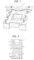
- Fig. 1 is a cutaway view in perspective of the center portion of a substrate of the ink jet recording head of Example 1.
- Fig. 2 is a front view of the entire of the substrate of the ink jet head of Fig. 1.
- Fig. 3 is a graph showing temperature changes with time at the working nozzle row side and at the non-working nozzle row side when ink is discharged from one of the two rows of the nozzles of Fig. 1.
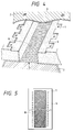
- Fig. 4 is a cutaway view in perspective of the center portion of a substrate of the ink jet recording head of Example 2.
- Fig. 5 is a front view of the entire of the substrate of the ink jet head of Fig. 4.
- Fig. 6 is a graph showing temperature changes with time at the working nozzle row side and at the non-working nozzle row side when ink is discharged from one of the two rows of the nozzles of Fig. 4.
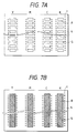
- Figs. 7A and 7B are front views of the color ink jet recording heads of Examples 3 and 4.
- Fig. 8 is a cutaway view in perspective of the center portion of a substrate of the ink jet recording head of prior art.
- Fig. 9 is a front view of the entire of the substrate of the ink jet head of Fig. 8.
- Fig. 10 is a graph showing temperature changes with time at the working nozzle row side and at the non-working nozzle row side when ink is discharged from one of the two rows of the nozzles of Fig. 8.
- Fig. 11 is a perspective view of an ink jet cartridge having a head and an ink tank in integration of the present invention.
- Fig. 12 is a partially cutaway view in perspective of the main portion of an ink jet apparatus equipped with an ink jet cartridge.
- Fig. 13 is a block diagram for an ink jet apparatus.
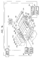
- Fig. 14 is a perspective view of the main portion of an ink jet recording system.
- portions of the substrate for the rows of converting elements are connected by a member having a thermal conductivity coefficient nearly equal to or higher than the thermal conductivity coefficient of the substrate.
- the material constituting the connecting member has a thermal conductivity coefficient nearly equal to the thermal conductivity coefficient of silicon (168 W ⁇ m -1 ⁇ K -1 at 0°C, 800 W ⁇ m -1 ⁇ K -1 at ordinary temperature) used generally as the substrate, preferably not less than 800 W ⁇ m -1 ⁇ K -1 , more preferably 1000 W ⁇ m -1 ⁇ K -1 at ordinary temperature.
- the electrothermal converting elements arranged in rows are separated by an ink supply opening, and are connected at one or more positions by a material having the aforementioned high thermal conductivity.
- the element rows may be connected in any type, and may be connected with one or more bridging members 6 between the element rows as in the ink jet recording head substrate shown in Fig. 1 employed later in Example 1.
- the element rows may be connected with a metallic filter 8 for the recording liquid as shown in Fig. 4 employed later in Example 2.
- a metallic filter for the recording liquid is preferably attached directly to the substrate carrying the electrothermal converting elements thereon to achieve the object of the present invention surely.
- the metallic material therefor includes those having both the aforementioned thermal conductivity coefficient and resistance to corrosion by ink or other substances, specifically including gold, and iridium-tungsten alloys.
- Fig. 11 is a perspective view of an ink jet cartridge of the present invention which has an ink jet head and an ink tank 102 provided with an ink chamber 103 for storing the ink to be supplied to the head in integration.
- the head and the ink tank may be integrated detachably or undetachably.
- a terminal 4a is provided at the end portion of the substrate 4 to supply electric energy to the electrothermal converting elements, and is connected electrically to a terminal on the apparatus side.
- Fig. 12 is a partially cutaway view in perspective of a liquid-discharging apparatus.
- the reference numeral 200 indicates a carriage for setting the aforementioned liquid discharge head in a demountable manner.
- the respective heads are mounted with a yellow ink tank 201Y, a magenta ink tank 201M, a cyan ink tank 201C, and a black ink tank 201B on the carriage 200.
- the carriage 200 is supported by a guide shaft 202, and is moved in two directions on the guide shaft as shown by the arrow mark A by an endless belt 204 driven by a motor 203 rotating reversibly.
- the endless belt 204 is held by pulleys 205 and 206.
- a recording paper sheet P as a medium to be recorded (recording medium) is delivered intermittently in the direction shown by the arrow mark B perpendicular to the arrow mark A.
- the recording paper sheet P is held by a pair of roller units 207, 208 at the sheet-feeding side and another pair of roller units 209, 210 at the sheet-releasing side under a certain tension, and is delivered in a plane state relative to the head.
- the respective roller units are driven by a driving mechanism 211, but may be driven by the aforementioned driving motor.
- the carriage 200 stops at a home position when necessary at the start or during recording.
- a capping member 212 is provided to cap a face of the discharge opening of the head, to which a recovery suction pump (not shown in the drawing) is connected to suck forcibly the discharge opening to prevent clogging of the discharge opening.
- Fig. 13 is a block diagram for operation of an entire liquid-discharging apparatus employing a liquid-discharging head of the present invention.
- the recording apparatus receives printing information as control signal from a host computer 300.
- the printing information is stored temporarily in an input-input interface 301 in the printing apparatus, and is converted to data for processing in the recording apparatus.
- the converted data are inputted to CPU 302 serving also as a means for supplying head drive signals.
- the CPU 302 processes the inputted data according to the control program stored in ROM 303 by employing peripheral units of RAM 304 and the like to convert the inputted data into printing data (image data).
- the CPU 302 also prepares driving data for driving the motor for moving the recording paper sheet and the recording head synchronously with the image data in order to record the image data on a suitable position on the recording paper sheet.
- the image data and the motor-driving data are transmitted through a head driver 307 and a motor driver 305 to the head 200 and the driving motor 306, thereby an image being formed in controlled timing.
- the recording medium which is applicable to the above recording apparatus and is suitable for recording with a recording liquid such as an ink includes paper sheets, OHP sheets, plastic materials used for compact disks and ornament plates, cloths, metals such as aluminum and copper, leathers such as bovine hides, pig hides and artificial leathers, wood materials including wood and plywood, bamboo materials, ceramics such as tiles, and three-dimensional structures such as sponges.
- the recording apparatus includes printer apparatuses for various paper sheets, OHP sheet or the like, plastic-recording apparatuses for plastic recording mediums such as compact disks, metal-recording apparatuses for metal plates, leather-recording apparatuses for leather mediums, wood-recording apparatuses for wood mediums, ceramic-recording apparatuses for ceramic mediums, recording apparatuses for sponges and other three-dimensional network structures, and dye-printing apparatuses for cloths.
- plastic-recording apparatuses for plastic recording mediums such as compact disks
- metal-recording apparatuses for metal plates leather-recording apparatuses for leather mediums
- wood-recording apparatuses for wood mediums wood-recording apparatuses for wood mediums
- ceramic-recording apparatuses for ceramic mediums recording apparatuses for sponges and other three-dimensional network structures
- dye-printing apparatuses for cloths include printer apparatuses for various paper sheets, OHP sheet or the like, plastic-recording apparatuses for
- the discharging liquid for the liquid-discharging apparatus is selected for the respective recording mediums and recording conditions.
- Fig. 14 is a schematic perspective view for explaining an ink jet recording system employing the liquid-discharge head of the present invention.
- the liquid-discharge head in this embodiment is a full-line type head having plural discharge openings at 360 dpi spacing corresponding to the entire recording breadth of the recording medium, and comprises four heads held by a holder 202 for four colors of yellow (Y), magenta (M), cyan (C), and black (Bk).
- the four heads are held by a holder 202 to be fixed in a predetermined intervals in parallel in X direction.
- Signals are applied to the respective heads from a head driver 307 constituting a driving signal-supplying means.
- the respective heads are driven according to the signals.
- inks of four colors of Y, M, C, or Bk are fed from ink containers 204a-204d.
- a blowing liquid container 204e a blowing liquid is fed to the respective heads.
- head caps 203a-203d which have an ink-absorbing material like a sponge therein, and caps the discharge openings of the respective heads to maintain the heads while the recording is not conducted.
- a delivery belt 206 constitutes the delivery means for delivering a recording medium as explained in the aforementioned embodiment.
- the delivery belt 206 is held by rollers through a predetermined path, and is driven by a driving roller connected to a motor driver 305.
- a pre-treatment device 251 and a post-treatment device 252 are provided in the recording medium delivery path for treating the recording medium before and after the recording.
- the pre-treatment and the post-treatment are selected depending on the kind of the employed recording medium and the kind of the employed ink.
- a recording medium such as metal, plastic, or ceramic may be exposed to ultraviolet ray irradiation and ozone atmosphere as the pre-treatment to activate the surface to improve adhesiveness of ink.
- a readily electrifiable recording medium such as plastics is liable to attract dust on the surface to impair the recording quality. Therefore, such a recording medium may be treated by an ionizer device to eliminate static electricity from the recording medium for removal of dusts as the pre-treatment.
- the cloth as the recording medium may be pre-treated by application of an alkaline substance, a water-soluble substance, a synthetic polymer, a water-soluble metal salt, urea, or thiourea for the purpose of prevention of ink running and improvement of fixing ratio.
- the pre-treatment is not limited thereto, and may be temperature adjustment to make the temperature of the recording medium suitable for the recording.
- the post-treatment includes ink-fixation acceleration treatment of ink-applied recording medium, such as heat treatment, and ultraviolet ray irradiation, and washing treatment, to remove an unreacted remaining treating agent having been used in the pre-treatment.
- a full-line head is explained as the head.
- the invention is not limited thereto, and may be a recording apparatus which has a small head moving in a breadth direction of a recording medium as mentioned before.
- Fig. 1 is an enlarged cutaway view in perspective of the center portion of a substrate of an ink jet recording head of the present invention.
- This head was of a side shooter type, and discharge openings were provided on a plane opposing parallel to the plane of the pressure source.
- Electrothermal converting elements or piezo elements were provided on the substrate.
- Ink supply openings were provided through the substrate to communicate with an ink tank placed on the back surface of the substrate.
- the electrothermal converting elements or the piezo elements were arranged on the substrate with interposing the ink supply openings.
- the material for the substrate-connecting portions was silicon, the same material as the substrate provided with the electrothermal converting elements.
- the breadth of the connecting portion was 60 ⁇ m, and the interval between the connecting portions was 100 ⁇ m. Since a broader breadth of the connecting portions retarded the supply of the recording liquid, the breadth was preferably approximate to the above dimensional order.
- the reference numeral 1 indicates an electrothermal converting element; 2, a discharge opening; 3, a nozzle orifice plate; 4, a silicon substrate; 5, a supply opening; 6, a connecting portion characteristic of the present invention connecting the substrate portions 4 interposing the supply opening 5.
- An ink (recording liquid) fills the space between the nozzle orifice plate 3 and the silicon substrate 4. The ink is supplied from the back side of the silicon substrate.
- Fig. 2 shows the surface of the entire substrate viewed from the surface side.
- Fig. 3 is a graph showing temperature changes at a working element opening row side (shown by a solid line) and at a non-working element row side (shown by a dotted line) when ink is discharged continuously from only one of the two rows of the discharging openings.
- Fig. 10 is a graph showing the temperature changes with a conventional head as shown in Figs. 8 and 9. Both of the above two ink jet recording heads employed 256 nozzles at 360 dpi spacing, and apparatus temperature sensors and head temperature sensors to control the head temperature. The driving frequency of the recording head was 10.0 kHz.
- the ink jet recording head of the present invention was excellent in thermal characteristics, and the temperature at the non-working discharge opening side was close to the temperature at the working discharge opening side. Thus the head readily made uniform in temperature distribution.
- solid printing was conducted with one of the two rows of nozzles, and immediately thereafter solid printing was further conducted by use of the other one row of nozzles.
- the optical density of the solid print came to be changed on the switchover of the printing nozzle row from 1.45 to 1.37 with the conventional head, and from 1.45 to 1.43 with the head of this Example. Thus the change was decreased with the head of the present invention.
- Fig. 4 is an enlarged cutaway view in perspective of the center portion of a substrate of another ink jet recording head of the present invention.
- This head was of a side shooter type, and discharge openings were provided on a plane opposing parallel to the plane of the pressure source.
- Electrothermal converting elements or piezo elements were provided on the substrate.
- Ink supplying openings were provided through the substrate to communicate with an ink tank at the back side.
- the electrothermal converting elements or the piezo elements were arranged on the substrate with interposing the ink supplying openings.
- the member for connecting the substrate portions was a metallic filter for filtering the recording liquid.
- the filter was made from gold, and the mesh width of the filter was 12 ⁇ m.
- the reference numeral 1 indicates an electrothermal converting element; 2, a discharge opening; 3, a nozzle orifice plate; 4, a silicon substrate; 5, a supply opening; 7, an ink tank; 8, a metallic filter characteristic of the present invention connecting the substrate portions interposing the supply opening.
- An ink (recording liquid) fills the space between the nozzle orifice plate 3 and the silicon substrate 4. The ink is supplied from the back side of the silicon substrate.
- Fig. 5 shows the surface of the entire substrate viewed from the surface side.
- Fig. 6 is a graph showing temperature changes at a working element row side (shown by a solid line) and at a non-working element row side (shown by a dotted line) when ink is discharged continuously from only one of the two rows of discharging openings.
- the above ink jet recording head employed 256 nozzles in 360 dpi spacing, and apparatus temperature sensors and head temperature sensors to control the head temperature.
- the driving frequency of the recording head was 10.0 kHz.
- the ink jet recording head of the present invention was excellent in thermal characteristics, and the temperature at the non-working discharge opening side was close to the temperature at the working discharge opening side. Thus the head readily was made uniform in temperature distribution.
- the same effects as in Example 1 were achieved. Further, the metallic filter of this Example served also to remove dust from the recording liquid.
- the recording heads had two rows of electrothermal converting elements.
- the present invention is applicable to the recording heads having three or more rows of electrothermal transducers.
- color ink jet recording heads of Y (yellow), M (magenta), C (cyan), and K (black) were employed which respectively have electrothermal converting elements on one and the same substrate, and the ink supply openings communicated with respective color ink tanks as shown in Fig. 7A and Fig. 7B.
- connecting members were provided at the ink supply openings for respective color inks.
- metallic filters 8 were provided at the ink supply openings.
- heat could be diffused also through the portion of the substrate between the ink supply openings 5 to uniformize the temperature distribution.
- an ink jet recording head which has satisfactory ink discharging characteristics throughout all the electrothermal converting elements with uniform temperature distribution, and gives output without printing density uneveness. Further, by use of a metallic filter as the connecting member according to the present invention, an ink jet recording head is provided which requires no additional filter and has excellent temperature characteristics.
- An ink jet head comprises ink discharge openings for discharging ink and a substrate having a plurality of rows in each of which a plurality of electrothermal converting elements for generating thermal energy for discharging ink from the discharge openings are provided and having an ink supply opening between the rows of the plurality of electrothermal converting elements corresponding to length of the row, wherein portions of the substrate having the row disposed the plurality of electrothermal converting elements are connected to each other by a member having a thermal conductivity coefficient nearly equal to or higher than that of the substrate.
Landscapes
- Physics & Mathematics (AREA)
- Thermal Sciences (AREA)
- Particle Formation And Scattering Control In Inkjet Printers (AREA)
- Ink Jet (AREA)
Applications Claiming Priority (3)
| Application Number | Priority Date | Filing Date | Title |
|---|---|---|---|
| JP221813/95 | 1995-08-30 | ||
| JP22181395 | 1995-08-30 | ||
| JP22181395 | 1995-08-30 |
Publications (3)
| Publication Number | Publication Date |
|---|---|
| EP0760287A2 true EP0760287A2 (fr) | 1997-03-05 |
| EP0760287A3 EP0760287A3 (fr) | 1997-07-30 |
| EP0760287B1 EP0760287B1 (fr) | 2002-06-12 |
Family
ID=16772603
Family Applications (1)
| Application Number | Title | Priority Date | Filing Date |
|---|---|---|---|
| EP96113819A Expired - Lifetime EP0760287B1 (fr) | 1995-08-30 | 1996-08-29 | Tête à jet d'encre, cartouche à jet d'encre, et dispositif à jet d'encre |
Country Status (3)
| Country | Link |
|---|---|
| US (1) | US6557983B1 (fr) |
| EP (1) | EP0760287B1 (fr) |
| DE (1) | DE69621717T2 (fr) |
Cited By (3)
| Publication number | Priority date | Publication date | Assignee | Title |
|---|---|---|---|---|
| EP1925449A3 (fr) * | 2006-11-23 | 2009-05-06 | Samsung Electronics Co., Ltd. | Puce de tête et cartouche d'encre et appareil de formation d'image doté de celles-ci |
| EP2209635A4 (fr) * | 2007-10-15 | 2011-03-02 | Hewlett Packard Development Co | Nervures de fente de filière de tête d'impression |
| EP2276633A4 (fr) * | 2008-05-06 | 2011-08-24 | Hewlett Packard Development Co | Nervures de fente d'alimentation de tête d'impression |
Families Citing this family (22)
| Publication number | Priority date | Publication date | Assignee | Title |
|---|---|---|---|---|
| US6746106B1 (en) * | 2003-01-30 | 2004-06-08 | Hewlett-Packard Development Company, L.P. | Fluid ejection device |
| WO2007041744A1 (fr) * | 2005-10-10 | 2007-04-19 | Silverbrook Research Pty Ltd | Connexion d'electrodes a faible perte pour tete d'impression a jet d'encre |
| US7744195B2 (en) * | 2005-10-11 | 2010-06-29 | Silverbrook Research Pty Ltd | Low loss electrode connection for inkjet printhead |
| US7465041B2 (en) * | 2005-10-11 | 2008-12-16 | Silverbrook Research Pty Ltd | Inkjet printhead with inlet priming feature |
| US7712869B2 (en) | 2005-10-11 | 2010-05-11 | Silverbrook Research Pty Ltd | Inkjet printhead with controlled drop misdirection |
| US7712876B2 (en) * | 2005-10-11 | 2010-05-11 | Silverbrook Research Pty Ltd | Inkjet printhead with opposing actuator electrode polarities |
| US7712884B2 (en) * | 2005-10-11 | 2010-05-11 | Silverbrook Research Pty Ltd | High density thermal ink jet printhead |
| US7708387B2 (en) * | 2005-10-11 | 2010-05-04 | Silverbrook Research Pty Ltd | Printhead with multiple actuators in each chamber |
| US7735971B2 (en) | 2005-10-11 | 2010-06-15 | Silverbrook Research Pty Ltd | Printhead with elongate nozzles |
| US7401890B2 (en) * | 2005-10-11 | 2008-07-22 | Silverbrook Research Pty Ltd | Intercolour surface barriers in multi colour inkjet printhead |
| US7445317B2 (en) * | 2005-10-11 | 2008-11-04 | Silverbrook Research Pty Ltd | Inkjet printhead with droplet stem anchor |
| US7322681B2 (en) * | 2005-10-11 | 2008-01-29 | Silverbrook Research Pty Ltd | Printhead with ink feed to chamber via adjacent chamber |
| US7753496B2 (en) | 2005-10-11 | 2010-07-13 | Silverbrook Research Pty Ltd | Inkjet printhead with multiple chambers and multiple nozzles for each drive circuit |
| US7597425B2 (en) * | 2005-10-11 | 2009-10-06 | Silverbrook Research Pty Ltd | Inkjet printhead with multiple heater elements in parallel |
| US7465032B2 (en) * | 2005-10-11 | 2008-12-16 | Silverbrook Research Pty Ltd. | Printhead with inlet filter for ink chamber |
| US7470010B2 (en) * | 2005-10-11 | 2008-12-30 | Silverbrook Research Pty Ltd | Inkjet printhead with multiple ink inlet flow paths |
| US7661800B2 (en) * | 2005-10-11 | 2010-02-16 | Silverbrook Research Pty Ltd | Inkjet printhead with multiple heater elements and cross bracing |
| AT505819B1 (de) * | 2007-09-26 | 2009-07-15 | Elag Ast Gmbh | Verfahren und vorrichtung zum herstellen von mit servietten bestückten taschen |
| JP5288825B2 (ja) * | 2008-02-22 | 2013-09-11 | キヤノン株式会社 | インクジェット記録ヘッド |
| JP5202126B2 (ja) * | 2008-06-17 | 2013-06-05 | キヤノン株式会社 | 記録ヘッド用基板、インクジェット記録ヘッドおよびインクジェット記録装置 |
| JP5679665B2 (ja) * | 2009-02-06 | 2015-03-04 | キヤノン株式会社 | インクジェット記録ヘッド |
| JP5202371B2 (ja) * | 2009-02-06 | 2013-06-05 | キヤノン株式会社 | インクジェット記録ヘッド |
Family Cites Families (10)
| Publication number | Priority date | Publication date | Assignee | Title |
|---|---|---|---|---|
| JPH0753450B2 (ja) | 1984-03-31 | 1995-06-07 | キヤノン株式会社 | 液体噴射記録装置 |
| DE3717294C2 (de) * | 1986-06-10 | 1995-01-26 | Seiko Epson Corp | Tintenstrahlaufzeichnungskopf |
| US5204690A (en) * | 1991-07-01 | 1993-04-20 | Xerox Corporation | Ink jet printhead having intergral silicon filter |
| US5317346A (en) | 1992-03-04 | 1994-05-31 | Hewlett-Packard Company | Compound ink feed slot |
| US5537133A (en) | 1992-04-02 | 1996-07-16 | Hewlett-Packard Company | Restraining element for a print cartridge body to reduce thermally induced stress |
| US5424767A (en) | 1993-03-02 | 1995-06-13 | Tektronix, Inc. | Apparatus and method for heating ink to a uniform temperature in a multiple-orifice phase-change ink-jet print head |
| US5666140A (en) | 1993-04-16 | 1997-09-09 | Hitachi Koki Co., Ltd. | Ink jet print head |
| US5896154A (en) | 1993-04-16 | 1999-04-20 | Hitachi Koki Co., Ltd. | Ink jet printer |
| US5463413A (en) | 1993-06-03 | 1995-10-31 | Hewlett-Packard Company | Internal support for top-shooter thermal ink-jet printhead |
| US5322594A (en) * | 1993-07-20 | 1994-06-21 | Xerox Corporation | Manufacture of a one piece full width ink jet printing bar |
-
1996
- 1996-08-28 US US08/704,104 patent/US6557983B1/en not_active Expired - Lifetime
- 1996-08-29 EP EP96113819A patent/EP0760287B1/fr not_active Expired - Lifetime
- 1996-08-29 DE DE69621717T patent/DE69621717T2/de not_active Expired - Lifetime
Cited By (4)
| Publication number | Priority date | Publication date | Assignee | Title |
|---|---|---|---|---|
| EP1925449A3 (fr) * | 2006-11-23 | 2009-05-06 | Samsung Electronics Co., Ltd. | Puce de tête et cartouche d'encre et appareil de formation d'image doté de celles-ci |
| EP2209635A4 (fr) * | 2007-10-15 | 2011-03-02 | Hewlett Packard Development Co | Nervures de fente de filière de tête d'impression |
| EP2276633A4 (fr) * | 2008-05-06 | 2011-08-24 | Hewlett Packard Development Co | Nervures de fente d'alimentation de tête d'impression |
| US8733902B2 (en) | 2008-05-06 | 2014-05-27 | Hewlett-Packard Development Company, L.P. | Printhead feed slot ribs |
Also Published As
| Publication number | Publication date |
|---|---|
| DE69621717D1 (de) | 2002-07-18 |
| DE69621717T2 (de) | 2002-11-21 |
| EP0760287B1 (fr) | 2002-06-12 |
| US6557983B1 (en) | 2003-05-06 |
| EP0760287A3 (fr) | 1997-07-30 |
Similar Documents
| Publication | Publication Date | Title |
|---|---|---|
| EP0760287B1 (fr) | Tête à jet d'encre, cartouche à jet d'encre, et dispositif à jet d'encre | |
| EP1205307B1 (fr) | Appareil d'impression à jet d'encre et procédé d'éjection préliminaire | |
| US5721574A (en) | Ink detecting mechanism for a liquid ink printer | |
| JPH03234539A (ja) | インクジェット記録装置 | |
| US6352333B2 (en) | Method and apparatus for preventing nozzle clogging in ink jet printing apparatus | |
| US6447096B1 (en) | Ink jet recording apparatus and recovery method therefor | |
| JP2001105628A (ja) | 画像形成装置 | |
| EP1510342B1 (fr) | Tête jet d'encre et appareil d'enregistrement à jet d'encre | |
| JP3743568B2 (ja) | インクジェット記録装置 | |
| JPH03213350A (ja) | インクジェット記録装置 | |
| JPH07101081A (ja) | インクジェット記録装置 | |
| JP3563883B2 (ja) | インクジェットヘッド及びインクジェットヘッド用基板 | |
| US20020036672A1 (en) | Ink jet printer having a printhead and a method of removing air bubbles | |
| US7273267B2 (en) | Bubble-eliminating liquid filling method, droplet discharging apparatus, and inkjet recording apparatus | |
| JP2001179953A (ja) | インクジェット記録装置 | |
| US6817694B1 (en) | Ink jet system image forming device | |
| JPS62116152A (ja) | 記録装置 | |
| JPH0480041A (ja) | インクジェット記録方法およびその装置 | |
| JPH1199666A (ja) | インクジェット記録装置 | |
| JPH06134997A (ja) | インクジェット記録装置 | |
| JP3639698B2 (ja) | 液体吐出ヘッド、ヘッドカートリッジ、液体吐出記録装置、および液体吐出ヘッドの製造方法 | |
| JP3363605B2 (ja) | インクジェット記録装置 | |
| JP3248544B2 (ja) | インクジェット記録装置 | |
| JPH054335A (ja) | 記録装置 | |
| JPH0516476A (ja) | ロール紙カートリツジおよび該ロール紙カートリツジを備えた記録装置 |
Legal Events
| Date | Code | Title | Description |
|---|---|---|---|
| PUAI | Public reference made under article 153(3) epc to a published international application that has entered the european phase |
Free format text: ORIGINAL CODE: 0009012 |
|
| AK | Designated contracting states |
Kind code of ref document: A2 Designated state(s): DE FR GB IT |
|
| PUAL | Search report despatched |
Free format text: ORIGINAL CODE: 0009013 |
|
| AK | Designated contracting states |
Kind code of ref document: A3 Designated state(s): DE FR GB IT |
|
| 17P | Request for examination filed |
Effective date: 19971216 |
|
| 17Q | First examination report despatched |
Effective date: 19990712 |
|
| GRAG | Despatch of communication of intention to grant |
Free format text: ORIGINAL CODE: EPIDOS AGRA |
|
| RTI1 | Title (correction) |
Free format text: INK JET HEAD, INK JET CARTRIDGE, AND INK JET APPARATUS |
|
| GRAG | Despatch of communication of intention to grant |
Free format text: ORIGINAL CODE: EPIDOS AGRA |
|
| GRAH | Despatch of communication of intention to grant a patent |
Free format text: ORIGINAL CODE: EPIDOS IGRA |
|
| GRAH | Despatch of communication of intention to grant a patent |
Free format text: ORIGINAL CODE: EPIDOS IGRA |
|
| GRAA | (expected) grant |
Free format text: ORIGINAL CODE: 0009210 |
|
| AK | Designated contracting states |
Kind code of ref document: B1 Designated state(s): DE FR GB IT |
|
| REG | Reference to a national code |
Ref country code: GB Ref legal event code: FG4D |
|
| REF | Corresponds to: |
Ref document number: 69621717 Country of ref document: DE Date of ref document: 20020718 |
|
| ET | Fr: translation filed | ||
| PLBE | No opposition filed within time limit |
Free format text: ORIGINAL CODE: 0009261 |
|
| STAA | Information on the status of an ep patent application or granted ep patent |
Free format text: STATUS: NO OPPOSITION FILED WITHIN TIME LIMIT |
|
| 26N | No opposition filed |
Effective date: 20030313 |
|
| PGFP | Annual fee paid to national office [announced via postgrant information from national office to epo] |
Ref country code: DE Payment date: 20140831 Year of fee payment: 19 |
|
| PGFP | Annual fee paid to national office [announced via postgrant information from national office to epo] |
Ref country code: FR Payment date: 20140827 Year of fee payment: 19 Ref country code: GB Payment date: 20140822 Year of fee payment: 19 |
|
| PGFP | Annual fee paid to national office [announced via postgrant information from national office to epo] |
Ref country code: IT Payment date: 20140715 Year of fee payment: 19 |
|
| REG | Reference to a national code |
Ref country code: DE Ref legal event code: R119 Ref document number: 69621717 Country of ref document: DE |
|
| GBPC | Gb: european patent ceased through non-payment of renewal fee |
Effective date: 20150829 |
|
| PG25 | Lapsed in a contracting state [announced via postgrant information from national office to epo] |
Ref country code: IT Free format text: LAPSE BECAUSE OF NON-PAYMENT OF DUE FEES Effective date: 20150829 |
|
| REG | Reference to a national code |
Ref country code: FR Ref legal event code: ST Effective date: 20160429 |
|
| PG25 | Lapsed in a contracting state [announced via postgrant information from national office to epo] |
Ref country code: GB Free format text: LAPSE BECAUSE OF NON-PAYMENT OF DUE FEES Effective date: 20150829 Ref country code: DE Free format text: LAPSE BECAUSE OF NON-PAYMENT OF DUE FEES Effective date: 20160301 |
|
| PG25 | Lapsed in a contracting state [announced via postgrant information from national office to epo] |
Ref country code: FR Free format text: LAPSE BECAUSE OF NON-PAYMENT OF DUE FEES Effective date: 20150831 |