EP0760305A2 - Einzelradantrieb für ein elektrisch angetriebenes Fahrzeug - Google Patents
Einzelradantrieb für ein elektrisch angetriebenes Fahrzeug Download PDFInfo
- Publication number
- EP0760305A2 EP0760305A2 EP96113704A EP96113704A EP0760305A2 EP 0760305 A2 EP0760305 A2 EP 0760305A2 EP 96113704 A EP96113704 A EP 96113704A EP 96113704 A EP96113704 A EP 96113704A EP 0760305 A2 EP0760305 A2 EP 0760305A2
- Authority
- EP
- European Patent Office
- Prior art keywords
- motor
- drive
- wheel
- drive unit
- independent wheel
- Prior art date
- Legal status (The legal status is an assumption and is not a legal conclusion. Google has not performed a legal analysis and makes no representation as to the accuracy of the status listed.)
- Granted
Links
Images


Classifications
-
- H—ELECTRICITY
- H02—GENERATION; CONVERSION OR DISTRIBUTION OF ELECTRIC POWER
- H02K—DYNAMO-ELECTRIC MACHINES
- H02K5/00—Casings; Enclosures; Supports
- H02K5/04—Casings or enclosures characterised by the shape, form or construction thereof
-
- B—PERFORMING OPERATIONS; TRANSPORTING
- B61—RAILWAYS
- B61C—LOCOMOTIVES; MOTOR RAILCARS
- B61C9/00—Locomotives or motor railcars characterised by the type of transmission system used; Transmission systems specially adapted for locomotives or motor railcars
- B61C9/38—Transmission systems in or for locomotives or motor railcars with electric motor propulsion
- B61C9/46—Transmission systems in or for locomotives or motor railcars with electric motor propulsion with motors forming parts of wheels
-
- H—ELECTRICITY
- H02—GENERATION; CONVERSION OR DISTRIBUTION OF ELECTRIC POWER
- H02K—DYNAMO-ELECTRIC MACHINES
- H02K7/00—Arrangements for handling mechanical energy structurally associated with dynamo-electric machines, e.g. structural association with mechanical driving motors or auxiliary dynamo-electric machines
- H02K7/10—Structural association with clutches, brakes, gears, pulleys or mechanical starters
- H02K7/116—Structural association with clutches, brakes, gears, pulleys or mechanical starters with gears
-
- H—ELECTRICITY
- H02—GENERATION; CONVERSION OR DISTRIBUTION OF ELECTRIC POWER
- H02K—DYNAMO-ELECTRIC MACHINES
- H02K7/00—Arrangements for handling mechanical energy structurally associated with dynamo-electric machines, e.g. structural association with mechanical driving motors or auxiliary dynamo-electric machines
- H02K7/08—Structural association with bearings
Definitions
- the invention relates to an independent wheel drive for an electrically driven vehicle, the drive unit being arranged in a cushioned manner on the chassis.
- German patent application P 44 45 407.4 is an independent wheel drive, in which a motor is attached with its stator to a first chassis part and in which the first chassis part is supported by a primary suspension on an unsprung second chassis part, on which the single wheel is rotatably supported, wherein the rotor of the motor transmits its torque via a coupling device, the radial mobility of which is greater than the spring travel of the primary suspension.
- a single wheel drive which is particularly suitable for electrically powered rail vehicles, the proportion of unsprung masses is low.
- this wheel hub drive which is sprung against two chassis parts, a special driving wheel construction is provided for the arrangement of the motor.
- the motor structure requires a relatively large axial length of the entire drive unit with a separate brake disc and requires large bearings.
- a drive with a vertical electric motor and with a bevel gear to the drive wheel axis is provided.
- the disadvantage here is the high weight of such a drive unit and the lower efficiency in the power transmission due to the bevel gear.
- a special configuration of the vehicle clearance profile is required.
- the object of the invention is to provide a fully sprung independent wheel drive, which is characterized by small dimensions and high efficiency in power transmission.
- this object is achieved in a single-wheel drive of the type mentioned at the outset in that the rotor of the motor, which is seated on a hollow shaft, drives a drive shaft guided through the hollow shaft via a planetary gear, and that an elastic coupling is assigned to the end of the drive shaft facing the drive wheel of the vehicle wherein the elastic coupling transmits the torque of the engine to the drive wheel, and that the drive unit is kept cushioned against a chassis part.
- Such a single wheel drive which is particularly suitable for driving rail vehicles, such as low-floor trams, or buses, forms a fully sprung drive which is arranged between the driving wheel of the vehicle and the lateral vehicle outer limit, the drive being arranged upstream of a conventionally simply designed and mounted driving wheel.
- the drive is characterized in particular by its small axial length and its relatively low weight and can be easily accommodated in the clearance profile of the vehicle.
- the drive unit according to the invention only needs to be kept cushioned against a chassis part.
- the axial overall length of the drive unit according to the invention consisting of clutch, motor and transmission is smaller than the outer diameter of the drive unit determined by the motor.
- the ratio of the axial overall length of the motor laminated core to the outer diameter of the motor is in a range from 0.15 to 0.3.
- the ratio of the axial length of the motor laminated core to the outer diameter of the motor is between 0.16 and 0.25.
- An advantageous embodiment of the drive unit with respect to the motor and transmission housing is achieved in that an engine end shield facing away from the drive wheel forms the transmission housing with an outer end cover.
- the motor end shield is profiled in such a way that it is drawn into the engine compartment below the stator winding, in such a way that the ring gear of the planetary gear can be arranged at least partially below the stator winding.
- a further reduction in the axial overall length is achieved if a motor bearing plate assigned to the driving wheel is profiled such that it is drawn into the engine compartment below the stator winding and that the elastic coupling can be arranged below the stator winding between the motor bearing plate and the driving wheel.
- Another size-reducing design of the single wheel drive is achieved in that at least part of a braking device with an associated brake disc is arranged between the driving wheel and the drive unit.
- a drive wheel 7 is mounted via a stub axle 23 and a wheel axle bearing 24 in a known arrangement.
- the drive unit 1, which drives the driving wheel 7 via an elastic coupling 9, is spring-loaded against the chassis part 10, in the exemplary embodiment a wheel carrier, by means of a suspension 25. Because of this cushioning, the drive unit 1 can oscillate around the bearing point P of the wheel axle 23 by a limited angle a.
- Brake levers 20, 26 and brake disks 21, 27 of an intended brake are drawn on both sides of the driving wheel 7, the arrangement of the braking device 20, 21 between the driving wheel 7 and the drive unit 1 due to the profiled design of the associated motor end shield 16 having a very compact single-wheel drive with a short axial Length allowed.
- the drive unit is characterized by an electric motor 4 of a small axial length.
- the axial overall length of the drive assembly 1 consisting of the clutch 9, the motor 4 and a transmission 5 is smaller than the outer diameter D of the drive assembly determined by the motor 4.
- the ratio of the axial overall length of the motor laminated core 11 to the outer diameter of the motor 4 is between approximately 0.15 and 0.3.
- the rotor 3 of the motor 4 which is seated on a hollow shaft 2, drives a drive shaft 6 guided through the hollow shaft via a planetary gear 5.
- the end 8 of the drive shaft 6, which faces the driving wheel 7 of the vehicle is assigned an elastic coupling 9 known per se, which takes over the power transmission between the drive shaft 6 and the driving wheel 7.
- a bearing 17, 18 of the hollow shaft 2 or of the rotor 3 of the motor 4 is provided according to an advantageous embodiment for the axially short motor in the retracted regions of the motor end shields 12, 16.
- a bearing 19 of the drive shaft 6 is arranged in the retracted area of the motor bearing plate 16 on the driving wheel side.
Landscapes
- Engineering & Computer Science (AREA)
- Power Engineering (AREA)
- Chemical & Material Sciences (AREA)
- Combustion & Propulsion (AREA)
- Transportation (AREA)
- Mechanical Engineering (AREA)
- Arrangement Or Mounting Of Propulsion Units For Vehicles (AREA)
- Automatic Cycles, And Cycles In General (AREA)
- Transmission Devices (AREA)
- Elimination Of Static Electricity (AREA)
- Electric Propulsion And Braking For Vehicles (AREA)
- Hybrid Electric Vehicles (AREA)
- Connection Of Motors, Electrical Generators, Mechanical Devices, And The Like (AREA)
Abstract
Description
- Die Erfindung betrifft einen Einzelradantrieb für ein elektrisch angetriebenes Fahrzeug, wobei das Antriebsaggregat abgefedert am Fahrwerk angeordnet ist.
- Gegenstand der deutschen Patentanmeldung P 44 45 407.4 ist ein Einzelradantrieb, bei dem ein Motor mit seinem Stator an einem ersten Fahrwerksteil befestigt ist und bei dem sich das erste Fahrwerksteil über eine Primärfederung an einem ungefederten zweiten Fahrwerksteil abstützt, auf dem das Einzelrad drehbar gelagert ist, wobei der Rotor des Motors sein Drehmoment über eine Kopplungseinrichtung überträgt, deren radiale Beweglichkeit größer ist als der Federweg der Primärfederung. Bei einem derartigen Einzelradantrieb, der insbesondere für elektrisch angetriebene Schienenfahrzeuge geeignet ist, ist der Anteil an ungefederten Massen gering. Bei diesem gegen zwei Fahrwerksteile abgefederten Radnabenantrieb ist für die Anordnung des Motors eine besondere Treibradkonstruktion vorgesehen. Der Motoraufbau bedingt eine relativ große axiale Baulänge des gesamten Antriebsaggregates mit separater Bremsscheibe und erfordert große Lager.
- Bei Niederflurschienenfahrzeugen, wie sie die Stadtwerke in Wien einsetzen, ist ein Antrieb mit einem senkrecht stehenden Elektromotor und mit einem Kegelradgetriebe zur Treibradachse vorgesehen. Nachteilig dabei ist das hohe Gewicht eines solchen Antriebsaggregates und der durch das Kegelradgetriebe bedingte geringere Wirkungsgrad in der Kraftübertragung. Außerdem ist wegen der seitlichen Anbringung des Motors neben dem Treibrad eine besondere Ausgestaltung des Fahrzeug-Lichtraumprofiles erforderlich.
- Aufgabe der Erfindung ist es, einen voll abgefederten Einzelradantrieb zu schaffen, der sich durch geringe Abmessungen und einen hohen Wirkungsgrad in der Kraftübertragung auszeichnet.
- Erfindungsgemäß wird diese Aufgabe bei einem Einzelradantrieb der eingangs genannten Art dadurch gelöst, daß der auf einer Hohlwelle sitzende Rotor des Motors über ein Planetengetriebe eine durch die Hohlwelle geführte Antriebswelle antreibt, daß dem dem Treibrad des Fahrzeuges zugewandten Ende der Antriebswelle eine elastische Kupplung zugeordnet ist, wobei die elastische Kupplung das Drehmoment des Motors auf das Treibrad überträgt, und daß das Antriebsaggregat gegen ein Fahrwerksteil abgefedert gehalten ist.
- Ein derartiger, insbesondere zum Antrieb von Schienenfahrzeugen, wie Niederflurstraßenbahnen, oder von Bussen geeigneter Einzelradantrieb bildet einen voll abgefederten Antrieb, der zwischen dem Treibrad des Fahrzeuges und der seitlichen Fahrzeugaußenbegrenzung angeordnet wird, wobei der Antrieb einem konventionell einfach ausgebildeten und gelagerten Treibrad vorgeordnet ist. Der Antrieb zeichnet sich dabei insbesondere durch seine geringe axiale Baulänge und sein relativ geringes Gewicht aus und ist im Lichtraumprofil des Fahrzeuges gut unterbringbar. Gegenüber dem Radnabenmotor gemäß Patentanmeldung P 44 45 407.4 braucht das erfindungsgemäße Antriebsaggregat nur gegen ein Fahrwerksteil abgefedert gehalten zu werden.
- In vorteilhafter Ausbildung der Erfindung ist die axiale Baulänge des aus Kupplung, Motor und Getriebe bestehenden erfindungsgemäßen Antriebsaggregates kleiner als der durch den Motor bestimmte Außendurchmesser des Antriebsaggregates. In vorteilhafter Auslegung liegt Verhältnis der axialen Baulänge des Motorblechpaketes zum Außendurchmesser des Motors in einem Bereich von 0,15 bis 0,3. Bei vorteilhaften Ausführungsformen liegt das Verhältnis der axialen Baulänge des Motorblechpaketes zum Außendurchmesser des Motors bei Werten von 0,16 bis 0,25.
- Eine vorteilhafte Ausbildung des Antriebsaggregates bezüglich Motor- und Getriebegehäuse wird dadurch erreicht, daß ein dem Treibrad abgewandtes Motorlagerschild des Antriebsaggregates mit einem äußeren Abschlußdeckel das Getriebegehäuse bildet.
- Zur Reduzierung der axialen Baulänge des Antriebsaggregates gemäß der Erfindung trägt bei, daß das Motorlagerschild derart profiliert ist, daß es unterhalb der Statorwicklung in den Motorraum eingezogen ist, derart, daß das Hohlrad des Planetengetriebes zumindest teilweise unterhalb der Statorwicklung angeordnet werden kann.
- Eine weitere Reduzierung der axialen Baulänge wird dann erreicht, wenn ein dem Treibrad zugeordnetes Motorlagerschild derart profiliert ist, daß es unterhalb der Statorwicklung in den Motorraum eingezogen ist und daß unterhalb der Statorwicklung zwischen dem Motorlagerschild und dem Treibrad die elastische Kupplung angeordnet werden kann.
- Eine weitere, die Baugröße reduzierende Ausbildung des Einzelradantriebes wird dadurch erreicht, daß zwischen dem Treibrad und dem Antriebsaggregat wenigstens ein Teil einer Bremsvorrichtung mit zugehöriger Bremsscheibe angeordnet ist.
- Weitere Vorteile und Einzelheiten der Erfindung ergeben sich aus der nachfolgenden Beschreibung von Ausführungsbeispielen anhand der Zeichnung und in Verbindung mit den in den Patentansprüchen gekennzeichneten Merkmalen.
- Es zeigen:
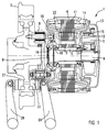
- Figur 1 einen erfindungsgemäßen Einzelradantrieb eines Treibrades eines elektrischen Schienenfahrzeuges im Längsschnitt,
- Figur 2 eine Ansicht eines Einzelradantriebes gemäß Figur 1, jedoch teilweise um 90° gedreht gezeichnet, mit der federnden Aufhängung des Antriebsaggregates gegen ein Fahrwerksteil,
- Figur 3 eine Seitenansicht zu Figur 2.
- An dem in Figur 2 dargestellten Fahrwerksteil 10 eines Schienenfahrzeuges ist in an sich bekannter Anordnung ein Treibrad 7 über einen Achsstummel 23 und ein Radachslager 24 gelagert. Das das Treibrad 7 über eine elastische Kupplung 9 antreibende Antriebsaggregat 1 ist über eine Federung 25 gegen das Fahrwerksteil 10, im Ausführungsbeispiel ein Radträger, abgefedert gehalten. Aufgrund dieser Abfederung kann das Antriebsaggregat 1 um den Lagerpunkt P der Radachse 23 um einen begrenzten Winkel a pendeln. Zu beiden Seiten des Treibrades 7 sind Bremshebel 20, 26 und Bremsscheiben 21, 27 einer vorgesehenen Bremse gezeichnet, wobei die Anordnung der Bremsvorrichtung 20, 21 zwischen Treibrad 7 und Antriebsaggregat 1 aufgrund der profilierten Ausbildung des zugeordneten Motorlagerschildes 16 einen sehr kompakten Einzelradantrieb mit kurzer axialer Baulänge ermöglicht.
- Das Antriebsaggregat zeichnet sich durch einen Elektromotor 4 von einer geringen axialen Baulänge aus. Dabei ist die axiale Baulänge des aus der Kupplung 9, dem Motor 4 und einem Getriebe 5 bestehenden Antriebsaggregates 1 kleiner als der durch den Motor 4 bestimmte Außendurchmesser D des Antriebsaggregates. In einer vorteilhaften Ausbildung liegt das Verhältnis der axialen Baulänge des Motorblechpaketes 11 zum Außendurchmesser des Motors 4 bei Werten zwischen etwa 0,15 und 0,3.
- Der auf einer Hohlwelle 2 sitzende Rotor 3 des Motors 4 treibt über ein Planetengetriebe 5 eine durch die Hohlwelle geführte Antriebswelle 6 an. Dem Ende 8 der Antriebswelle 6, welches dem Treibrad 7 des Fahrzeuges zugewandt ist, ist eine an sich bekannte, elastische Kupplung 9 zugeordnet, welche die Kraftübertragung zwischen der Antriebswelle 6 und dem Treibrad 7 übernimmt. Eine Lagerung 17, 18 der Hohlwelle 2 bzw. des Rotors 3 des Motors 4 ist nach vorteilhafter Ausführung für den axial kurz gebauten Motor in den eingezogen ausgebildeten Bereichen der Motorlagerschilde 12, 16 vorgesehen. Des weiteren ist eine Lagerung 19 der Antriebswelle 6 im eingezogenen Bereich des treibradseitigen Motorlagerschildes 16 angeordnet.
- Bei Schienenfahrzeugen, wie Eisenbahnfahrzeugen und Straßenbahnen, oder bei Bussen, ist bei der Anordnung und Ausgestaltung der Antriebe darauf zu achten, daß das Antriebsaggregat nicht über das Seitenprofil des Fahrzeuges hinausragt. Um das sogenannte Lichtraumprofil des Fahrzeuges einzuhalten, ist vorgesehen, daß der äußere Abschlußdeckel 13 des Antriebsaggregates 1 innerhalb des Fahrzeugprofiles liegt oder mit diesem deckungsgleich ist.
- Zwischen der mit dem Motorgehäuse feststehenden Statorwicklung 14 und dem drehenden Rotor 3 befindet sich ein Luftspalt 22, wobei zur platzsparenden kurzen Motorbauweise das Hohlrad 15 des Planetengetriebes 5 so angeordnet wird, daß es sich zumindest teilweise unterhalb der Statorwicklung 14 befindet.
Claims (10)
- Einzelradantrieb für ein elektrisch angetriebenes Fahrzeug, wobei das Antriebsaggregat (1) abgefedert am Fahrwerk angeordnet ist, dadurch gekennzeichnet, daß der auf einer Hohlwelle (2) sitzende Rotor (3) des Motors (4) über ein Planetengetriebe (5) eine durch die Hohlwelle geführte Antriebswelle (6) antreibt, daß dem dem Treibrad (7) des Fahrzeuges zugewandten Ende (8) der Antriebswelle (6) eine elastische Kupplung (9) zugeordnet ist, wobei die elastische Kupplung das Drehmoment des Motors auf das Treibrad überträgt, und daß das Antriebsaggregat (1) gegen ein Fahrwerksteil (10) abgefedert gehalten ist.
- Einzelradantrieb nach Anspruch 1, dadurch gekennzeichnet, daß die axiale Baulänge des aus Kupplung (9), Motor (4) und Getriebe (5) bestehenden Antriebsaggregates (1) kleiner als der durch den Motor (4) bestimmte Außendurchmesser des Antriebsaggregates (1) ist.
- Einzelradantrieb nach Anspruch 2, dadurch gekennzeichnet, daß die axiale Baulänge des Motorblechpaketes (11) zum Außendurchmesser des Motors (4) in einem Verhältnis von 0,15 bis 0,3 ausgelegt ist.
- Einzelradantrieb nach einem der Ansprüche 1 bis 3, dadurch gekennzeichnet, daß ein dem Treibrad (7) abgewandtes Motorlagerschild (12) mit einem äußeren Abschlußdeckel (13) das Getriebegehäuse bildet.
- Einzelradantrieb nach Anspruch 4, dadurch gekennzeichnet, daß der Abschlußdeckel (13) des Antriebsaggregates (1) innerhalb des Fahrzeugprofiles liegt oder mit diesem deckungsgleich ist.
- Einzelradantrieb nach einem der Ansprüche 1 bis 5, dadurch gekennzeichnet, daß das Motorlagerschild (12) derart profiliert ist, daß es unterhalb der Statorwicklung (14) in den Motorraum eingezogen ist und daß das Hohlrad (15) des Planetengetriebes (5) zumindest teilweise unterhalb der Statorwicklung (14) angeordnet ist.
- Einzelradantrieb nach einem der Ansprüche 1 bis 6, dadurch gekennzeichnet, daß ein dem Treibrad (7) zugeordnetes Motorlagerschild (16) derart profiliert ist, daß es unterhalb der Statorwicklung (14) in den Motorraum eingezogen ist und daß unterhalb der Statorwicklung (14) zwischen dem Motorlagerschild (16) und dem Treibrad (7) die elastische Kupplung (9) angeordnet ist.
- Einzelradantrieb nach einem der Ansprüche 1 bis 7, dadurch gekennzeichnet, daß eine Lagerung (17, 18) der Hohlwelle (2) mit aufgesetztem Rotor (3) im eingezogenen Bereich der Motorlagerschilde (12, 16) vorgesehen ist.
- Einzelradantrieb nach einem der Ansprüche 1 bis 8, dadurch gekennzeichnet, daß eine Lagerung (19) der Antriebswelle (6) im eingezogenen Bereich des treibradseitigen Motorlagerschildes (16) vorgesehen ist.
- Einzelradantrieb nach einem der Ansprüche 1 bis 9, dadurch gekennzeichnet, daß zwischen dem Treibrad (7) und dem Antriebsaggregat (1) wenigstens ein Teil einer Bremsvorrichtung (20) mit zugehöriger Bremsscheibe (21) angeordnet ist.
Applications Claiming Priority (2)
| Application Number | Priority Date | Filing Date | Title |
|---|---|---|---|
| DE19531956 | 1995-08-30 | ||
| DE19531956A DE19531956A1 (de) | 1995-08-30 | 1995-08-30 | Einzelradantrieb für ein elektrisch angetriebenes Fahrzeug |
Publications (3)
| Publication Number | Publication Date |
|---|---|
| EP0760305A2 true EP0760305A2 (de) | 1997-03-05 |
| EP0760305A3 EP0760305A3 (de) | 1997-09-17 |
| EP0760305B1 EP0760305B1 (de) | 2000-05-17 |
Family
ID=7770796
Family Applications (1)
| Application Number | Title | Priority Date | Filing Date |
|---|---|---|---|
| EP96113704A Expired - Lifetime EP0760305B1 (de) | 1995-08-30 | 1996-08-27 | Einzelradantrieb für ein elektrisch angetriebenes Fahrzeug |
Country Status (3)
| Country | Link |
|---|---|
| EP (1) | EP0760305B1 (de) |
| AT (1) | ATE192976T1 (de) |
| DE (2) | DE19531956A1 (de) |
Cited By (5)
| Publication number | Priority date | Publication date | Assignee | Title |
|---|---|---|---|---|
| EP0870661A1 (de) * | 1997-04-10 | 1998-10-14 | Deutsche Waggonbau AG | Antriebsgestaltung in Triebfahrwerken für Niederflurfahrzeuge, insbesondere für Strassenbahnen im innerstädtischen Nahverkehr |
| WO2000021815A1 (en) | 1998-10-13 | 2000-04-20 | Fiat Ferroviaria S.P.A. | Vehicle wheel with built-in electric motor, especially for rail-vehicles |
| EP1246344A3 (de) * | 2001-03-14 | 2003-12-17 | Robert Bosch Gmbh | Elektrische Maschine |
| CZ300135B6 (cs) * | 2007-05-29 | 2009-02-18 | ŠKODA TRANSPORTATION s. r. o. | Pohon kola vozidla, zejména kolejového |
| CN106414211A (zh) * | 2014-01-23 | 2017-02-15 | Zf 腓德烈斯哈芬股份公司 | 用于驱动轨道车辆的至少一根输出轴的设备及其运行方法 |
Families Citing this family (5)
| Publication number | Priority date | Publication date | Assignee | Title |
|---|---|---|---|---|
| DE19602119C1 (de) * | 1996-01-22 | 1997-05-22 | Siemens Ag | Einzelradantrieb für ein elektrisch angetriebenes Fahrzeug |
| DE19613665A1 (de) * | 1996-04-04 | 1997-10-09 | Siemens Ag | Einzelradantrieb für ein elektrisch angetriebenes Fahrzeug |
| DE19805679A1 (de) * | 1998-02-12 | 1999-08-19 | Zahnradfabrik Friedrichshafen | Radnabenantrieb mit einem Elektromotor |
| DE19922648A1 (de) * | 1999-05-18 | 2000-11-23 | Horst Raber | Elektrischer Radantrieb für Fahrzeuge |
| CN113306378B (zh) * | 2021-07-07 | 2022-08-09 | 徐州铭尊机电有限公司 | 一种电动车用减震电机安装结构 |
Family Cites Families (6)
| Publication number | Priority date | Publication date | Assignee | Title |
|---|---|---|---|---|
| US3347333A (en) * | 1965-07-12 | 1967-10-17 | Helen M Edwards | Powered vehicle wheel |
| DE2657575C3 (de) * | 1976-12-18 | 1982-03-25 | Carl Hurth Maschinen- und Zahnradfabrik GmbH & Co, 8000 München | Parallelwellenantrieb |
| IT1162908B (it) * | 1983-07-15 | 1987-04-01 | Fiat Ferroviaria Savigliano | Trasmissione per carrelli motori di veicoli ferroviari |
| SU1751012A1 (ru) * | 1989-10-03 | 1992-07-30 | Рижский Филиал Всесоюзного Научно-Исследовательского Института Вагоностроения | Колесно-моторный блок железнодорожного транспортного средства |
| US5087229A (en) * | 1991-05-06 | 1992-02-11 | General Motors Corporation | Independently suspended steerable motor wheel apparatus |
| DE4407714C1 (de) * | 1994-03-08 | 1995-07-06 | Gruendl & Hoffmann | Elektromotor |
-
1995
- 1995-08-30 DE DE19531956A patent/DE19531956A1/de not_active Withdrawn
-
1996
- 1996-08-27 DE DE59605228T patent/DE59605228D1/de not_active Expired - Lifetime
- 1996-08-27 AT AT96113704T patent/ATE192976T1/de not_active IP Right Cessation
- 1996-08-27 EP EP96113704A patent/EP0760305B1/de not_active Expired - Lifetime
Cited By (6)
| Publication number | Priority date | Publication date | Assignee | Title |
|---|---|---|---|---|
| EP0870661A1 (de) * | 1997-04-10 | 1998-10-14 | Deutsche Waggonbau AG | Antriebsgestaltung in Triebfahrwerken für Niederflurfahrzeuge, insbesondere für Strassenbahnen im innerstädtischen Nahverkehr |
| DE19714789B4 (de) * | 1997-04-10 | 2010-08-12 | Dwa Deutsche Waggonbau Gmbh | Antriebsgestaltung in Triebfahrzeugen für Niederflurfahrzeuge, insbesondere für Straßenbahnen im innerstädtischen Nahverkehr |
| WO2000021815A1 (en) | 1998-10-13 | 2000-04-20 | Fiat Ferroviaria S.P.A. | Vehicle wheel with built-in electric motor, especially for rail-vehicles |
| EP1246344A3 (de) * | 2001-03-14 | 2003-12-17 | Robert Bosch Gmbh | Elektrische Maschine |
| CZ300135B6 (cs) * | 2007-05-29 | 2009-02-18 | ŠKODA TRANSPORTATION s. r. o. | Pohon kola vozidla, zejména kolejového |
| CN106414211A (zh) * | 2014-01-23 | 2017-02-15 | Zf 腓德烈斯哈芬股份公司 | 用于驱动轨道车辆的至少一根输出轴的设备及其运行方法 |
Also Published As
| Publication number | Publication date |
|---|---|
| DE19531956A1 (de) | 1997-03-06 |
| ATE192976T1 (de) | 2000-06-15 |
| DE59605228D1 (de) | 2000-06-21 |
| EP0760305A3 (de) | 1997-09-17 |
| EP0760305B1 (de) | 2000-05-17 |
Similar Documents
| Publication | Publication Date | Title |
|---|---|---|
| DE102010040491B4 (de) | Fahrmotor mit Kühlung | |
| DE19805679A1 (de) | Radnabenantrieb mit einem Elektromotor | |
| DE29518401U1 (de) | Fahrwerk für Nutzfahrzeuge | |
| EP0760305B1 (de) | Einzelradantrieb für ein elektrisch angetriebenes Fahrzeug | |
| WO1998024674A1 (de) | Angetriebene losradachse | |
| EP0758602B1 (de) | Einzelachsantrieb elektrischer Triebfahrzeuge | |
| EP0579084A1 (de) | Antriebsmotor | |
| EP0749643B1 (de) | Elektromotor | |
| EP0799737B1 (de) | Einzelradantrieb für ein elektrisch angetriebenes Fahrzeug | |
| EP0046135A2 (de) | Triebaggregat für die Treibachsen von Schienenfahrzeugen | |
| AT409842B (de) | Einzelradantrieb für ein elektrisch angetriebenes fahrzeug | |
| DE2606807B2 (de) | Elektromotor zum beidseitigen Abtrieb | |
| EP0542171A1 (de) | Antriebseinheit für Schienentriebfahrzeuge | |
| DE112021008208T5 (de) | Nabenmotor-Antriebssystem und Fahrzeug | |
| DE29611867U1 (de) | Fahrwerk für ein Nutzfahrzeug | |
| EP0878368B1 (de) | Antriebseinheit für Schienenfahrzeuge | |
| EP0814993A1 (de) | Elektrofahrzeug, insbesondere elektrisch angetriebenes schienenfahrzeug, zum beispiel niederflurstrassenbahn | |
| DE102015205905A1 (de) | Getriebe und Antriebsstrang | |
| EP3980312B1 (de) | Einzelachsantrieb und schienenfahrzeug | |
| DE19602119C1 (de) | Einzelradantrieb für ein elektrisch angetriebenes Fahrzeug | |
| EP0077290A1 (de) | Doppelachslängsantrieb für ein elektrisches Schienenfahrzeug | |
| DE19633944A1 (de) | Achsantrieb für Schienenfahrzeuge | |
| EP0589865A1 (de) | Bremsanordnung für Schienenfahrzeuge | |
| EP0587084B1 (de) | Einzelrad mit Radnabenmotor für Schienenfahrzeuge | |
| EP3380380B1 (de) | Doppelachsantrieb |
Legal Events
| Date | Code | Title | Description |
|---|---|---|---|
| PUAI | Public reference made under article 153(3) epc to a published international application that has entered the european phase |
Free format text: ORIGINAL CODE: 0009012 |
|
| AK | Designated contracting states |
Kind code of ref document: A2 Designated state(s): AT CH DE GB IT LI PT SE |
|
| PUAL | Search report despatched |
Free format text: ORIGINAL CODE: 0009013 |
|
| AK | Designated contracting states |
Kind code of ref document: A3 Designated state(s): AT CH DE GB IT LI PT SE |
|
| 17P | Request for examination filed |
Effective date: 19971022 |
|
| RAP1 | Party data changed (applicant data changed or rights of an application transferred) |
Owner name: ZF HURTH BAHNTECHNIK GMBH Owner name: SIEMENS AKTIENGESELLSCHAFT |
|
| 17Q | First examination report despatched |
Effective date: 19990210 |
|
| GRAG | Despatch of communication of intention to grant |
Free format text: ORIGINAL CODE: EPIDOS AGRA |
|
| GRAG | Despatch of communication of intention to grant |
Free format text: ORIGINAL CODE: EPIDOS AGRA |
|
| GRAH | Despatch of communication of intention to grant a patent |
Free format text: ORIGINAL CODE: EPIDOS IGRA |
|
| GRAH | Despatch of communication of intention to grant a patent |
Free format text: ORIGINAL CODE: EPIDOS IGRA |
|
| RAP1 | Party data changed (applicant data changed or rights of an application transferred) |
Owner name: ZF FRIEDRICHSHAFEN AG Owner name: SIEMENS AKTIENGESELLSCHAFT |
|
| GRAA | (expected) grant |
Free format text: ORIGINAL CODE: 0009210 |
|
| AK | Designated contracting states |
Kind code of ref document: B1 Designated state(s): AT CH DE GB IT LI PT SE |
|
| PG25 | Lapsed in a contracting state [announced via postgrant information from national office to epo] |
Ref country code: GB Free format text: LAPSE BECAUSE OF FAILURE TO SUBMIT A TRANSLATION OF THE DESCRIPTION OR TO PAY THE FEE WITHIN THE PRESCRIBED TIME-LIMIT Effective date: 20000517 |
|
| REF | Corresponds to: |
Ref document number: 192976 Country of ref document: AT Date of ref document: 20000615 Kind code of ref document: T |
|
| REG | Reference to a national code |
Ref country code: CH Ref legal event code: NV Representative=s name: SIEMENS SCHWEIZ AG Ref country code: CH Ref legal event code: EP |
|
| ITF | It: translation for a ep patent filed | ||
| REF | Corresponds to: |
Ref document number: 59605228 Country of ref document: DE Date of ref document: 20000621 |
|
| PG25 | Lapsed in a contracting state [announced via postgrant information from national office to epo] |
Ref country code: SE Free format text: LAPSE BECAUSE OF FAILURE TO SUBMIT A TRANSLATION OF THE DESCRIPTION OR TO PAY THE FEE WITHIN THE PRESCRIBED TIME-LIMIT Effective date: 20000817 Ref country code: PT Free format text: LAPSE BECAUSE OF FAILURE TO SUBMIT A TRANSLATION OF THE DESCRIPTION OR TO PAY THE FEE WITHIN THE PRESCRIBED TIME-LIMIT Effective date: 20000817 |
|
| EN | Fr: translation not filed | ||
| GBV | Gb: ep patent (uk) treated as always having been void in accordance with gb section 77(7)/1977 [no translation filed] |
Effective date: 20000517 |
|
| PLBE | No opposition filed within time limit |
Free format text: ORIGINAL CODE: 0009261 |
|
| STAA | Information on the status of an ep patent application or granted ep patent |
Free format text: STATUS: NO OPPOSITION FILED WITHIN TIME LIMIT |
|
| 26N | No opposition filed | ||
| PGFP | Annual fee paid to national office [announced via postgrant information from national office to epo] |
Ref country code: AT Payment date: 20040714 Year of fee payment: 9 |
|
| PGFP | Annual fee paid to national office [announced via postgrant information from national office to epo] |
Ref country code: CH Payment date: 20041110 Year of fee payment: 9 |
|
| PG25 | Lapsed in a contracting state [announced via postgrant information from national office to epo] |
Ref country code: IT Free format text: LAPSE BECAUSE OF NON-PAYMENT OF DUE FEES Effective date: 20050827 Ref country code: AT Free format text: LAPSE BECAUSE OF NON-PAYMENT OF DUE FEES Effective date: 20050827 |
|
| PG25 | Lapsed in a contracting state [announced via postgrant information from national office to epo] |
Ref country code: LI Free format text: LAPSE BECAUSE OF NON-PAYMENT OF DUE FEES Effective date: 20050831 Ref country code: CH Free format text: LAPSE BECAUSE OF NON-PAYMENT OF DUE FEES Effective date: 20050831 |
|
| REG | Reference to a national code |
Ref country code: CH Ref legal event code: PL |
|
| PGFP | Annual fee paid to national office [announced via postgrant information from national office to epo] |
Ref country code: DE Payment date: 20091019 Year of fee payment: 14 |
|
| REG | Reference to a national code |
Ref country code: DE Ref legal event code: R119 Ref document number: 59605228 Country of ref document: DE Effective date: 20110301 |
|
| PG25 | Lapsed in a contracting state [announced via postgrant information from national office to epo] |
Ref country code: DE Free format text: LAPSE BECAUSE OF NON-PAYMENT OF DUE FEES Effective date: 20110301 |