EP0760381A2 - Système de traitement des polymères secs - Google Patents
Système de traitement des polymères secs Download PDFInfo
- Publication number
- EP0760381A2 EP0760381A2 EP96302825A EP96302825A EP0760381A2 EP 0760381 A2 EP0760381 A2 EP 0760381A2 EP 96302825 A EP96302825 A EP 96302825A EP 96302825 A EP96302825 A EP 96302825A EP 0760381 A2 EP0760381 A2 EP 0760381A2
- Authority
- EP
- European Patent Office
- Prior art keywords
- funnel
- impeller
- weir
- liquid
- pump
- Prior art date
- Legal status (The legal status is an assumption and is not a legal conclusion. Google has not performed a legal analysis and makes no representation as to the accuracy of the status listed.)
- Granted
Links
Images


Classifications
-
- B—PERFORMING OPERATIONS; TRANSPORTING
- B29—WORKING OF PLASTICS; WORKING OF SUBSTANCES IN A PLASTIC STATE IN GENERAL
- B29B—PREPARATION OR PRETREATMENT OF THE MATERIAL TO BE SHAPED; MAKING GRANULES OR PREFORMS; RECOVERY OF PLASTICS OR OTHER CONSTITUENTS OF WASTE MATERIAL CONTAINING PLASTICS
- B29B7/00—Mixing; Kneading
- B29B7/30—Mixing; Kneading continuous, with mechanical mixing or kneading devices
- B29B7/58—Component parts, details or accessories; Auxiliary operations
- B29B7/60—Component parts, details or accessories; Auxiliary operations for feeding, e.g. end guides for the incoming material
-
- B—PERFORMING OPERATIONS; TRANSPORTING
- B01—PHYSICAL OR CHEMICAL PROCESSES OR APPARATUS IN GENERAL
- B01F—MIXING, e.g. DISSOLVING, EMULSIFYING OR DISPERSING
- B01F25/00—Flow mixers; Mixers for falling materials, e.g. solid particles
- B01F25/80—Falling particle mixers, e.g. with repeated agitation along a vertical axis
- B01F25/85—Falling particle mixers, e.g. with repeated agitation along a vertical axis wherein the particles fall onto a film that flows along the inner wall of a mixer
-
- B—PERFORMING OPERATIONS; TRANSPORTING
- B01—PHYSICAL OR CHEMICAL PROCESSES OR APPARATUS IN GENERAL
- B01F—MIXING, e.g. DISSOLVING, EMULSIFYING OR DISPERSING
- B01F23/00—Mixing according to the phases to be mixed, e.g. dispersing or emulsifying
- B01F23/50—Mixing liquids with solids
- B01F23/54—Mixing liquids with solids wetting solids
-
- B—PERFORMING OPERATIONS; TRANSPORTING
- B01—PHYSICAL OR CHEMICAL PROCESSES OR APPARATUS IN GENERAL
- B01F—MIXING, e.g. DISSOLVING, EMULSIFYING OR DISPERSING
- B01F35/00—Accessories for mixers; Auxiliary operations or auxiliary devices; Parts or details of general application
- B01F35/71—Feed mechanisms
- B01F35/714—Feed mechanisms for feeding predetermined amounts
- B01F35/7141—Feed mechanisms for feeding predetermined amounts using measuring chambers moving between a loading and unloading position, e.g. reciprocating feed frames
- B01F35/71411—Feed mechanisms for feeding predetermined amounts using measuring chambers moving between a loading and unloading position, e.g. reciprocating feed frames rotating or oscillating about an axis
Definitions
- This invention relates to dry polymer processing systems and more particularly to low cost, low volume systems for processing dry, dense polymer.
- water or “liquid” are used hereinafter to describe all suitable electrolytes that may be used to process dry polymer.
- the terms “water” or “liquid” should be construed broadly enough to include any liquid suitable for wetting dry polymer.
- a characteristic of dry polymer is that it is very coarse and difficult to properly wet.
- the mixture of water and polymer forms an abrasive material which tends to grind away at bearings, seals, and the like. Therefore, if conventional polymer hydrating or activating techniques are used, there is a mechanical action almost like trying to stir sand with an impeller. This action leads to great problems such as erosion or a build-up of debris on shaft seals, damage to associated equipment, and the like.
- a wash down duty motor might be used.
- This type of motor has a housing with means for draining away surface water.
- such a motor might be used in a car wash where any water falling on the motor runs out a drain in the bottom of a motor housing and does not reach the motor bearings.
- wash down duty motor While a wash down duty motor is adequate for some uses, it does nothing to solve problems brought about by hostile environments having excessively high humidity, that might, for example, be found in tropical rain forests or certain industrial areas such as mines, paper mills, and the like. In these environments, the atmosphere is near saturation. Thus, the motor should be sealed against entry of substantially any water or moisture, hereinafter called “hermetically sealed", for convenience of expression.
- the small to mid-size user has a pressing need for a low cost system for processing limited amounts of dense, dry polymer. It is not too important for the low cost system to have all of the features of the large system of my patent as long as the basic hydration or activation of polymer is carried out.
- Another important consideration is to provide a small system with almost no maintenance cost.
- Such a low cost involves a use of as many standard commercial items as possible.
- specially designed and built hermetically sealed motors would likely escalate the cost of a small system beyond the reach of many small system users.
- an object of the invention is to provide a very low cost system for processing limited amounts of coarse, dry polymer.
- an input to an impeller for the inventive system uses a weir to introduce dry polymer to an electrolyte.
- the polymer is dropped onto an eye of an impeller which is not hydraulically locked.
- the impeller completely wets the polymer with a minimum amount of electrolyte, as compared to the larger amounts of water used in the prior art.
- the polymer may be further processed in a fairly conventional manner.
- the wetting in the inventive device is complete enough to enable the aging step to be carried out by a mixing agitator without requiring the bubbling air used in my prior patent.
- Fig. 1 shows my prior dry polymer processing system 20 mounted on a single frame.
- the major components of this system are a control panel 22, a liquid handling section 24, a dry polymer processing system 26, a hopper 30 which is a source of dry polymer, non-contacting sensor 31, a dry polymer output port 32, a mixing container in the form of funnel 34, and a high speed disperser 36.
- the volumetric feeder at 30 is a standard commercial product. Any suitable shroud (not shown) may be provided to prevent the dry polymers represented by arrows 56 (Figs. 2 and 3) from being dispersed over any area other than the entrance to the funnel 34.
- sensor 31 is located beneath the dry polymer output port 32 in order to "look" for an addition of dry polymer, at the appropriate time.
- the sensor 31 (Fig. 1) may be a photoelectric cell, a capacitance proximity sensor, or the like.
- control panel 22 includes a microprocessor 40 and an AC frequency converter 38 which provides a suitable power source for some of the equipment used in the system.
- the control panel 22 supplies the power required by the microprocessor and associated equipment.
- the microprocessor 40 operates all of the equipment that is in the system by controlling relays, valves, timing circuits, and the like, as required during the polymer processing.
- the liquid handling system 24 receives the solution of dry polymer mixed with water that is the output of section 26. Once the dry polymer is so mixed into a solution, it becomes substantially the same as most liquid polymer which may be introduced into a suitable activating system.
- FIGs. 2 and 3 The construction of my prior mixing container or funnel feeder 34 is best shown in Figs. 2 and 3. If any polymer falls upon a dry spot on the funnel wall, it may form "fish-eyes" or agglomerated particles that are difficult to break up. Therefore, there is a funnel with a turned in upper lip 44. Water is fed in through a somewhat L-shaped pipe 46 having an exit end 48 which dispenses the water circumferentially into an equatorial bulge between the funnel 34 and the upper lip 44. The water swirls around and wets the entire surface of the inside funnel wall and falls under gravity through the funnel spout 50 into the pump impeller. The funnel spout 50 opens directly into the eye or vortex 52 of a centrifugal pump 42.
- the dispenser 32 delivers the dry polymer directly into the center of the disperser eye 52 of the centrifugal pump 42. Once in the disperser 36, the dry solid particles are instantaneously wetted while simultaneously being accelerated through the disperser chamber. In order to accomplish this, the disperser eye 52 of pump 42 is not completely immersed in water. The center portion of the spinning impeller element remains visible. That is, the water entering the disperser eye 52 from the funnel wall does not completely cover the impeller due to a combination of a controlled flow of water into the funnel and the centrifugal force imparted to the water by the disperser. Under these operating conditions, the disperser impeller does not become hydraulically locked. Consequently, the dry polymer has a direct pathway to the impeller due to the large amount of entrained air within the disperser 36 chamber.
- a modified submersible pump which is readily available at a relatively low cost.
- One example of such a submersible pump is sold under the trademark "GRUNDFOS” by the Grundfos Pump Corporation of 2555 Clovis Ave, Clovis, California 93612.
- the pump body, motor, shaft, and impeller are made of stainless steel with a water lubricated motor which does not require oiling. The entire pump and motor can operate fully immersed without damage.
- "GRUNDFOS” says that its impeller is designed to resist build-up and to handle sand and solids up to three-eighths of an inch (1.9 cm) deep.
- the usual submersible pump has a suction screen at the bottom to admit water while keeping large objects out of the impeller inside the screen.
- the motor is above the impeller and is encased in a hermetically sealed chamber with bearings designed and protected to withstand the sand, grit, and other foreign matter.
- the impeller takes in surrounding water through the suction screen and drives the pumped water up a pipe and out a discharge port on the top of the submersible pump.
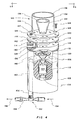
- Fig. 4 shows the inventive modifications to a submersible pump, here the "GRUNDFOS" submersible pump; however, other submersible pumps may be modified in a similar manner.
- the pump is invented to place the impeller 100 on top and the discharge pipe 102 on the bottom.
- the housing 103, motor 104, bearings 106, 108, and hermetic sealing material 110, along with other material structures relating to the water seal, are left untouched.
- the suction screen is removed from the submersible pump housing 103, along with the pump volute plate, and discarded leaving the housing with a suitable seat 112 having bolt holes (not seen in Fig. 4) which are provided by the manufacturer for making an attachment of the suction screen to the housing body 103.
- a collar 116 is manufactured with bolt holes 114 at locations which are in alignment with the bolt holes in the submersible pump seat 112 that were originally designed to secure the suction screen to the submersible pump housing 103.
- a weir 120 is constructed to provide the unbroken curtain of water that coats the inside wall of a funnel 122 which introduces the dry polymer to the eye of impeller 100.
- weir 120 has been drawn as if it is made of a clear and transparent material so that its construction can be seen. In reality, it is preferably constructed of stainless steel, or the like.
- the weir has a base plate 124 with bolt holes 126 aligned with the bolt holes 114 in collar 116 and bolt holes on the seat 112 originally provided for attaching the suction screen onto the inverted submersible pump housing 103. Therefore, the collar 116 and base plate 124 may be attached to the submersible pump by passing bolts 125 through these aligned bolt holes. Suitable gaskets 128, 130 respectively seal the collar 116 to the submersible pump seat 112 and the base plate 124 to the collar 116.
- top edge 134 of funnel 122 is lower than the top edge 136 of sleeve 132.
- An L-shaped passageway is formed in collar 116, leading from a threaded entrance opening 140 to an exit port 142 which is inside the perimeter of the sleeve 132.
- a suitably placed hole 144 in the gasket 130 seals the output port 142 of the L-shaped passage way 136 to the entrance port 146 inside sleeve 132. Therefore, if water is introduced through threaded opening 140, the water will rise inside sleeve 132 until it reaches the level of the upper funnel edge 134. If the edge is level with respect to gravity, water will spill over edge 134, uniformly surround the periphery and uniformly cover the interior funnel wall. There is no need for special equipment for swirling the water in the funnel bowl. By adjusting the amount of flow of water through opening 140, it is possible to precisely control the weir action.
- a level 147 (Fig. 4A) is affixed to the base plate 124.
- This level is a conventional cylindrical chamber 125 which contains liquid with a bubble B and which has a circular target T imprinted on a transparent top window W.
- the bubble B is centered in the target T the upper edge 136 of the funnel is level with respect to gravity.
- the rate of the inflow of water through hole 146 is adjusted so that the impeller does not become hydraulically locked. That is, the eye 149 (Fig. 5) of the impeller is open to air and is not filled with water. Also, since there is an almost fail safe guarantee of uniform wetting of the inside funnel wall a minimum amount of water is required as compared to the amount of water required by my patented system. This minimization of water consumption both reduces cost and simplifies the procedures by doing away with the need for eliminating the excess water.
- the dry polymer is dropped into the eye 149 (Fig. 5) of the impeller 100 where it is uniformly mixed with the water.
- the mixture is discharged through a port 148 in the impeller chamber and down a discharge pipe 150 to the discharge port 102 at the bottom of the inverted submersible pump.
- An eductor 152 is connected to the discharge port 102.
- the eductor is basically a venturi wherein an inflowing stream 154 of water creates a low venturi pressure that helps pull the processed polymer from the impeller chamber and down pipe 150.
- the mixture of inflowing water 154 and the processed polymer in pipe 150 is discharged from eductor port 158.
- the processed polymer is further processed by any suitable method.
- One suitable method might be somewhat as shown in Fig. 6 of my patent 5,407,975.
- One primary difference between the invention and the system of this Fig. 6 is the manner in which the patent eductor 134 is used and the use of an air sparger 136.
- the eductor 134 is connected with the low pressure port drawing off surplus water at the top 44 of the bowl 34.
- the low pressure eductor port is connected to draw the processed polymer from pipe 150.
- an air sparger is used to enhance the aging of the high solids processed polymer. In the present invention, there is no need to use an air sparger because the small amounts of polymer do not require special efforts to enhance aging.
- the entire submersible pump housing 103 (Figs. 4 and 5) is preferably enclosed within an outer sleeve or housing 160 (Fig. 6) which protects it from mechanical damage, from contaminants, and presents an attractive appearance.
- the sleeve or housing 160 preferably includes an inside shelf 162 having a central hole through which the submersible pump housing 103 slips.
- a support plate 163 having an outside diameter larger than the inside diameter of the hole in the inside shelf 162 is fitted under the collar 116 of the submersible pump.
- a suitable number of screws (such as 164, 166) extend through holes in support plate 163 and rest upon shelf 162. These screws may be turned to bring the bubble B (Fig. 4A) in level 147 under the target T etched on a window W in the level. When this adjustment is completed, the weir effect produces the desired unbroken curtain of water lining the interior of the funnel.
Landscapes
- Chemical & Material Sciences (AREA)
- Chemical Kinetics & Catalysis (AREA)
- Engineering & Computer Science (AREA)
- Mechanical Engineering (AREA)
- Dispersion Chemistry (AREA)
- Structures Of Non-Positive Displacement Pumps (AREA)
Applications Claiming Priority (2)
| Application Number | Priority Date | Filing Date | Title |
|---|---|---|---|
| US08/522,842 US5599101A (en) | 1995-09-01 | 1995-09-01 | Dry polymer processing system |
| US522842 | 1995-09-01 |
Publications (3)
| Publication Number | Publication Date |
|---|---|
| EP0760381A2 true EP0760381A2 (fr) | 1997-03-05 |
| EP0760381A3 EP0760381A3 (fr) | 1997-09-10 |
| EP0760381B1 EP0760381B1 (fr) | 2003-06-25 |
Family
ID=24082609
Family Applications (1)
| Application Number | Title | Priority Date | Filing Date |
|---|---|---|---|
| EP96302825A Expired - Lifetime EP0760381B1 (fr) | 1995-09-01 | 1996-04-23 | Système de traitement des polymères secs |
Country Status (4)
| Country | Link |
|---|---|
| US (2) | US5599101A (fr) |
| EP (1) | EP0760381B1 (fr) |
| CA (1) | CA2174703C (fr) |
| DE (1) | DE69628790T2 (fr) |
Families Citing this family (15)
| Publication number | Priority date | Publication date | Assignee | Title |
|---|---|---|---|---|
| US5599101A (en) * | 1995-09-01 | 1997-02-04 | Pardikes; Dennis G. | Dry polymer processing system |
| US6007236A (en) | 1995-12-11 | 1999-12-28 | Maguire; Stephen B. | Weigh scale blender and method |
| DE69732659T2 (de) * | 1996-12-13 | 2005-12-29 | Maguire Products, Inc. | Gravimetrischer mischer von reduzierten abmessungen mit abnehmbarer zuführvorrichtung |
| US6467943B1 (en) * | 1997-05-02 | 2002-10-22 | Stephen B. Maguire | Reduced size gravimetric blender |
| US6280079B1 (en) * | 1998-12-24 | 2001-08-28 | United Microelectronics Corp. | Method of mixing slurries |
| US6384109B1 (en) | 1999-03-25 | 2002-05-07 | Proflow, Inc. | Polymer make-down unit with flushing feature |
| US6642351B1 (en) | 2000-06-26 | 2003-11-04 | Cytec Technology Corp. | Dispersal of polyacrylamides |
| US20100204441A1 (en) * | 2001-06-14 | 2010-08-12 | Pardikes Dennis G | Means for and methods of processing superfine dry polymer |
| US10201915B2 (en) | 2006-06-17 | 2019-02-12 | Stephen B. Maguire | Gravimetric blender with power hopper cover |
| US8092070B2 (en) * | 2006-06-17 | 2012-01-10 | Maguire Stephen B | Gravimetric blender with power hopper cover |
| US20090268547A1 (en) * | 2008-04-14 | 2009-10-29 | Norchem Industries | Devices, systems and methods for dry powder processing |
| US10138075B2 (en) | 2016-10-06 | 2018-11-27 | Stephen B. Maguire | Tower configuration gravimetric blender |
| USD817555S1 (en) * | 2015-12-09 | 2018-05-08 | Oerlikon Metco (Us) Inc. | Hopper |
| US10213753B2 (en) | 2017-03-16 | 2019-02-26 | UGSI Chemical Feed, Inc. | High-capacity polymer system and method of preparing polymeric mixtures |
| US12516457B2 (en) | 2020-05-29 | 2026-01-06 | Kimberly-Clark Worldwide, Inc. | Apparatus for forming a substrate |
Family Cites Families (15)
| Publication number | Priority date | Publication date | Assignee | Title |
|---|---|---|---|---|
| GB1276030A (en) * | 1969-12-23 | 1972-06-01 | Coal Industry Patents Ltd | Method of and apparatus for dispersing particulate materials in a liquid |
| US3804303A (en) * | 1971-03-05 | 1974-04-16 | A Fassauer | System for metering particulate material |
| US3840213A (en) * | 1972-04-03 | 1974-10-08 | Gen Signal Corp | Particle wetting apparatus |
| US4175873A (en) * | 1976-09-10 | 1979-11-27 | Funken Co., Ltd. | Process and apparatus for mechanically mixing two immiscible liquids and one or more other substances |
| US4184771A (en) * | 1978-08-24 | 1980-01-22 | Geosource Inc. | Centrifugal mud mixer |
| DE3243671A1 (de) * | 1982-11-25 | 1984-05-30 | Karg Ytron Gmbh | Vorrichtung zum kontinuierlichen mischen pulvriger stoffe mit fluessigkeiten |
| US4603156A (en) * | 1984-03-12 | 1986-07-29 | Diatec Polymers | Method of dispersing dry, water-soluble polymers in water |
| US4529794A (en) * | 1984-03-29 | 1985-07-16 | Diatec Polymers | Method of rapidly dissolving polymers in water |
| DE3441529A1 (de) * | 1984-11-14 | 1986-05-22 | Alfred Kärcher GmbH & Co, 7057 Winnenden | Vorrichtung zum erzeugen einer stabilen emulsion zur verwendung in reinigungs- und entgiftungsgeraeten |
| US4778280A (en) * | 1986-06-25 | 1988-10-18 | Stranco, Inc. | Mixing apparatus |
| US5252635A (en) * | 1987-08-25 | 1993-10-12 | Stranco, Inc. | Polymer activation method using two separate mixing zones |
| DE4132066A1 (de) * | 1990-09-27 | 1992-04-02 | Dennis G Pardikes | Mischvorrichtung fuer trockene polymere und elektrolyte |
| US5338779A (en) * | 1992-09-18 | 1994-08-16 | Stranco, Inc | Dry polymer activation apparatus and method |
| US5344233A (en) * | 1993-05-11 | 1994-09-06 | J. R. Simplot Co. | Apparatus for dispensing hydratable material |
| US5599101A (en) * | 1995-09-01 | 1997-02-04 | Pardikes; Dennis G. | Dry polymer processing system |
-
1995
- 1995-09-01 US US08/522,842 patent/US5599101A/en not_active Expired - Lifetime
-
1996
- 1996-04-22 CA CA002174703A patent/CA2174703C/fr not_active Expired - Fee Related
- 1996-04-23 DE DE69628790T patent/DE69628790T2/de not_active Expired - Lifetime
- 1996-04-23 EP EP96302825A patent/EP0760381B1/fr not_active Expired - Lifetime
- 1996-07-01 US US08/673,495 patent/US5879080A/en not_active Expired - Lifetime
Also Published As
| Publication number | Publication date |
|---|---|
| CA2174703A1 (fr) | 1997-03-02 |
| EP0760381B1 (fr) | 2003-06-25 |
| DE69628790D1 (de) | 2003-07-31 |
| DE69628790T2 (de) | 2004-04-08 |
| CA2174703C (fr) | 2009-03-31 |
| US5599101A (en) | 1997-02-04 |
| US5879080A (en) | 1999-03-09 |
| EP0760381A3 (fr) | 1997-09-10 |
Similar Documents
| Publication | Publication Date | Title |
|---|---|---|
| CA2174703C (fr) | Systeme de traitement de polymere sec | |
| US4934914A (en) | Portable motor pump | |
| US5980100A (en) | Apparatus for treating liquids | |
| US4154678A (en) | Skimmer device | |
| EP0626877B1 (fr) | Appareil de decantation | |
| KR100855729B1 (ko) | 수중교반 펌프 | |
| CA2184454C (fr) | Dispositif de traitement de polymeres secs | |
| AU4156700A (en) | A separation device | |
| US5238363A (en) | Dual suction vertical pump with pendant auger | |
| KR100301292B1 (ko) | 오.폐수의 처리방법 및 그 장치 | |
| US5322357A (en) | Apparatus for blending a powder with a liquid | |
| US5851066A (en) | Floating mixer | |
| US6200202B1 (en) | System and method for supplying slurry to a semiconductor processing machine | |
| ATE95083T1 (de) | Fahrbare vorrichtung zur sammlung und verarbeitung von kunststoffbehaeltern und/oder heterogenem kunststoffmaterial. | |
| US2269583A (en) | Material separation device | |
| JPS6369514A (ja) | 揚砂装置の制御方法 | |
| US20200086329A1 (en) | Flotation Separation Device | |
| CA2443684A1 (fr) | Dispositif pour brasser et aerer un liquide dans une cuve de traitement | |
| CN213435062U (zh) | 一种矿物浮选装置 | |
| CN209573146U (zh) | 清洗池水位自动控制装置及其废水回收装置 | |
| CN208727388U (zh) | 一种带混料功能的化工用卫生泵 | |
| EP0740575B1 (fr) | Appareil de purification d'air | |
| JPH05321870A (ja) | フローティングポンプ | |
| JPS638419Y2 (fr) | ||
| CN108905856A (zh) | 一种带混料功能的化工用卫生泵 |
Legal Events
| Date | Code | Title | Description |
|---|---|---|---|
| PUAI | Public reference made under article 153(3) epc to a published international application that has entered the european phase |
Free format text: ORIGINAL CODE: 0009012 |
|
| AK | Designated contracting states |
Kind code of ref document: A2 Designated state(s): DE FR GB IT |
|
| PUAL | Search report despatched |
Free format text: ORIGINAL CODE: 0009013 |
|
| AK | Designated contracting states |
Kind code of ref document: A3 Designated state(s): DE FR GB IT |
|
| 17P | Request for examination filed |
Effective date: 19980307 |
|
| 17Q | First examination report despatched |
Effective date: 20020426 |
|
| GRAH | Despatch of communication of intention to grant a patent |
Free format text: ORIGINAL CODE: EPIDOS IGRA |
|
| GRAH | Despatch of communication of intention to grant a patent |
Free format text: ORIGINAL CODE: EPIDOS IGRA |
|
| GRAA | (expected) grant |
Free format text: ORIGINAL CODE: 0009210 |
|
| AK | Designated contracting states |
Designated state(s): DE FR GB IT |
|
| PG25 | Lapsed in a contracting state [announced via postgrant information from national office to epo] |
Ref country code: IT Free format text: LAPSE BECAUSE OF FAILURE TO SUBMIT A TRANSLATION OF THE DESCRIPTION OR TO PAY THE FEE WITHIN THE PRESCRIBED TIME-LIMIT;WARNING: LAPSES OF ITALIAN PATENTS WITH EFFECTIVE DATE BEFORE 2007 MAY HAVE OCCURRED AT ANY TIME BEFORE 2007. THE CORRECT EFFECTIVE DATE MAY BE DIFFERENT FROM THE ONE RECORDED. Effective date: 20030625 Ref country code: FR Free format text: LAPSE BECAUSE OF FAILURE TO SUBMIT A TRANSLATION OF THE DESCRIPTION OR TO PAY THE FEE WITHIN THE PRESCRIBED TIME-LIMIT Effective date: 20030625 |
|
| REG | Reference to a national code |
Ref country code: GB Ref legal event code: FG4D |
|
| REF | Corresponds to: |
Ref document number: 69628790 Country of ref document: DE Date of ref document: 20030731 Kind code of ref document: P |
|
| PLBE | No opposition filed within time limit |
Free format text: ORIGINAL CODE: 0009261 |
|
| STAA | Information on the status of an ep patent application or granted ep patent |
Free format text: STATUS: NO OPPOSITION FILED WITHIN TIME LIMIT |
|
| 26N | No opposition filed |
Effective date: 20040326 |
|
| EN | Fr: translation not filed | ||
| PGFP | Annual fee paid to national office [announced via postgrant information from national office to epo] |
Ref country code: GB Payment date: 20120613 Year of fee payment: 17 |
|
| PGFP | Annual fee paid to national office [announced via postgrant information from national office to epo] |
Ref country code: DE Payment date: 20120711 Year of fee payment: 17 |
|
| GBPC | Gb: european patent ceased through non-payment of renewal fee |
Effective date: 20130423 |
|
| PG25 | Lapsed in a contracting state [announced via postgrant information from national office to epo] |
Ref country code: GB Free format text: LAPSE BECAUSE OF NON-PAYMENT OF DUE FEES Effective date: 20130423 Ref country code: DE Free format text: LAPSE BECAUSE OF NON-PAYMENT OF DUE FEES Effective date: 20131101 |
|
| REG | Reference to a national code |
Ref country code: DE Ref legal event code: R119 Ref document number: 69628790 Country of ref document: DE Effective date: 20131101 |