EP0760421B1 - Poussoir de soupape - Google Patents
Poussoir de soupape Download PDFInfo
- Publication number
- EP0760421B1 EP0760421B1 EP96201995A EP96201995A EP0760421B1 EP 0760421 B1 EP0760421 B1 EP 0760421B1 EP 96201995 A EP96201995 A EP 96201995A EP 96201995 A EP96201995 A EP 96201995A EP 0760421 B1 EP0760421 B1 EP 0760421B1
- Authority
- EP
- European Patent Office
- Prior art keywords
- skirt
- roller
- valve
- valve lifter
- lifter
- Prior art date
- Legal status (The legal status is an assumption and is not a legal conclusion. Google has not performed a legal analysis and makes no representation as to the accuracy of the status listed.)
- Expired - Lifetime
Links
- 230000000712 assembly Effects 0.000 description 3
- 238000000429 assembly Methods 0.000 description 3
- 230000009977 dual effect Effects 0.000 description 3
- 239000000919 ceramic Substances 0.000 description 2
- 238000010276 construction Methods 0.000 description 2
- 229910000831 Steel Inorganic materials 0.000 description 1
- 230000003213 activating effect Effects 0.000 description 1
- 230000003466 anti-cipated effect Effects 0.000 description 1
- 238000005452 bending Methods 0.000 description 1
- 238000002485 combustion reaction Methods 0.000 description 1
- 238000004891 communication Methods 0.000 description 1
- 238000000034 method Methods 0.000 description 1
- 239000010959 steel Substances 0.000 description 1
Images

Classifications
-
- F—MECHANICAL ENGINEERING; LIGHTING; HEATING; WEAPONS; BLASTING
- F01—MACHINES OR ENGINES IN GENERAL; ENGINE PLANTS IN GENERAL; STEAM ENGINES
- F01L—CYCLICALLY OPERATING VALVES FOR MACHINES OR ENGINES
- F01L1/00—Valve-gear or valve arrangements, e.g. lift-valve gear
- F01L1/20—Adjusting or compensating clearance
- F01L1/22—Adjusting or compensating clearance automatically, e.g. mechanically
- F01L1/24—Adjusting or compensating clearance automatically, e.g. mechanically by fluid means, e.g. hydraulically
- F01L1/245—Hydraulic tappets
- F01L1/25—Hydraulic tappets between cam and valve stem
-
- F—MECHANICAL ENGINEERING; LIGHTING; HEATING; WEAPONS; BLASTING
- F01—MACHINES OR ENGINES IN GENERAL; ENGINE PLANTS IN GENERAL; STEAM ENGINES
- F01L—CYCLICALLY OPERATING VALVES FOR MACHINES OR ENGINES
- F01L1/00—Valve-gear or valve arrangements, e.g. lift-valve gear
- F01L1/12—Transmitting gear between valve drive and valve
- F01L1/14—Tappets; Push rods
- F01L1/143—Tappets; Push rods for use with overhead camshafts
-
- F—MECHANICAL ENGINEERING; LIGHTING; HEATING; WEAPONS; BLASTING
- F01—MACHINES OR ENGINES IN GENERAL; ENGINE PLANTS IN GENERAL; STEAM ENGINES
- F01L—CYCLICALLY OPERATING VALVES FOR MACHINES OR ENGINES
- F01L2305/00—Valve arrangements comprising rollers
- F01L2305/02—Mounting of rollers
-
- F—MECHANICAL ENGINEERING; LIGHTING; HEATING; WEAPONS; BLASTING
- F01—MACHINES OR ENGINES IN GENERAL; ENGINE PLANTS IN GENERAL; STEAM ENGINES
- F01L—CYCLICALLY OPERATING VALVES FOR MACHINES OR ENGINES
- F01L2307/00—Preventing the rotation of tappets
-
- Y—GENERAL TAGGING OF NEW TECHNOLOGICAL DEVELOPMENTS; GENERAL TAGGING OF CROSS-SECTIONAL TECHNOLOGIES SPANNING OVER SEVERAL SECTIONS OF THE IPC; TECHNICAL SUBJECTS COVERED BY FORMER USPC CROSS-REFERENCE ART COLLECTIONS [XRACs] AND DIGESTS
- Y10—TECHNICAL SUBJECTS COVERED BY FORMER USPC
- Y10T—TECHNICAL SUBJECTS COVERED BY FORMER US CLASSIFICATION
- Y10T74/00—Machine element or mechanism
- Y10T74/21—Elements
- Y10T74/2101—Cams
- Y10T74/2107—Follower
Definitions
- the invention relates to valve lifters for an internal combustion engine.
- U.S.Patent No. 5,361,733 discloses a roller valve direct acting hydraulic lifter having a design which minimizes lifter body length through the utilization of two, essentially side mounted roller and shaft assemblies which are placed adjacent to the hydraulic element as shown in Figure 8 of the reference. This design limits minimum lifter diameter for support of each roller shaft end.
- both ends of each roller shaft are received in openings in coaxial inner and outer walls of the lifter body. The walls supporting the shaft add to the diameter of the lifter as they require a substantial radial thickness to support the force imparted on the shaft through the roller and to facilitate fixing of the shaft through the use of a pin or other known means for restraint.
- a roller hydraulic valve lifter in a preferred embodiment of the invention, includes a follower body carrying diametrically mounted shaft and roller assemblies.
- the body may include an outer cylindrical skirt and an inner, cylindrical skirt extending coaxial with the outer skirt and defining an annular space therebetween.
- the outer skirt includes an opening supporting one end of a roller shaft therein.
- the shaft extends radially inwardly towards the inner cylindrical skirt such that the inner end of the shaft is placed in abutment with a portion of the inner skirt.
- a roller is supported by the shaft, within the annular recess between the outer and the inner skirts.
- the cantilever shaft is effective to support the roller thereon.
- Such cantilever shaft and roller assemblies are applicable to single and double roller lifter applications.
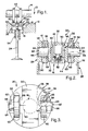
- an engine 10 includes a head and/or carrier component 12 supporting a camshaft 14 and having a sleeve or bore 16 in communication with an oil pressure gallery 18 to thereby receive a plurality of roller direct acting hydraulic valve lifters 20, only one being shown.
- the camshaft includes cams 22, for each of the inlet and exhaust valves 24 of the engine 10.
- the cams 22 are configured to actuate the valves 24 over at least a portion of the lift curve of each valve.
- the roller lifter 20 includes an annular follower body 26 having a cylindrical outer skirt 28, depending from an upper portion or head 30, that is reciprocable in bore 16 in the engine cam carrier 12.
- the upper head 30 also includes an inner cylindrical surface or skirt 32 spaced concentrically within the outer skirt 28.
- the inner skirt 32 includes an outer surface 36 which faces the inner surface 38 of the outer skirt 28, and an inner surface 40 which defines a hollow cylinder 41 having a closed end 42 and an open end 44.
- HEA hydraulic lash adjuster or hydraulic element assembly
- This HEA may include a hollow piston 48 internally carrying a plunger 50 with a check valve 52 and other elements similar to conventional HEA's.
- the piston 48 of HEA 46 may directly engage the stem of the valve 24 for actuating it in an open direction.
- a valve spring 54 acting against the valve 24 and a fixed seat, not shown, in the engine 10 biases the valve 24 in a closing direction while similarly biasing the roller lifter 20 against the cams 22.
- rollers 60 are located between the inner and outer surfaces 38,36 of outer and inner skirts 28,32.
- the rollers engage the cams 22 and are rotatably carried by suitable bearings 61, supported on roller shafts 62 extending transversely across the recesses 58.
- the rollers 60 are effective to reduce the friction of the valve mechanism during operation on the cams 22.
- Transverse openings 64 in the outer skirt 28 receive the outer ends 66 of the roller shafts 62 while the inner ends 68 of the shafts 62 are placed in abutment against flattened portion 55 of the outer surface 36 of the inner cylindrical skirt 32.
- the outer ends 66 of the shafts 62 are fixed in position within the openings 64 using an interference fit between the shaft and the opening or through the use of another suitable method such as staking or pinning.
- the inner end 68 of each shaft 62 is in frictional contact with the skirt surface 36 and operates to resist bending forces acting on the cantilevered shaft 62 caused by the action of the cams 22 on the rollers 60.
- a ceramic shaft may be desirable to avoid unwanted deflection due to ceramic's lower deflection rate over a similar steel shaft.
- the cam 22 actuates the rollers 60 to move the valve lifter 20 and the valve 24 according to a preset lift curve.
- the arrangement provides a compact construction for a direct activating valve lifter having dual friction reducing rollers with the HEA located between the rollers.
- Application of the cantilever roller shaft of the present invention supports minimization of the valve lifter diameter by allowing a reduction in the required minimum thickness of the inner skirt 32, thereby eliminating the need to support the radially inner end of the roller shaft within an opening in the inner skirt.
- the manner of supporting the roller shaft, as described above, is applicable in cases in which the inner cylinder 41 is not readily accessible during the construction of the lifter, making location and fixing of the inner shaft end in an opening in the inner cylinder difficult.
Landscapes
- Engineering & Computer Science (AREA)
- Mechanical Engineering (AREA)
- General Engineering & Computer Science (AREA)
- Valve-Gear Or Valve Arrangements (AREA)
Claims (4)
- Poussoir de soupape comportant un suiveur de came (20) comportant un corps formant suiveur (26) configuré pour recevoir un rouleau venant au contact d'une came (60), ledit rouleau étant disposé pour tourner sur un arbre transversal (62) supporté radialement à une première extrémité (66) dans une ouverture (64) située dans ledit corps formant suiveur, et au niveau d'une seconde extrémité (68) par un contact avec frottement avec une surface (35) dudit corps formant suiveur.
- Poussoir de soupape selon la revendication 1, dans lequel ledit corps formant suiveur est configuré pour recevoir deux rouleaux venant au contact d'une came (60), disposés pour tourner sur des arbres transversaux (62).
- Poussoir de soupape selon la revendication 2, dans lequel ledit corps formant suiveur comporte une jupe extérieure cylindrique (28) et une jupe intérieure cylindrique (32) définissant des évidements espacés latéralement (58) entre celles-ci, pour recevoir lesdits rouleaux venant au contact d'une came dans ceux-ci, ladite jupe intérieure cylindrique (32) ayant une surface extérieure (36) et une surface intérieure (40), et lesdits rouleaux sont supportés sur lesdits arbres transversaux s'étendant dans lesdits évidements, lesdits arbres étant supportés au niveau desdites premières extrémités radialement extérieures dans les ouvertures (64) de ladite jupe extérieure cylindrique (28), et au niveau des extrémités radiales intérieures par un contact avec frottement avec ladite surface extérieure (36) de ladite jupe intérieure cylindrique (32).
- Poussoir de soupape selon la revendication 3, dans lequel ladite surface intérieure (40) de ladite jupe intérieure cylindrique (32) définit un cylindre creux (41) ayant une première extrémité fermée (42) et une seconde extrémité ouverte (44) configurée pour recevoir un dispositif d'ajustement hydraulique de jeu (46) destiné à venir en contact avec la soupape d'un moteur.
Applications Claiming Priority (2)
| Application Number | Priority Date | Filing Date | Title |
|---|---|---|---|
| US51748395A | 1995-08-21 | 1995-08-21 | |
| US517483 | 1995-08-21 |
Publications (2)
| Publication Number | Publication Date |
|---|---|
| EP0760421A1 EP0760421A1 (fr) | 1997-03-05 |
| EP0760421B1 true EP0760421B1 (fr) | 2001-04-04 |
Family
ID=24060001
Family Applications (1)
| Application Number | Title | Priority Date | Filing Date |
|---|---|---|---|
| EP96201995A Expired - Lifetime EP0760421B1 (fr) | 1995-08-21 | 1996-07-15 | Poussoir de soupape |
Country Status (3)
| Country | Link |
|---|---|
| US (1) | US5775275A (fr) |
| EP (1) | EP0760421B1 (fr) |
| DE (1) | DE69612339T2 (fr) |
Families Citing this family (11)
| Publication number | Priority date | Publication date | Assignee | Title |
|---|---|---|---|---|
| US5960758A (en) * | 1998-05-05 | 1999-10-05 | General Motors Corporation | Roller cam follower bearing shaft retention |
| US6289765B1 (en) * | 1999-09-20 | 2001-09-18 | Delphi Technologies, Inc. | Roller follower shaft retention |
| US7128034B2 (en) | 2002-10-18 | 2006-10-31 | Maclean-Fogg Company | Valve lifter body |
| US7028654B2 (en) | 2002-10-18 | 2006-04-18 | The Maclean-Fogg Company | Metering socket |
| US6871622B2 (en) | 2002-10-18 | 2005-03-29 | Maclean-Fogg Company | Leakdown plunger |
| US7273026B2 (en) | 2002-10-18 | 2007-09-25 | Maclean-Fogg Company | Roller follower body |
| US7191745B2 (en) | 2002-10-18 | 2007-03-20 | Maclean-Fogg Company | Valve operating assembly |
| WO2006094213A1 (fr) * | 2005-03-03 | 2006-09-08 | Timken Us Corporation | Ensemble poussoir |
| DE102006045933A1 (de) * | 2006-09-28 | 2008-04-03 | Robert Bosch Gmbh | Stößelbaugruppe für eine Hochdruckpumpe und Hochdruckpumpe mit wenigstens einer Stößelbaugruppe |
| FR2998614A1 (fr) * | 2012-11-29 | 2014-05-30 | Skf Ab | Suiveur de came avec dispositif anti-rotation |
| JP5956920B2 (ja) * | 2012-12-14 | 2016-07-27 | 株式会社コガネイ | 液体供給装置 |
Family Cites Families (5)
| Publication number | Priority date | Publication date | Assignee | Title |
|---|---|---|---|---|
| AT305698B (de) * | 1971-04-02 | 1973-03-12 | Friedmann & Maier Ag | Rollenstößel |
| US4335685A (en) * | 1979-10-19 | 1982-06-22 | Caterpillar Tractor Co. | Lifter assembly |
| US5178107A (en) * | 1991-11-21 | 1993-01-12 | Morel Jr Edward J | Valve lifter |
| US5361733A (en) * | 1993-01-28 | 1994-11-08 | General Motors Corporation | Compact valve lifters |
| US5385124A (en) * | 1994-05-31 | 1995-01-31 | Eaton Corporation | Roller follower axle |
-
1996
- 1996-05-13 US US08/645,339 patent/US5775275A/en not_active Expired - Fee Related
- 1996-07-15 EP EP96201995A patent/EP0760421B1/fr not_active Expired - Lifetime
- 1996-07-15 DE DE69612339T patent/DE69612339T2/de not_active Expired - Fee Related
Also Published As
| Publication number | Publication date |
|---|---|
| US5775275A (en) | 1998-07-07 |
| DE69612339T2 (de) | 2001-07-12 |
| DE69612339D1 (de) | 2001-05-10 |
| EP0760421A1 (fr) | 1997-03-05 |
Similar Documents
| Publication | Publication Date | Title |
|---|---|---|
| CA1329524C (fr) | Culbuteur du type a galet suiveur | |
| US7673601B2 (en) | Valve lifter assembly for selectively deactivating a cylinder | |
| US5361733A (en) | Compact valve lifters | |
| US5655487A (en) | Switchable support element | |
| EP0857860B1 (fr) | Poussoir télescopique pour came étroite | |
| US5090364A (en) | Two-step valve operating mechanism | |
| KR960007963B1 (ko) | 내연기관용 밸브제어수단 | |
| US7207303B2 (en) | Switching element | |
| US5307769A (en) | Low mass roller valve lifter assembly | |
| US5520144A (en) | Valve actuation assembly | |
| US6691657B2 (en) | Two-step finger follower rocker arm | |
| US5546899A (en) | Valve train load transfer device for use with hydraulic roller lifters | |
| JP3207223B2 (ja) | ロッカーアーム | |
| US5127374A (en) | Valve lifter | |
| EP0512698A1 (fr) | Dispositif de soupape réglable pour moteur à combustion interne | |
| EP0332359B1 (fr) | Dispositif de commande de soupape pour moteur à combustion interne | |
| US5775275A (en) | Valve lifter | |
| WO1980000094A1 (fr) | Mecanisme de comme ameliore d'une soupape de moteur | |
| US5359970A (en) | Valve drive for an internal combustion engine | |
| US5606939A (en) | Valve actuation assembly | |
| JPH06317111A (ja) | ローラ弁リフタ | |
| JPH0921306A (ja) | 弁制御システム | |
| US5178107A (en) | Valve lifter | |
| EP0826867A1 (fr) | Commande de soupape d'un moteur à combustion interne | |
| US20010009145A1 (en) | Switchable flat or roller tappet |
Legal Events
| Date | Code | Title | Description |
|---|---|---|---|
| PUAI | Public reference made under article 153(3) epc to a published international application that has entered the european phase |
Free format text: ORIGINAL CODE: 0009012 |
|
| AK | Designated contracting states |
Kind code of ref document: A1 Designated state(s): DE FR GB |
|
| 17P | Request for examination filed |
Effective date: 19970905 |
|
| 17Q | First examination report despatched |
Effective date: 19991202 |
|
| GRAG | Despatch of communication of intention to grant |
Free format text: ORIGINAL CODE: EPIDOS AGRA |
|
| GRAG | Despatch of communication of intention to grant |
Free format text: ORIGINAL CODE: EPIDOS AGRA |
|
| GRAH | Despatch of communication of intention to grant a patent |
Free format text: ORIGINAL CODE: EPIDOS IGRA |
|
| RAP1 | Party data changed (applicant data changed or rights of an application transferred) |
Owner name: DELPHI TECHNOLOGIES, INC. |
|
| GRAH | Despatch of communication of intention to grant a patent |
Free format text: ORIGINAL CODE: EPIDOS IGRA |
|
| GRAA | (expected) grant |
Free format text: ORIGINAL CODE: 0009210 |
|
| AK | Designated contracting states |
Kind code of ref document: B1 Designated state(s): DE FR GB |
|
| REF | Corresponds to: |
Ref document number: 69612339 Country of ref document: DE Date of ref document: 20010510 |
|
| ET | Fr: translation filed | ||
| PGFP | Annual fee paid to national office [announced via postgrant information from national office to epo] |
Ref country code: GB Payment date: 20010618 Year of fee payment: 6 |
|
| PGFP | Annual fee paid to national office [announced via postgrant information from national office to epo] |
Ref country code: FR Payment date: 20010719 Year of fee payment: 6 |
|
| PGFP | Annual fee paid to national office [announced via postgrant information from national office to epo] |
Ref country code: DE Payment date: 20010814 Year of fee payment: 6 |
|
| REG | Reference to a national code |
Ref country code: GB Ref legal event code: IF02 |
|
| PLBE | No opposition filed within time limit |
Free format text: ORIGINAL CODE: 0009261 |
|
| STAA | Information on the status of an ep patent application or granted ep patent |
Free format text: STATUS: NO OPPOSITION FILED WITHIN TIME LIMIT |
|
| 26N | No opposition filed | ||
| PG25 | Lapsed in a contracting state [announced via postgrant information from national office to epo] |
Ref country code: GB Free format text: LAPSE BECAUSE OF NON-PAYMENT OF DUE FEES Effective date: 20020715 |
|
| PG25 | Lapsed in a contracting state [announced via postgrant information from national office to epo] |
Ref country code: DE Free format text: LAPSE BECAUSE OF NON-PAYMENT OF DUE FEES Effective date: 20030201 |
|
| GBPC | Gb: european patent ceased through non-payment of renewal fee |
Effective date: 20020715 |
|
| PG25 | Lapsed in a contracting state [announced via postgrant information from national office to epo] |
Ref country code: FR Free format text: LAPSE BECAUSE OF NON-PAYMENT OF DUE FEES Effective date: 20030331 |
|
| REG | Reference to a national code |
Ref country code: FR Ref legal event code: ST |